change wheel VAUXHALL MOKKA 2015.5 Owner's Manual
[x] Cancel search | Manufacturer: VAUXHALL, Model Year: 2015.5, Model line: MOKKA, Model: VAUXHALL MOKKA 2015.5Pages: 229, PDF Size: 6.45 MB
Page 13 of 229

In brief11
1Central locking system ..........21
2 Power windows .....................29
3 Exterior mirrors .....................27
4 Light switch ......................... 104
5 Cruise control ...................... 137
Speed limiter ....................... 138
Forward collision alert .........139
6 Side air vents ...................... 119
7 Turn and lane-change
signals ................................. 109
Headlight flash ....................105
Low beam and high beam ..105
Buttons for Driver
Information Centre (DIC) ....... 90
8 Instruments ........................... 79
9 Steering wheel controls .......72
10 Windscreen wiper,
windscreen washer system ...73
Rear window wiper, rear
window washer system .........75
11 Centre air vents ................... 11912Electronic Stability Control
(ESC) .................................. 135
Hazard warning flashers ....109
Control indicator for airbag deactivation .......................... 84
13 Anti-theft alarm system
status LED ........................... 25
14 Info-Display .......................... 93
15 Instrument panel storage ......54
16 Glovebox .............................. 55
17 Infotainment system
18 Climate control system ........ 114
19 Stop-start system ................123
Fuel selector ......................... 80
20 AUX input, USB input, SD
card slot
21 Selector lever, manual
transmission ....................... 131
Automatic transmission ......128
22 Parking brake ......................133
23 Power outlet .......................... 7824Parking assist ..................... 142
Descent control system ......... 86
25 Ignition switch with
steering wheel lock ............122
26 Horn ..................................... 73
Driver airbag ........................ 44
27 Steering wheel adjustment ..72
28 Bonnet release lever ..........163
29 Instrument panel storage ......54
Fuse box ............................ 177
Page 56 of 229

54StorageStorageStorage compartments................54
Load compartment .......................66
Roof rack system .........................70
Loading information .....................70Storage compartments9Warning
Do not store heavy or sharp
objects in the storage
compartments. Otherwise, the
storage compartment lid could
open and vehicle occupants could be injured by objects being thrown
around in the event of hard
braking, a sudden change in
direction or an accident.
Instrument panel storage
A storage compartment is located
next to the steering wheel.
A further storage compartment is
located on top of the glovebox.
To open, push the button.
The covers of the storage
compartments should be closed while
driving.
Page 83 of 229

Instruments and controls81
left area=engine operating
temperature not
yet reachedcentral area=normal operating
temperatureright area=temperature too
highCaution
If engine coolant temperature is
too high, stop vehicle, switch off
engine. Danger to engine. Check
coolant level.
Service display
The engine oil life system lets you
know when to change the engine oil
and filter. Based on driving
conditions, the interval at which an
engine oil and filter change will be
indicated can vary considerably.
In the Uplevel-Display and Uplevel-
Combi-Display, the remaining oil life
duration is displayed in the Vehicle
Information Menu .
In the Midlevel-Display, the remaining
engine oil life duration is displayed by
control indicator I, therefore the
ignition must be switched on, with the
engine off.
The menu and function can be
selected via the buttons on the turn
signal lever.
To display the remaining engine oil
life duration:Press MENU to select the Vehicle
Information Menu .
Turn the adjuster wheel to select Remaining Oil Life .
The system must be reset every time the engine oil is changed to ensure
proper functionality. Seek the
assistance of a workshop.
Press the SET/CLR button to reset.
Therefore the ignition must be
switched on, with the engine off.
When the system has calculated that
engine oil life has been diminished,
Change Engine Oil Soon or a warning
code appears in the Driver
Page 93 of 229

Instruments and controls91
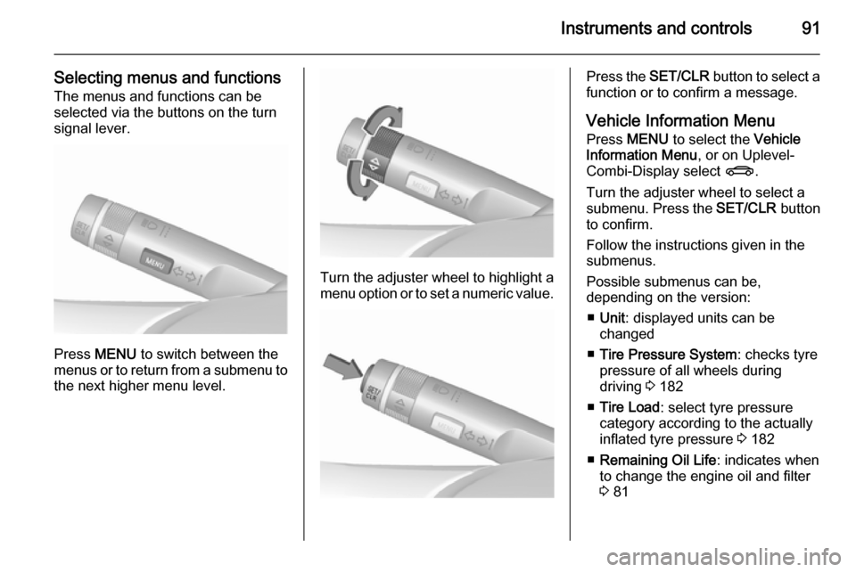
Selecting menus and functionsThe menus and functions can be
selected via the buttons on the turn signal lever.
Press MENU to switch between the
menus or to return from a submenu to the next higher menu level.
Turn the adjuster wheel to highlight a
menu option or to set a numeric value.
Press the SET/CLR button to select a
function or to confirm a message.
Vehicle Information Menu Press MENU to select the Vehicle
Information Menu , or on Uplevel-
Combi-Display select X.
Turn the adjuster wheel to select a
submenu. Press the SET/CLR button
to confirm.
Follow the instructions given in the submenus.
Possible submenus can be,
depending on the version:
■ Unit : displayed units can be
changed
■ Tire Pressure System : checks tyre
pressure of all wheels during
driving 3 182
■ Tire Load : select tyre pressure
category according to the actually
inflated tyre pressure 3 182
■ Remaining Oil Life : indicates when
to change the engine oil and filter
3 81
Page 98 of 229

96Instruments and controls
No.Vehicle message28Right rear turn signal failure53Tighten gas cap54Water in diesel fuel filterS68Service power steeringS73Service all-wheel drive systemS75Service air conditioningS79Top up engine oilS81Service transmissionS82Change engine oil soonS84Engine power is reducedS89Service vehicle soon128Bonnet open134Park assist fault, clean
bumperS136Service parking assist174Low batteryNotice
"S" means "Service vehicle soon".
Seek the assistance of a workshop
immediately.
Vehicle messages on the
Uplevel-Display and Uplevel- Combi-Display
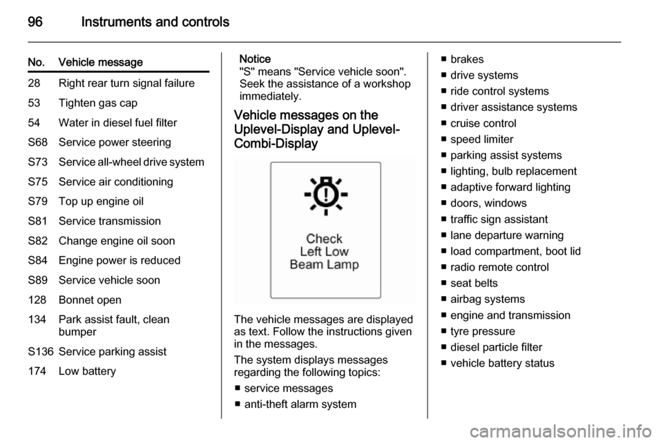
The vehicle messages are displayed
as text. Follow the instructions given
in the messages.
The system displays messages
regarding the following topics:
■ service messages
■ anti-theft alarm system
■ brakes
■ drive systems
■ ride control systems
■ driver assistance systems
■ cruise control
■ speed limiter
■ parking assist systems
■ lighting, bulb replacement
■ adaptive forward lighting
■ doors, windows
■ traffic sign assistant
■ lane departure warning
■ load compartment, boot lid
■ radio remote control
■ seat belts
■ airbag systems
■ engine and transmission
■ tyre pressure
■ diesel particle filter
■ vehicle battery status
Page 111 of 229

Lighting109
If a headlight flash is activated when
the high beam is on, the high beam
assist will be deactivated.
If a headlight flash is activated when
the high beam is off, the high beam
assist will remain activated.
High beam assist is always active
after the ignition is switched on.
Dynamic automatic headlight
levelling
To prevent oncoming traffic from dazzle, headlight levelling is
automatically adjusted based on
inclination information measured by
front and rear axle, acceleration or
deceleration and vehicle speed.
Fault in Adaptive forward
lighting system When the system detects a failure in
the Adaptive forward lighting system,
the system moves to a preset position to avoid dazzling of oncoming traffic.
Have the cause of the failure
remedied by a workshop as soon as
possible.Hazard warning flashers
Operated with the ¨ button.
Turn and lane-change
signalslever up=right turn signallever down=left turn signal
If the lever is moved past the
resistance point, the turn signal is
switched on constantly. When the
steering wheel moves back, the turn
signal is automatically deactivated.
For three flashes, e.g. when changing
lanes, press the lever until resistance
is felt and then release.
Move the lever to the resistance point
and hold for longer indication.
Page 141 of 229

Driving and operating139
Set speed limit
With speed limiter active, hold thumb
wheel turned to RES/+ or briefly turn
to RES/+ repeatedly until the desired
maximum speed is displayed in the
DIC.
Alternatively accelerate to the desired speed and briefly turn thumb wheel to SET/- : the current speed is stored as
maximum speed. Speed limit is
displayed in the DIC.Change speed limit
With speed limiter active, turn thumb
wheel to RES/+ to increase or SET/-
to decrease the desired maximum
speed.
Exceeding the speed limit
In the event of an emergency, it is possible to exceed the speed limit by
depressing the accelerator pedal
firmly beyond the point of resistance.
The limited speed will flash in the DIC and a chime sounds during this
period.
Release the accelerator pedal and the speed limiter function is
reactivated once a speed lower than
the limit speed is obtained.
Deactivation Press y: speed limiter is deactivated
and the vehicle can be driven without
speed limit.
The limited speed is stored and a
corresponding message appears in
the DIC.Resume limit speed
Turn thumb wheel to RES/+. The
stored speed limit will be obtained.
Switching off Press L, the speed limit indication in
the DIC extinguishes. The stored
speed is deleted.
By pressing m to activate cruise
control or adaptive cruise control or
by switching off the ignition, speed
limiter is also deactivated and the
stored speed is deleted.
Forward collision alert
The forward collision alert can help to
avoid or reduce the damage caused
by front-end crashes. If a vehicle
directly ahead is approached too
quickly, a warning chime and alert in
the Driver Information Centre (DIC) is
provided.
Page 163 of 229

Vehicle care161Vehicle careGeneral Information...................161
Vehicle checks ........................... 162
Bulb replacement .......................169
Electrical system ........................175
Vehicle tools .............................. 180
Wheels and tyres .......................181
Jump starting ............................. 194
Towing ....................................... 196
Appearance care .......................198General Information
Accessories and vehicle
modifications
We recommend the use of genuine parts and accessories and factory
approved parts specific for your
vehicle type. We cannot assess or
guarantee reliability of other products
- even if they have a regulatory or
otherwise granted approval.
Do not make any modifications to the electrical system, e.g. changes of
electronic control units (chip tuning).Caution
When transporting the vehicle on
a train or on a recovery vehicle, the
mud flaps might be damaged.
Vehicle storage
Storage for a long period of time
If the vehicle is to be stored for several months:
■ Wash and wax the vehicle.
■ Have the wax in the engine compartment and underbody
checked.
■ Clean and preserve the rubber seals.
■ Fill up fuel tank completely.
■ Change the engine oil.
■ Drain the washer fluid reservoir.
■ Check the coolant antifreeze and corrosion protection.
■ Adjust tyre pressure to the value specified for full load.
■ Park the vehicle in a dry, well ventilated place. Engage first orreverse gear or set selector lever to P . Prevent the vehicle from rolling.
■ Do not apply the parking brake.
Page 192 of 229

190Vehicle care
If tyre pressure is more than
1.3 bar , set it to the correct value.
Repeat the procedure until there
is no more loss of pressure.
If the tyre pressure has fallen
below 1.3 bar, the vehicle must
not be used. Seek the assistance
of a workshop.
18. Stow away tyre repair kit in load compartment.
Notice
The driving characteristics of the
repaired tyre are severely affected,
therefore have this tyre replaced.
If unusual noise is heard or the
compressor becomes hot, turn
compressor off for at least
30 minutes.
The built-in safety valve opens at a
pressure of 102 psi.
Note the expiry date of the kit. After
this date its sealing capability is no
longer guaranteed. Pay attention to
storage information on sealant
bottle.
Replace the used sealant bottle. Dispose of the bottle as prescribed
by applicable laws.
The compressor and sealant can be used from approx. -30 °C.
The adapters supplied can be used
to pump up other items e.g.
footballs, air mattresses, inflatable
dinghies etc. They are located on the
underside of the compressor. To
remove, screw on compressor air
hose and withdraw adapter.
Wheel changing
Some vehicles are equipped with a
tyre repair kit instead of a spare wheel 3 187.Make the following preparations and
observe the following information:
■ Park the vehicle on a level, firm and
non-skid surface. The front wheels
must be in the straight-ahead
position.
■ Apply the parking brake and engage first gear, reverse gear or
P .
■ Remove the spare wheel 3 192.
■ Never change more than one wheel
at once.
■ Use the jack only to change wheels
in case of puncture, not for
seasonal winter or summer tyre
change.
■ The jack is maintenance-free.
■ If the ground on which the vehicle is standing is soft, a solid board
(max. 1 cm thick) should be placed
under the jack.
■ Take heavy objects out of the vehicle before jacking up.
■ No people or animals may be in the
vehicle when it is jacked-up.
Page 193 of 229

Vehicle care191
■ Never crawl under a jacked-upvehicle.
■ Do not start the vehicle when it is raised on the jack.
■ Clean wheel nuts and thread with a
clean cloth before mounting the
wheel.9 Warning
Do not grease wheel bolt, wheel
nut and wheel nut cone.
1. Disengage wheel nut caps with a screwdriver and remove. Pull off
the wheel cover.
2. Fold out the wheel wrench and install ensuring that it locates
securely and loosen each wheel
nut by half a turn.
3. Ensure the jack is correctly positioned under the relevant
vehicle jacking point.
Depending on the equipment, first
remove the covers from the
jacking points.
4. Set the jack to the necessary height. Position it directly below
the jacking point in a manner that prevents it from slipping.
Attach wheel wrench and with the jack correctly aligned rotate wheelwrench until wheel is clear of the
ground.
5. Unscrew the wheel nuts.
6. Change the wheel. Spare wheel 3 192.
7. Screw on the wheel nuts.
8. Lower the vehicle and remove jack.
9. Install the wheel wrench ensuring that it locates securely and tighten
each nut in a crosswise
sequence. Tightening torque is
140 Nm.