sensor VAUXHALL MOKKA 2015 User Guide
[x] Cancel search | Manufacturer: VAUXHALL, Model Year: 2015, Model line: MOKKA, Model: VAUXHALL MOKKA 2015Pages: 223, PDF Size: 6.2 MB
Page 124 of 223

122Driving and operating
Before restarting or to switch off the
engine, turn the key back to position
0 .
During an Autostop, the engine can
be started by depressing the clutch
pedal.
Key lock release
Some vehicles with an automatic
transmission are equipped with an electronic key lock release system.
The key lock release is designed to
prevent ignition key removal unless
the selector lever is in P.
Starting the vehicle at low
temperatures
Starting the engine without additional
heaters is possible down to -25 °С for diesel engines and -30 °C for petrol
engines. Required is an engine oil
with the correct viscosity, the correct fuel, performed services and a
sufficiently charged battery. With
temperatures below -30 °C the
automatic transmission requires a
warming phase of approx. 5 minutes.
The selector lever must be in position P .Automatic Starter Control
This function controls the engine
starting procedure. The driver does
not have to hold the key in position 3.
Once applied, the system will go on starting automatically until the engine
is running. Because of the checking
procedure, the engine starts running
after a short delay.
Possible reasons for a non-starting
engine:
■ Clutch pedal not operated (manual transmission)
■ Brake pedal not operated or selector lever not in P or N
(automatic transmission)
■ Timeout occurred
Turbo engine warm-up Upon start-up, engine available
torque may be limited for a short time, especially when the engine
temperature is cold. The limitation is
to allow the lubrication system to fully
protect the engine.Overrun cut-off
The fuel supply is automatically cut off
during overrun, i.e. when the vehicle
is driven with a gear engaged but accelerator is released.
Stop-start system The stop-start system helps to save
fuel and to reduce the exhaust
emissions. When conditions allow, it
switches off the engine as soon as the
vehicle is at a low speed or at a
standstill, e.g. at a traffic light or in a
traffic jam. It starts the engine
automatically as soon as the clutch is depressed. A battery sensor ensures
that an Autostop is only performed if
the battery is sufficiently charged for
a restart.
Activation The stop-start system is available as
soon as the engine is started, the
vehicle starts-off and the conditions
as stated below in this section are fulfilled.
Page 142 of 223

140Driving and operating
General information
9Warning
Forward collision alert is just a
warning system and does not
apply the brakes. When
approaching a vehicle ahead too
rapidly, it may not provide you
enough time to avoid a collision.
The driver accepts full
responsibility for the appropriate
following distance based on traffic, weather and visibility conditions.
The complete attention of the
driver is always required while
driving. The driver must always be
ready to take action and apply the
brakes.
System limitations
The system is designed to warn only for vehicles, but may react also to
other metallic objects.
In the following cases, forward
collision alert may not detect a vehicle ahead or sensor performance is
limited:
■ on winding roads,
■ when weather limits visibility, e.g. fog, rain, or snow,
■ when the sensor is blocked by snow, ice, slush, mud, dirt, or
windscreen damage.
Parking assist
The parking assist makes parking
easier by measuring the distance between the vehicle and obstacles,
and giving acoustic signals. It is the
driver, however, who bears full
responsibility for the parking
manoeuvre.
The system consists of four ultrasonic parking sensors in the rear bumper. If
the vehicle is equipped with a front
parking assist the system consists of
four additional ultrasonic parking
sensors in the front bumper.
Page 143 of 223

Driving and operating141
Control indicator r 3 86.
Activation
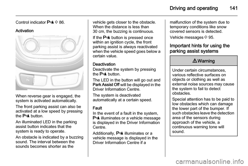
When reverse gear is engaged, the
system is activated automatically.
The front parking assist can also be activated at a low speed by pressing
the r button.
An illuminated LED in the parking assist button indicates that the
system is ready to operate.
An obstacle is indicated by a buzzing
sound. The interval between the sounds becomes shorter as the
vehicle gets closer to the obstacle.
When the distance is less than
30 cm, the buzzing is continuous.
If the r button is pressed once
within an ignition cycle, the front
parking assist is always reactivated
when the vehicle speed goes below a certain value.
Deactivation
Deactivate the system by pressing
the r button.
The LED in the button will go out and
Park Assist Off will be displayed in the
Driver Information Centre.
The system is deactivated
automatically at a certain speed.
Fault
In the event of a fault in the system,
r illuminates or a vehicle message
is displayed in the Driver Information
Centre.
Additionally, r illuminates or a
vehicle message is displayed in the
Driver Information Centre if amalfunction of the system due to
temporary conditions like snow
covered sensors is detected.
Vehicle messages 3 95.
Important hints for using the parking assist systems9 Warning
Under certain circumstances,
various reflective surfaces on
objects or clothing as well as
external noise sources may cause the system to fail to detect
obstacles.
Special attention has to be paid to
low obstacles which can damage
the lower part of the bumper. If
such obstacles leave the detection area of the sensors during
approach of the vehicle, a
continuous warning tone will
sound.
Page 144 of 223

142Driving and operatingCaution
Performance of the sensor can bereduced when sensors are
covered, e.g. by ice or snow.
Performance of the parking assist
systems can be reduced due to
heavy loading.
Special conditions apply if there
are taller vehicles involved (e.g.
off-road vehicles, mini vans,
vans). Object identification in the upper part of these vehicles
cannot be guaranteed.
Objects with a very small reflection
cross section, like objects of
narrow size or soft materials, may
not be detected by the system.
Parking assist will not avoid a
collision with objects which are out
of the detection range of the
sensors.
Notice
The parking assist system
automatically detects factory-fitted
towing equipment. It is deactivated
when the connector is plugged in.
The sensor may detect a non-
existent object (echo disturbance)
caused by external acoustic or
mechanical disturbances.
Notice
The parking assist is deactivated
when the rear carrier system is
extended.
Rear view camera
The rear view camera assists the
driver when reversing by displaying a view of the area behind the vehicle.
The view of the camera is displayed
in the Colour-Info-Display.9 Warning
The rear view camera does not
replace driver vision. Note that
objects that are outside the
camera's field of view and the
advanced parking assist sensors,
e.g. below the bumper or
underneath the vehicle, are not
displayed.
Do not reverse the vehicle by only looking at the Info-Display and
check the surrounding area
behind and around the vehicle
before reversing.
Activation
Rear view camera is automatically
activated when reverse gear is
engaged.
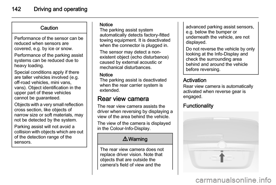
Functionality
Page 145 of 223

Driving and operating143
The camera is mounted in the tailgatehandle and has a viewing angle of
130°.
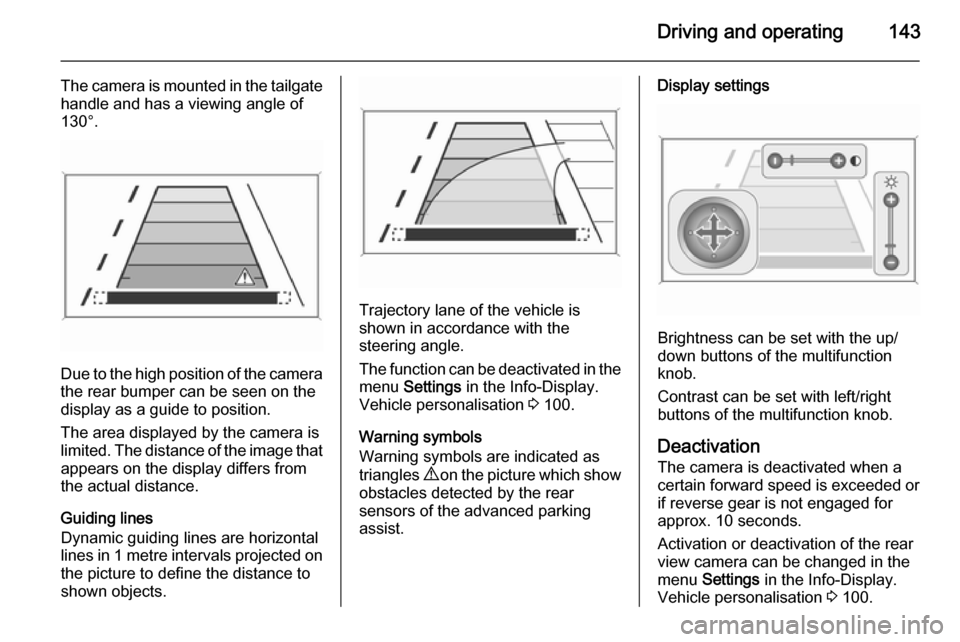
Due to the high position of the camera
the rear bumper can be seen on the
display as a guide to position.
The area displayed by the camera is
limited. The distance of the image that appears on the display differs from
the actual distance.
Guiding lines
Dynamic guiding lines are horizontal
lines in 1 metre intervals projected on
the picture to define the distance to
shown objects.
Trajectory lane of the vehicle is
shown in accordance with the
steering angle.
The function can be deactivated in the
menu Settings in the Info-Display.
Vehicle personalisation 3 100.
Warning symbols
Warning symbols are indicated as
triangles 9 on the picture which show
obstacles detected by the rear
sensors of the advanced parking
assist.
Display settings
Brightness can be set with the up/
down buttons of the multifunction
knob.
Contrast can be set with left/right
buttons of the multifunction knob.
Deactivation
The camera is deactivated when a
certain forward speed is exceeded or if reverse gear is not engaged for
approx. 10 seconds.
Activation or deactivation of the rear
view camera can be changed in the menu Settings in the Info-Display.
Vehicle personalisation 3 100.
Page 173 of 223

Vehicle care171
Fuse extractorA fuse extractor may be located in the fuse box in the engine compartment.
Place the fuse extractor on the
various types of use from the top or
side, and withdraw fuse.
Engine compartment fuse
box
The fuse box is in the engine
compartment.
Disengage the cover, lift it upwards
and remove.
Mini Fuses
No.Circuit1Sunroof2Exterior mirrors3–4–5Electrical brake control module6Intelligent battery sensor7–8Transmission control module9Body control module10Headlight levelling11Rear window wiper12Heated rear window13Headlight actuator (left hand)14Heated exterior mirrors15–16Seat heating17Transmission control module
Page 175 of 223

Vehicle care173
Mini Fuses
No.Circuit1Body control module2Body control module3Body control module4Body control module5Body control module6Body control module7Body control module8Body control module9Door locks10Safety diagnosis module11Door locks12Climate control13Tailgate14Park assist15Lane departure warning, Interior
mirror16Adaptive forward lightingNo.Circuit17Power window driver18Rain sensor19Spare20Steering wheel21Transmission control module22Cigarette lighter23Spare24Spare25Spare26Display27Instrument panel cluster28Adaptive forward lighting29Spare30Spare31Instrument panel cluster32Infotainment, auxiliary, power
outlet
Page 177 of 223

Vehicle care175
No.Circuit1LPG system2Interior mirror, rear view camera3Water in fuel sensor4Spare5Trailer socket6Heated steering wheel7Spare8Trailer control module9Seat, lumbar support, driver10Seat, lumbar support,
passenger11Amplifier12Trailer socket13All-wheel drive14Spare15LPG system16SpareNo.Circuit17Spare18Spare
S/B Fuses
No.Circuit19Power seat driver20Power seat passenger21Trailer control module22Voltage converter23Ignition system24Headlight washer25Spare26Spare27SpareVehicle tools
Tools
Vehicles with tyre repair kit
The tools and tyre repair kit are in the
right side of the load compartment.
3 182.
Page 180 of 223

178Vehicle care
All wheels must be equipped with
pressure sensors and the tyres must
have the prescribed pressure.
Notice
In countries where the tyre pressure monitoring system is legally
required, the use of wheels without
pressure sensors will invalidate the
vehicle type approval.
The current tyre pressures can be
shown in the Vehicle Information
Menu in the Driver Information Centre
(DIC).
The menu can be selected by the
buttons on the turn signal lever.Press the MENU button to select the
Vehicle Information Menu X .
Turn the adjuster wheel to select the
tyre pressure monitoring system.
System status and pressure warnings
are displayed by a message with the
corresponding tyre flashing in the
DIC.
A detected low tyre pressure
condition is indicated by the control
indicator w 3 87.
If w illuminates, stop as soon as
possible and inflate the tyres as
recommended 3 210.
If w flashes for 60-90 seconds and
then illuminates continuously, there is a fault in the system. Consult a
workshop.
After inflating, driving may be
required to update the tyre pressure
values in the DIC. During this time w
may illuminate.
Page 181 of 223

Vehicle care179
If w illuminates at lower temperatures
and extinguishes after some driving,
this could be an indicator for getting
low pressure. Check tyre pressure.
Vehicle messages 3 95.
If the tyre pressure shall be reduced
or increased, switch off ignition.
Only mount wheels with pressure
sensors, otherwise the tyre pressure
will not be displayed and w
illuminates continuously.
A temporary spare wheel is not
equipped with pressure sensors. The
tyre pressure monitoring system is
not operational for these wheels.
Control indicator w illuminates. For
the further three wheels the system
remains operational.
The use of commercially available
liquid tyre repair kits can impair the
function of the system. Factory-
approved repair kits can be used.
External high-power radio equipment
could disrupt the tyre pressure
monitoring system.Each time the tyres are replaced tyre
pressure monitoring system sensors
must be dismounted and serviced. For the screwed sensor: replace
valve core and sealing ring. For
clipped sensor: replace complete
valve stem.
Vehicle loading status
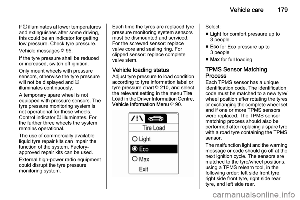
Adjust tyre pressure to load condition according to tyre information label or
tyre pressure chart 3 210, and select
the relevant setting in the menu Tire
Load in the Driver Information Centre,
Vehicle Information Menu 3 90.Select:
■ Light for comfort pressure up to
3 people
■ Eco for Eco pressure up to
3 people
■ Max for full loading
TPMS Sensor Matching
Process
Each TPMS sensor has a unique
identification code. The identification
code must be matched to a new tyre/
wheel position after rotating the tyres
or exchanging the complete wheel set and if one or more TPMS sensors
were replaced. The TPMS sensor matching process should also be
performed after replacing a spare tyre
with a road tyre containing the TPMS
sensor.
The malfunction light and the warning
message or code should go off at the
next ignition cycle. The sensors are
matched to the tyre/wheel positions,
using a TPMS relearn tool, in the
following order: left side front tyre,
right side front tyre, right side rear
tyre, and left side rear.