steering VAUXHALL MOKKA 2015 Owner's Guide
[x] Cancel search | Manufacturer: VAUXHALL, Model Year: 2015, Model line: MOKKA, Model: VAUXHALL MOKKA 2015Pages: 223, PDF Size: 6.2 MB
Page 127 of 223
Driving and operating125uphill slope. Depress foot brake
at the same time to reduce
operating force.
■ Switch off the engine.
■ If the vehicle is on a level surface or uphill slope, engage
first gear or set the selector lever to position P before removing
the ignition key. On an uphill
slope, turn the front wheels
away from the kerb.
If the vehicle is on a downhill
slope, engage reverse gear or
set the selector lever to position
P before removing the ignition
key. Turn the front wheels
towards the kerb.
■ Close the windows and the sunroof.
■ Remove the ignition key. For vehicles with automatic
transmission, the key can only
be removed when the selector
lever is in position P.Turn the steering wheel until the
steering wheel lock is felt to
engage.
■ Lock the vehicle.
■ Activate the anti-theft alarm system.
Notice
In the event of an accident with
airbag deployment, the engine is
turned off automatically if the vehicle
comes to a standstill within a certain
time.
Engine exhaust9 Danger
Engine exhaust gases contain
poisonous carbon monoxide,
which is colourless and odourless and could be fatal if inhaled.
If exhaust gases enter the interior
of the vehicle, open the windows.
Have the cause of the fault
rectified by a workshop.
Avoid driving with an open load
compartment, otherwise exhaust
gases could enter the vehicle.
Diesel particle filter
The diesel particle filter system filters
harmful soot particles out of the
exhaust gases. The system includes
a self-cleaning function that runs
automatically during driving without
any notification. The filter is cleaned
by periodically burning off the soot
particles at high temperature. This
process takes place automatically
under set driving conditions and may
Page 145 of 223
Driving and operating143
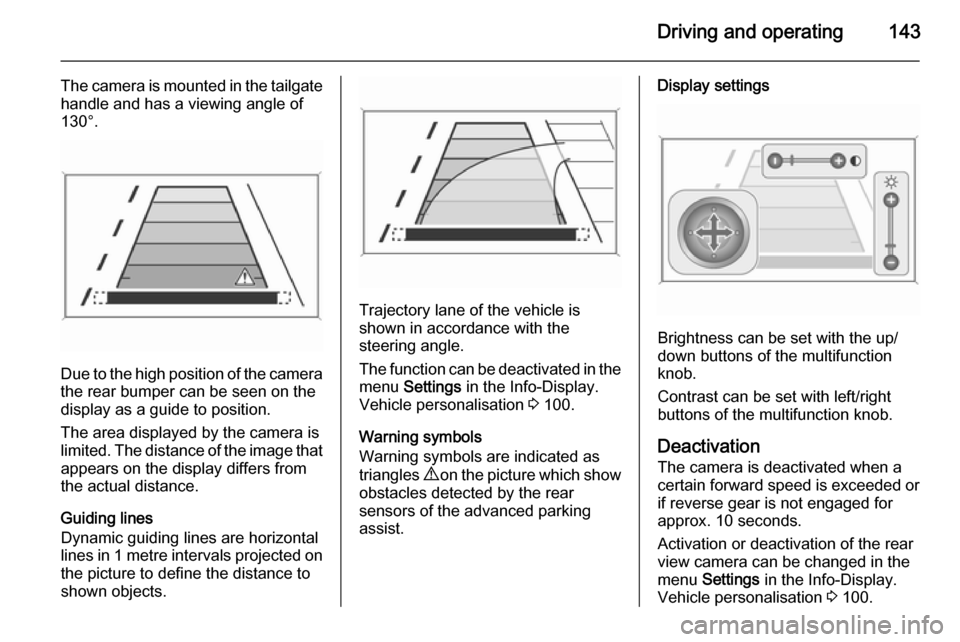
The camera is mounted in the tailgatehandle and has a viewing angle of
130°.
Due to the high position of the camera
the rear bumper can be seen on the
display as a guide to position.
The area displayed by the camera is
limited. The distance of the image that appears on the display differs from
the actual distance.
Guiding lines
Dynamic guiding lines are horizontal
lines in 1 metre intervals projected on
the picture to define the distance to
shown objects.
Trajectory lane of the vehicle is
shown in accordance with the
steering angle.
The function can be deactivated in the
menu Settings in the Info-Display.
Vehicle personalisation 3 100.
Warning symbols
Warning symbols are indicated as
triangles 9 on the picture which show
obstacles detected by the rear
sensors of the advanced parking
assist.
Display settings
Brightness can be set with the up/
down buttons of the multifunction
knob.
Contrast can be set with left/right
buttons of the multifunction knob.
Deactivation
The camera is deactivated when a
certain forward speed is exceeded or if reverse gear is not engaged for
approx. 10 seconds.
Activation or deactivation of the rear
view camera can be changed in the menu Settings in the Info-Display.
Vehicle personalisation 3 100.
Page 149 of 223

Driving and operating147signs. Do not ignore traffic signs
which are not displayed by the
system.
The system does not recognise
any other than the conventional
traffic signs that might give or end
a speed limit.
Do not let this special feature
tempt you into taking risks when
driving.
Always adapt speed to the road
conditions.
The driver assistance systems do not relieve the driver from full
responsibility for vehicle
operation.
Lane departure warning
The lane departure warning systemobserves the lane markings between
which the vehicle is driving via a front camera. The system detects lane
changes and warns the driver in the
event of an unintended lane change
via visual and acoustic signals.
Criteria for the detection of an
unintended lane change are:
■ no operation of turn signals
■ no brake pedal operation
■ no active accelerator operation or speeding-up
■ no active steering
If the driver is active, no warning will
be issued.
Activation
The lane departure warning system is activated by pressing the ) button.
The illuminated LED in the button
indicates that the system is switched
on. When the control indicator ) in
the instrument cluster illuminates
green, the system is ready to operate.
The system is only operable at
vehicle speeds above 35 mph and if
lane markings are available.
When the system recognises an
unintended lane change, the control
indicator ) changes to yellow and
flashes. Simultaneously a chime
sound is activated.
Deactivation
The system is deactivated by
pressing ) button, the LED in the
button extinguishes.
Page 157 of 223

Driving and operating155
1000 kg a speed of 50 mph must not
be exceeded; the use of a stabiliser is recommended.
If the trailer starts snaking, drive more
slowly, do not attempt to correct the
steering and brake sharply if
necessary.
When driving downhill, drive in the
same gear as if driving uphill and
drive at a similar speed.
Adjust tyre pressure to the value
specified for full load 3 210.
Trailer towing Trailer loads The permissible trailer loads are
vehicle and engine-dependent
maximum values which must not be
exceeded. The actual trailer load is
the difference between the actual
gross weight of the trailer and the
actual coupling socket load with the
trailer coupled.
The permissible trailer loads are
specified in the vehicle documents. In
general, they are valid for gradients
up to max. 12 %.The permitted trailer loads apply up to the specified incline and up to an
altitude of 1000 metres above sea
level. Since engine power decreases as altitude increases due to the airbecoming thinner, therefore reducing
climbing ability, the permissible gross train weight also decreases by 10 %
for every 1000 metres of additional
altitude. The gross train weight does
not have to be reduced when driving
on roads with slight inclines (less than
8 %, e.g. motorways).
The permissible gross train weight
must not be exceeded. This weight is
specified on the identification plate
3 200.
Vertical coupling load
The vertical coupling load is the load
exerted by the trailer on the coupling
ball. It can be varied by changing the
weight distribution when loading the
trailer.
The maximum permissible vertical
coupling load (75 kg) is specified on
the towing equipment identification
plate and in the vehicle documents.
Always aim for the maximum load,especially in the case of heavy
trailers. The vertical coupling load
should never fall below 25 kg.
Rear axle load The permissible axle loads (see
identification plate or vehicle
documents) must not be exceeded.
Page 162 of 223
160Vehicle care
temperatures the factory filled coolantprovides frost protection down to
approx. -40 °C.Caution
Only use approved antifreeze.
Coolant level
Caution
Too low a coolant level can cause engine damage.
If the cooling system is cold, the
coolant level should be above the
filling line mark. Top up if the level is
low.9 Warning
Allow the engine to cool before
opening the cap. Carefully open
the cap, relieving the pressure
slowly.
To top up use a 1:1 mixture of
released coolant concentrate mixed
with clean tap water. If no coolant
concentrate is available, use clean
tap water. Install the cap tightly. Have the coolant concentration checked
and have the cause of the coolant
loss remedied by a workshop.
Power steering fluid
Caution
Extremely small amounts of
contamination can cause steering
system damage and cause it to not
work properly. Do not allow
contaminates to contact the fluid
side of the reservoir cap/dipstick or
from entering the reservoir.
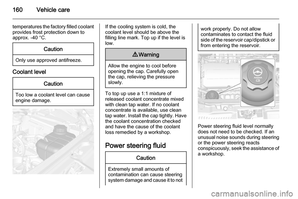
Power steering fluid level normally
does not need to be checked. If an
unusual noise sounds during steering or the power steering reacts
conspicuously, seek the assistance of
a workshop.
Page 175 of 223

Vehicle care173
Mini Fuses
No.Circuit1Body control module2Body control module3Body control module4Body control module5Body control module6Body control module7Body control module8Body control module9Door locks10Safety diagnosis module11Door locks12Climate control13Tailgate14Park assist15Lane departure warning, Interior
mirror16Adaptive forward lightingNo.Circuit17Power window driver18Rain sensor19Spare20Steering wheel21Transmission control module22Cigarette lighter23Spare24Spare25Spare26Display27Instrument panel cluster28Adaptive forward lighting29Spare30Spare31Instrument panel cluster32Infotainment, auxiliary, power
outlet
Page 177 of 223
Vehicle care175
No.Circuit1LPG system2Interior mirror, rear view camera3Water in fuel sensor4Spare5Trailer socket6Heated steering wheel7Spare8Trailer control module9Seat, lumbar support, driver10Seat, lumbar support,
passenger11Amplifier12Trailer socket13All-wheel drive14Spare15LPG system16SpareNo.Circuit17Spare18Spare
S/B Fuses
No.Circuit19Power seat driver20Power seat passenger21Trailer control module22Voltage converter23Ignition system24Headlight washer25Spare26Spare27SpareVehicle tools
Tools
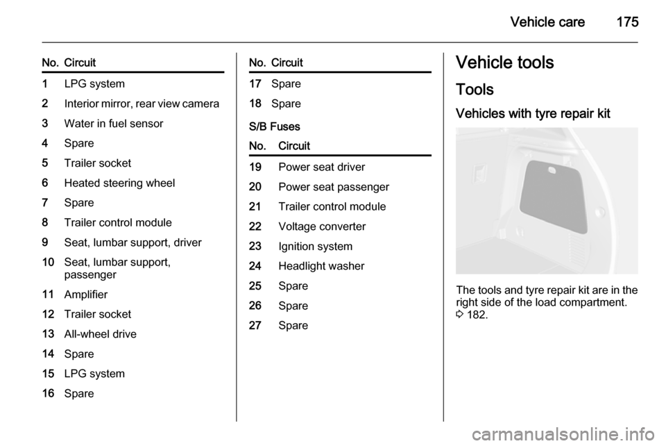
Vehicles with tyre repair kit
The tools and tyre repair kit are in the
right side of the load compartment.
3 182.
Page 184 of 223

182Vehicle careTyre chains
Use tyre chains only on front wheels.
9Warning
Damage may lead to tyre blowout.
Tyre chains are permitted on tyres of
size 195/70 R16.
Always use fine mesh chains suitable
for sport utility vehicles that add no
more than 12 mm to the tyre tread and the inboard sides (including chain
lock).
On tyres of size 215/55 R18, special
snow chains are only permitted when
they are designed with a rotating
chain belt on the tyre tread, no chain
links on the wheel inboard sides and
the chains add no more than 12 mm
to the tyre tread. For further
information regarding correct snow
chain usage for this tyre size, contact a specialized vehicle parts dealer or
snow chain manufacturer.
Tyre chains are not permitted on tyres of size 205/70 R16, 215/65 R16,
215/60 R17 and 225/45 R19.
The use of tyre chains is not permitted
on the temporary spare wheel.
Tyre repair kit
Minor damage to the tyre tread can be
repaired with the tyre repair kit.
Do not remove foreign bodies from
the tyres.
Tyre damage exceeding 4 mm or that
is at tyre's sidewall cannot be repaired with the tyre repair kit.9 Warning
Do not drive faster than 50 mph.
Do not use for a lengthy period.
Steering and handling may be
affected.
If you have a flat tyre:
Apply the parking brake and engage
first gear, reverse gear or P.
The tyre repair kit is located in the
right side of rear compartment.
Page 193 of 223
Vehicle care191
4. Switch on electrical consumers(e.g. headlights, heated rear
window) of the vehicle receiving
the jump start.
5. Reverse above sequence exactly when removing leads.Towing
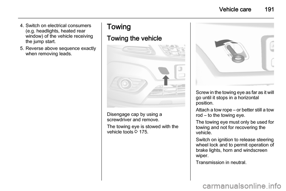
Towing the vehicle
Disengage cap by using a
screwdriver and remove.
The towing eye is stowed with the vehicle tools 3 175.
Screw in the towing eye as far as it will
go until it stops in a horizontal
position.
Attach a tow rope – or better still a tow
rod – to the towing eye.
The towing eye must only be used for towing and not for recovering the
vehicle.
Switch on ignition to release steering
wheel lock and to permit operation of
brake lights, horn and windscreen
wiper.
Transmission in neutral.
Page 220 of 223

218
Head restraints ............................ 33
Heated mirrors ............................. 28
Heated rear window ..................... 30
Heated steering wheel .................73
Heating ........................................ 37
Heating and ventilation system . 113
High beam ........................... 88, 105
Hill start assist ........................... 133
Horn ....................................... 13, 73
I
Identification plate .....................200
Ignition switch positions .............121
Immobiliser ............................ 26, 88
Indicators ...................................... 79
Information displays...................... 90
Initial drive information.................... 6
Instrument panel fuse box .........172
Instrument panel illumination control .................................... 110
Instrument panel overview ........... 10
Instrument panel storage ..............54
Interior care ............................... 195
Interior lighting ............................ 110
Interior lights ...................... 111, 170
Interior mirrors .............................. 28
Interruption of power supply ......129
Introduction .................................... 3
ISOFIX child restraint systems ....52J
Jump starting ............................. 189
K Key, memorised settings ..............21
Keys ............................................. 19
Keys, locks ................................... 19
L Lane departure warning .......86, 147
Lashing eyes ............................... 69
Lighting features .........................112
Light switch ................................ 104
Load compartment ................24, 66
Load compartment cover .............68
Load compartment fuse box ......174
Loading information .....................70
Low fuel ....................................... 88
M
Malfunction indicator light ............85
Manual anti-dazzle ......................28
Manual mode ............................. 128
Manual transmission .................. 130
Manual windows ..........................29
Memorised settings ......................21
Mirror adjustment ........................... 8
Misted light covers .....................110N
New vehicle running-in ..............121
Number plate light .....................169
O
Object detection systems ...........140
Odometer ..................................... 79
Oil, engine .......................... 198, 202
Operate pedal ............................... 85
Outside temperature ....................76
Overrun cut-off ........................... 122
P Parking ................................ 17, 124
Parking assist ............................ 140
Parking brake ............................ 132
Particulate filter ........................... 125
Performance .............................. 206
Performing work ........................157
Pollen filter ................................. 118
Power outlets ............................... 78
Power steering.............................. 86
Power steering fluid ....................160
Power windows ............................ 29
Preheating ................................... 87
Puncture ..................................... 185