dic VAUXHALL MOKKA 2015 Owner's Manual
[x] Cancel search | Manufacturer: VAUXHALL, Model Year: 2015, Model line: MOKKA, Model: VAUXHALL MOKKA 2015Pages: 223, PDF Size: 6.2 MB
Page 6 of 223
4IntroductionDanger, Warnings and
Cautions9 Danger
Text marked 9 Danger provides
information on risk of fatal injury.
Disregarding this information may
endanger life.
9 Warning
Text marked 9 Warning provides
information on risk of accident or
injury. Disregarding this
information may lead to injury.
Caution
Text marked Caution provides
information on possible damage to
the vehicle. Disregarding this
information may lead to vehicle
damage.
Symbols
Page references are indicated with 3.
3 means "see page".
Thank you for choosing a Vauxhall.
We wish you many hours of
pleasurable driving.
Your Vauxhall Team
Page 13 of 223

In brief11
1Side air vents ...................... 118
2 Light switch ......................... 104
3 Turn and lane-change
signals ................................. 109
Headlight flash ....................105
Low beam and high beam ..105
4 Cruise control ...................... 136
Speed limiter ....................... 137
Forward collision alert .........138
5 Instruments ........................... 79
6 Horn ..................................... 73
Driver airbag ........................ 44
7 Steering wheel controls .......72
8 Windscreen wiper,
windscreen washer system ...73
Rear wiper, rear washer system ................................... 75
9 Centre air vents adjustment 118
10 Centre air vents ................... 118
11 Electronic Stability Control . 134
12 Hazard warning flashers ....10913 Control indicator for airbag
deactivation .......................... 84
14 Instrument panel storage
button .................................... 54
15 Passenger airbag
deactivation ........................... 46
16 Glovebox .............................. 55
17 Infotainment system
18 Eco button for stop-start
system ................................. 122
Fuel selector ......................... 80
19 AUX input, USB input, SD
card slot
20 Selector lever, manual
transmission ....................... 130
Automatic transmission ......127
21 Parking brake ......................132
22 Power outlet .......................... 78
23 Parking assist ..................... 140
Descent control system ......... 86
24 Climate control system ........ 113
25 Accelerator pedal ................12126Ignition switch with
steering wheel lock ............121
27 Brake pedal ......................... 131
28 Clutch pedal ........................ 120
29 Steering wheel adjustment ..72
30 Instrument panel storage ......54
31 Bonnet release lever ..........158
Page 19 of 223
In brief17
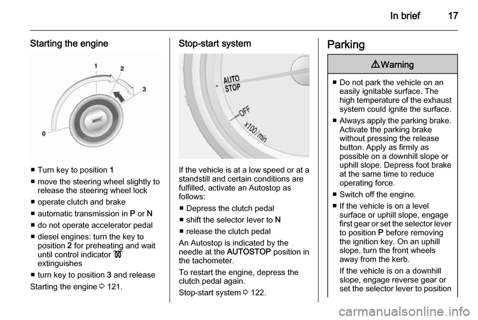
Starting the engine
■ Turn key to position 1
■ move the steering wheel slightly to release the steering wheel lock
■ operate clutch and brake
■ automatic transmission in P or N
■ do not operate accelerator pedal
■ diesel engines: turn the key to position 2 for preheating and wait
until control indicator !
extinguishes
■ turn key to position 3 and release
Starting the engine 3 121.
Stop-start system
If the vehicle is at a low speed or at a
standstill and certain conditions are
fulfilled, activate an Autostop as
follows:
■ Depress the clutch pedal
■ shift the selector lever to N
■ release the clutch pedal
An Autostop is indicated by the
needle at the AUTOSTOP position in
the tachometer.
To restart the engine, depress the
clutch pedal again.
Stop-start system 3 122.
Parking9 Warning
■ Do not park the vehicle on an
easily ignitable surface. The
high temperature of the exhaust system could ignite the surface.
■ Always apply the parking brake.
Activate the parking brake
without pressing the release
button. Apply as firmly as
possible on a downhill slope or
uphill slope. Depress foot brake
at the same time to reduce
operating force.
■ Switch off the engine.
■ If the vehicle is on a level surface or uphill slope, engage
first gear or set the selector lever
to position P before removing
the ignition key. On an uphill
slope, turn the front wheels
away from the kerb.
If the vehicle is on a downhill
slope, engage reverse gear or
set the selector lever to position
Page 28 of 223

26Keys, doors and windows
Status LED is integrated in the sensoron top of the instrument panel.
Status during the first 30 seconds of
anti-theft alarm system activation:LED illuminates=test, arming delay.LED flashes
quickly=doors, tailgate or
bonnet not
completely closed,
or system fault.
Status after system is armed:
LED flashes
slowly=system is armed.
Seek the assistance of a workshop in
the event of faults.
Deactivation
Unlocking the vehicle deactivates the anti-theft alarm system.
Alarm The alarm can be silenced bypressing any button of the radio
remote control or by switching on the
ignition.
The anti-theft alarm system can be
deactivated by pressing the button e
or switching on the ignition.
Auto door locking
If any of the doors is not opened or the position of the ignition key is not
located in position 2 or 3 3 121 within
3 minutes after unlocking doors with
the radio remote control, all doors are locked and the anti-theft alarm
system is activated automatically.
Automatic door unlocking All doors will be automatically
unlocked when impact is delivered to
impact sensors while the ignition is
switched on.
However, the doors may not be
unlocked if mechanical problems
occur with the door locking system or battery.
Immobiliser
The system is part of the ignition
switch and checks whether the
vehicle is allowed to be started with
the key being used.
The immobiliser is activated
automatically after the key has been removed from the ignition switch.If the control indicator d flashes when
the ignition is on, there is a fault in the
system; the engine cannot be started. Switch off the ignition and repeat the
start attempt.
If the control indicator continues
flashing, attempt to start the engine
using the spare key and seek the
assistance of a workshop.
Notice
The immobiliser does not lock the
doors. You should always lock the
vehicle after leaving it and switch on the anti-theft alarm system 3 21,
3 25.
Control indicator d 3 88.
Page 33 of 223
Keys, doors and windows31
Operated by pressing the Ü button.
The LED in the button indicates
activation.
Heating works with the engine
running and is switched off
automatically after a short time.
Sun visors The sun visors can be folded down orswivelled to the side to prevent
dazzling.
The sun visors mirror covers should
be closed when driving.
If the sun visors have a vanity mirror
lamp, the lamp will illuminate when
opening the vanity mirror cover.Roof
Sunroof9 Warning
Take care when operating the
sunroof. Risk of injury, particularly to children.
Keep a close eye on the movable parts when operating them.
Ensure that nothing becomes
trapped in them as they move.
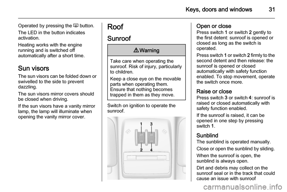
Switch on ignition to operate the
sunroof.
Open or close
Press switch 1 or switch 2 gently to
the first detent: sunroof is opened or
closed as long as the switch is
operated.
Press switch 1 or switch 2 firmly to the
second detent and then release: the
sunroof is opened or closed
automatically with safety function
enabled. To stop movement, operate
the switch once more.
Raise or close
Press switch 3 or switch 4: sunroof is
raised or closed automatically with
safety function enabled.
If the sunroof is raised, it can be
opened in one step by pressing
switch 1.
Sunblind The sunblind is operated manually.
Close or open the sunblind by sliding.
When the sunroof is open, the
sunblind is always open.
Dirt and debris may collect on the
sunroof seal or in the track that could
cause an issue with sunroof
Page 34 of 223

32Keys, doors and windows
operation, noise or plug the water
drainage system. Periodically open
the sunroof and remove any
obstacles or loose debris. Wipe the
sunroof seal and roof sealing area
using a clean cloth, mild soap, and
water. Do not remove grease from the sunroof.
General hints Safety function
If the sunroof encounters resistance
during automatic closing, it is
immediately stopped and opened
again.
Override safety function
In the event of closing difficulties due to frost or the like, press and hold
switch 2. The sunroof closes without
safety function enabled. To stop
movement, release the switch.
Initialising after a power failure
After a power failure, it may only be
possible to operate the sunroof to a
limited extent. Have the system
initialised by your workshop.
Page 39 of 223
Seats, restraints37
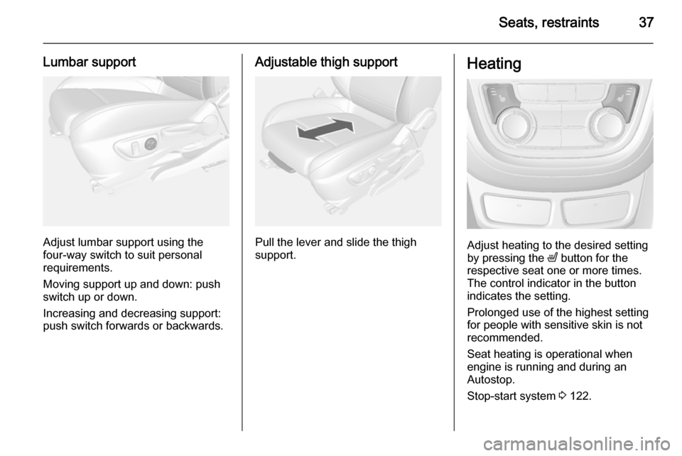
Lumbar support
Adjust lumbar support using the
four-way switch to suit personal
requirements.
Moving support up and down: push
switch up or down.
Increasing and decreasing support:
push switch forwards or backwards.
Adjustable thigh support
Pull the lever and slide the thigh
support.
Heating
Adjust heating to the desired setting
by pressing the ß button for the
respective seat one or more times.
The control indicator in the button
indicates the setting.
Prolonged use of the highest setting
for people with sensitive skin is not
recommended.
Seat heating is operational when engine is running and during an
Autostop.
Stop-start system 3 122.
Page 40 of 223
38Seats, restraintsSeat belts
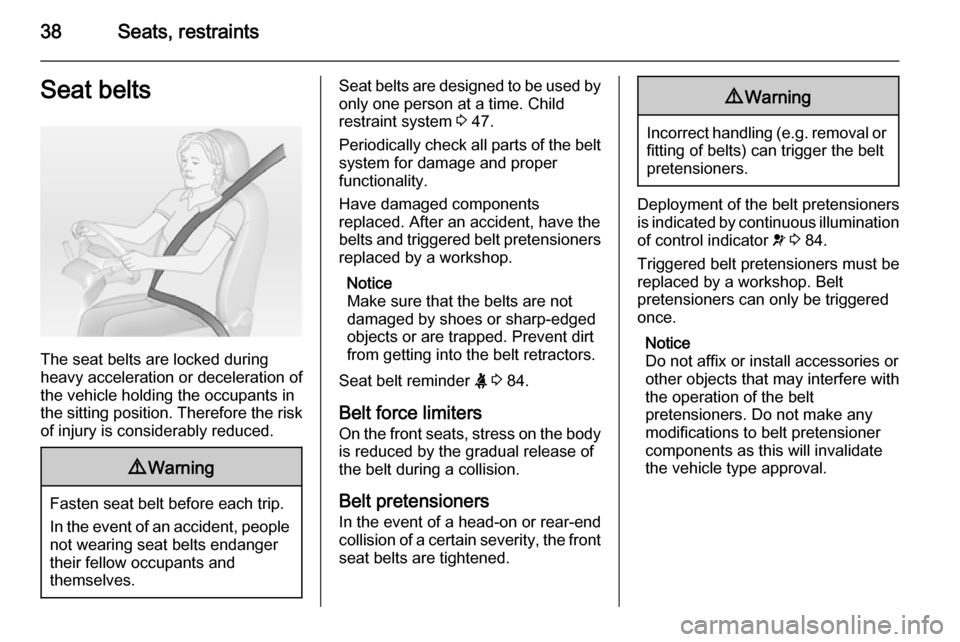
The seat belts are locked during
heavy acceleration or deceleration of
the vehicle holding the occupants in
the sitting position. Therefore the risk
of injury is considerably reduced.
9 Warning
Fasten seat belt before each trip.
In the event of an accident, people
not wearing seat belts endanger their fellow occupants and
themselves.
Seat belts are designed to be used by only one person at a time. Child
restraint system 3 47.
Periodically check all parts of the belt
system for damage and proper
functionality.
Have damaged components
replaced. After an accident, have the
belts and triggered belt pretensioners replaced by a workshop.
Notice
Make sure that the belts are not
damaged by shoes or sharp-edged
objects or are trapped. Prevent dirt
from getting into the belt retractors.
Seat belt reminder X 3 84.
Belt force limiters On the front seats, stress on the body
is reduced by the gradual release of
the belt during a collision.
Belt pretensioners In the event of a head-on or rear-end
collision of a certain severity, the front
seat belts are tightened.9 Warning
Incorrect handling (e.g. removal or
fitting of belts) can trigger the belt
pretensioners.
Deployment of the belt pretensioners
is indicated by continuous illumination
of control indicator v 3 84.
Triggered belt pretensioners must be replaced by a workshop. Belt
pretensioners can only be triggered
once.
Notice
Do not affix or install accessories or
other objects that may interfere with
the operation of the belt
pretensioners. Do not make any
modifications to belt pretensioner components as this will invalidate
the vehicle type approval.
Page 43 of 223
Seats, restraints41Airbag system
The airbag system consists of a
number of individual systems
depending on the scope of
equipment.
When triggered, the airbags inflate
within milliseconds. They also deflate
so quickly that it is often unnoticeable during the collision.9 Warning
If handled improperly the airbag
systems can be triggered in an
explosive manner.
Notice
The airbag systems and belt
pretensioner control electronics are
located in the centre console area.
Do not put any magnetic objects in
this area.
Do not affix any objects onto the
airbag covers and do not cover them with other materials.
Each airbag is triggered only once.
Have deployed airbags replaced by
a workshop. Furthermore, it may be
necessary to have the steering
wheel, the instrument panel, parts of
the panelling, the door seals,
handles and the seats replaced.
Do not make any modifications to
the airbag system as this will
invalidate the vehicle type approval.
When the airbags inflate, escaping
hot gases may cause burns.
Control indicator v for airbag systems
3 84.
Child restraint systems on front passenger seat with airbag
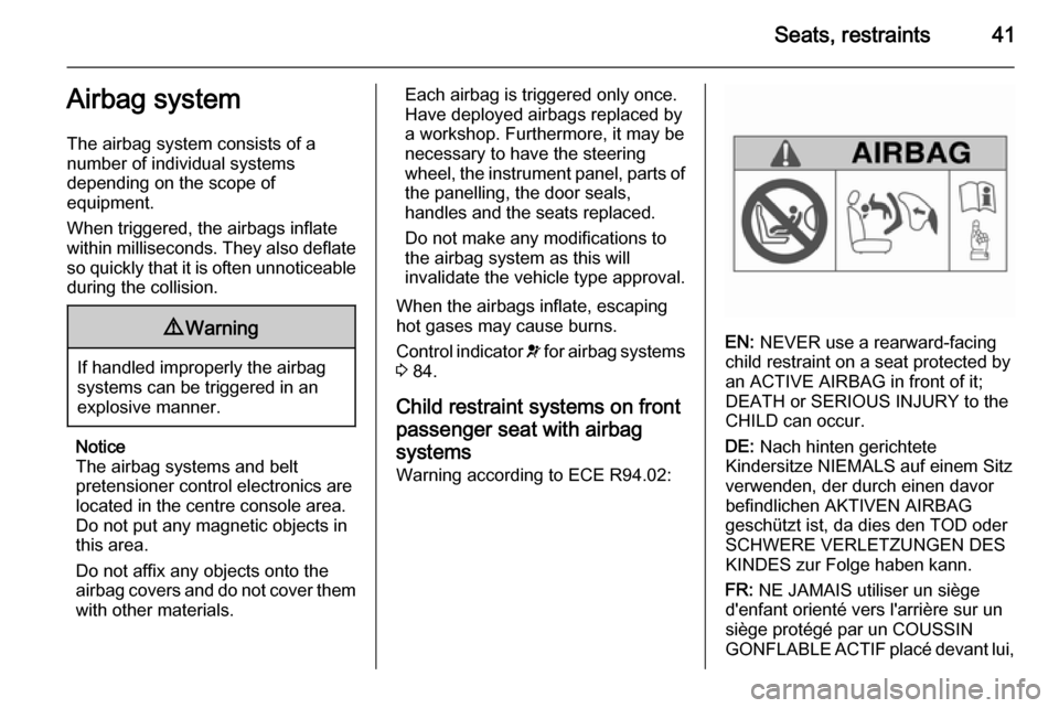
systems Warning according to ECE R94.02:
EN: NEVER use a rearward-facing
child restraint on a seat protected by
an ACTIVE AIRBAG in front of it;
DEATH or SERIOUS INJURY to the
CHILD can occur.
DE: Nach hinten gerichtete
Kindersitze NIEMALS auf einem Sitz
verwenden, der durch einen davor
befindlichen AKTIVEN AIRBAG
geschützt ist, da dies den TOD oder
SCHWERE VERLETZUNGEN DES
KINDES zur Folge haben kann.
FR: NE JAMAIS utiliser un siège
d'enfant orienté vers l'arrière sur un
siège protégé par un COUSSIN
GONFLABLE ACTIF placé devant lui,
Page 48 of 223
46Seats, restraints
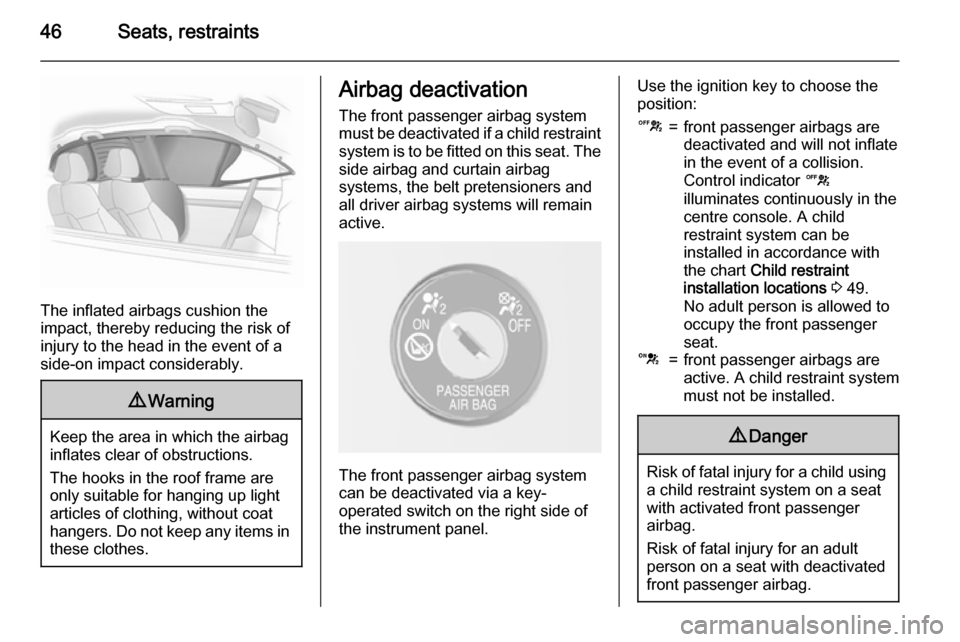
The inflated airbags cushion the
impact, thereby reducing the risk of
injury to the head in the event of a
side-on impact considerably.
9 Warning
Keep the area in which the airbag
inflates clear of obstructions.
The hooks in the roof frame are
only suitable for hanging up light
articles of clothing, without coat
hangers. Do not keep any items in these clothes.
Airbag deactivation
The front passenger airbag system
must be deactivated if a child restraint system is to be fitted on this seat. The
side airbag and curtain airbag
systems, the belt pretensioners and
all driver airbag systems will remain
active.
The front passenger airbag system
can be deactivated via a key-
operated switch on the right side of
the instrument panel.
Use the ignition key to choose theposition:c=front passenger airbags are
deactivated and will not inflate
in the event of a collision.
Control indicator c
illuminates continuously in the
centre console. A child
restraint system can be
installed in accordance with
the chart Child restraint
installation locations 3 49.
No adult person is allowed to
occupy the front passenger
seat.d=front passenger airbags are
active. A child restraint system
must not be installed.9 Danger
Risk of fatal injury for a child using
a child restraint system on a seat
with activated front passenger
airbag.
Risk of fatal injury for an adult
person on a seat with deactivated
front passenger airbag.