service indicator VAUXHALL MOKKA 2015 Owner's Manual
[x] Cancel search | Manufacturer: VAUXHALL, Model Year: 2015, Model line: MOKKA, Model: VAUXHALL MOKKA 2015Pages: 223, PDF Size: 6.2 MB
Page 83 of 223

Instruments and controls81
left area=engine operating
temperature not
yet reachedcentral area=normal operating
temperatureright area=temperature too
highCaution
If engine coolant temperature is
too high, stop vehicle, switch off
engine. Danger to engine. Check
coolant level.
Service display
The engine oil life system lets you
know when to change the engine oil
and filter. Based on driving
conditions, the interval at which an
engine oil and filter change will be
indicated can vary considerably.
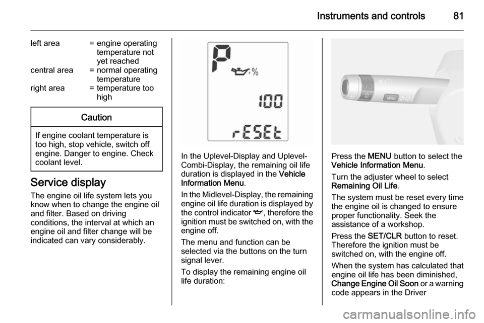
In the Uplevel-Display and Uplevel-
Combi-Display, the remaining oil life
duration is displayed in the Vehicle
Information Menu .
In the Midlevel-Display, the remaining
engine oil life duration is displayed by
the control indicator I, therefore the
ignition must be switched on, with the engine off.
The menu and function can be
selected via the buttons on the turn
signal lever.
To display the remaining engine oil
life duration:Press the MENU button to select the
Vehicle Information Menu .
Turn the adjuster wheel to select Remaining Oil Life .
The system must be reset every time
the engine oil is changed to ensure
proper functionality. Seek the
assistance of a workshop.
Press the SET/CLR button to reset.
Therefore the ignition must be
switched on, with the engine off.
When the system has calculated that
engine oil life has been diminished,
Change Engine Oil Soon or a warning
code appears in the Driver
Page 84 of 223

82Instruments and controls
Information Centre. Have engine oil
and filter changed by a workshop
within one week or 300 miles
(whichever occurs first).
Driver Information Centre 3 90.
Service information 3 197.
Control indicators The control indicators described are
not present in all vehicles. The
description applies to all instrument
versions. Depending on the
equipment, the position of the control
indicators may vary. When the
ignition is switched on, most control indicators will illuminate briefly as afunctionality test.
The control indicator colours mean:red=danger, important reminderyellow=warning, information, faultgreen=confirmation of activationblue=confirmation of activationwhite=confirmation of activation
Page 87 of 223

Instruments and controls85
* illuminates yellow.
The front passenger airbag is
deactivated 3 46.9 Danger
Risk of fatal injury for a child using
a child restraint system together
with activated front passenger
airbag.
Risk of fatal injury for an adult
person with deactivated front
passenger airbag.
Charging system
p illuminates red.
Illuminates when the ignition is
switched on and extinguishes shortly
after the engine starts.
Illuminates when the engine is
running
Stop, switch off engine. Battery is not
charging. Engine cooling may be interrupted. The brake servo unit may
cease to be effective. Seek the
assistance of a workshop.
Malfunction indicator light
Z illuminates or flashes yellow.
Illuminates when the ignition is
switched on and extinguishes shortly after the engine starts.
Illuminates when the engine is running Fault in the emission control system.
The permitted emission limits may be
exceeded. Seek the assistance of a
workshop immediately.
Flashes when the engine is
running
Fault that could lead to catalytic converter damage. Ease up on the
accelerator until the flashing stops.
Seek the assistance of a workshop
immediately.
Service vehicle soon g illuminates yellow.
Additionally a warning message or a
warning code is displayed.
The vehicle needs a service.Seek the assistance of a workshop.
Vehicle messages 3 95.
Brake and clutch system R illuminates red.
The brake and clutch fluid level is too
low 3 161.9 Warning
Stop. Do not continue your
journey. Consult a workshop.
Illuminates after the ignition is
switched on if the parking brake is
applied 3 132.
Operate pedal
- illuminates or flashes yellow.
Illuminates Clutch pedal must be depressed to
start the engine in Autostop mode.
Stop-start system 3 122.
Page 91 of 223

Instruments and controls89
Illuminates when high beam is on orduring headlight flash 3 105 , or when
high beam is on with high beam
assist, adaptive forward lighting
3 107.
Adaptive forward lighting
f illuminates or flashes yellow.
Illuminates The adaptive forward lighting system
needs a service.
Seek the assistance of a workshop.
Adaptive forward lighting 3 107.
Flashes System switched to symmetrical low
beam.
Control indicator f flashes for approx.
4 seconds after the ignition is
switched on as a reminder that the
system has been activated 3 105.
Automatic light control 3 104.
Fog light
> illuminates green.The front fog lights are on 3 109.
Rear fog light
r illuminates yellow.
The rear fog light is on 3 110.
Cruise control m illuminates white or green.
Illuminates white The system is on.
Illuminates green
Cruise control is active.
Cruise control 3 136.
Vehicle detected ahead A illuminates green.
A vehicle ahead is detected in the
same lane.
Forward collision alert 3 138.Bonnet open
/ illuminates when the bonnet is
open on vehicles with stop-start
system.
Stop-start system 3 122.
Door open h illuminates red.
A door or the tailgate is open.
Page 133 of 223

Driving and operating131Drive systems
All-wheel drive The All-Wheel Drive (AWD) system
enhances driving characteristics and stability, and helps to achieve the best possible driveability regardless of
ground surface. The system is always
active and cannot be deactivated.
The torque is distributed steplessly
between the wheels of the front and rear axle, depending on the driving
conditions. Additionally the torque
between the rear wheels is distributed
depending on the surface.
For optimum system performance,
the vehicle's tyres should not have
varying degrees of wear.
When using a temporary spare
wheel, the AWD system is
automatically disabled.
The AWD system will also be
temporarily disabled to protect the
system from overheating if there is
excessive wheel spin. When the
system cools down, AWD will be
restored.The deactivation of the AWD system
will be indicated by a message on the
Driver Information Centre.
If a service message or warning
code S73 is displayed on the Driver Information Centre, there is a
malfunction in the AWD system. Seek the assistance of a workshop.
Vehicle messages 3 95, Towing the
vehicle 3 191.Brakes
The brake system comprises two
independent brake circuits.
If a brake circuit fails, the vehicle can
still be braked using the other brake
circuit. However, braking effect is
achieved only when the brake pedal
is depressed firmly. Considerably
more force is needed for this. The
braking distance is extended. Seek the assistance of a workshop before
continuing your journey.
When the engine is not running, the
support of the brake servo unit
disappears once the brake pedal has been depressed once or twice.
Braking effect is not reduced, but
braking requires significantly greater
force. It is especially important to bear this in mind when being towed.
Control indicator R 3 85.
Antilock brake system Antilock brake system (ABS)
prevents the wheels from locking.
Page 181 of 223

Vehicle care179
If w illuminates at lower temperatures
and extinguishes after some driving,
this could be an indicator for getting
low pressure. Check tyre pressure.
Vehicle messages 3 95.
If the tyre pressure shall be reduced
or increased, switch off ignition.
Only mount wheels with pressure
sensors, otherwise the tyre pressure
will not be displayed and w
illuminates continuously.
A temporary spare wheel is not
equipped with pressure sensors. The
tyre pressure monitoring system is
not operational for these wheels.
Control indicator w illuminates. For
the further three wheels the system
remains operational.
The use of commercially available
liquid tyre repair kits can impair the
function of the system. Factory-
approved repair kits can be used.
External high-power radio equipment
could disrupt the tyre pressure
monitoring system.Each time the tyres are replaced tyre
pressure monitoring system sensors
must be dismounted and serviced. For the screwed sensor: replace
valve core and sealing ring. For
clipped sensor: replace complete
valve stem.
Vehicle loading status
Adjust tyre pressure to load condition according to tyre information label or
tyre pressure chart 3 210, and select
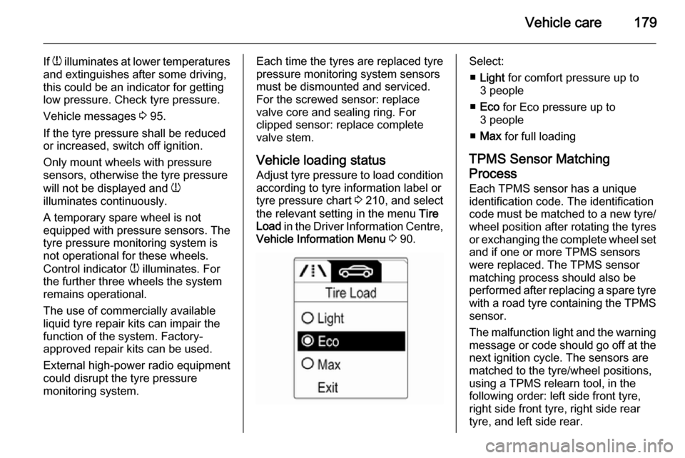
the relevant setting in the menu Tire
Load in the Driver Information Centre,
Vehicle Information Menu 3 90.Select:
■ Light for comfort pressure up to
3 people
■ Eco for Eco pressure up to
3 people
■ Max for full loading
TPMS Sensor Matching
Process
Each TPMS sensor has a unique
identification code. The identification
code must be matched to a new tyre/
wheel position after rotating the tyres
or exchanging the complete wheel set and if one or more TPMS sensors
were replaced. The TPMS sensor matching process should also be
performed after replacing a spare tyre
with a road tyre containing the TPMS
sensor.
The malfunction light and the warning
message or code should go off at the
next ignition cycle. The sensors are
matched to the tyre/wheel positions,
using a TPMS relearn tool, in the
following order: left side front tyre,
right side front tyre, right side rear
tyre, and left side rear.