light VAUXHALL MOKKA 2016 Service Manual
[x] Cancel search | Manufacturer: VAUXHALL, Model Year: 2016, Model line: MOKKA, Model: VAUXHALL MOKKA 2016Pages: 231, PDF Size: 6.55 MB
Page 149 of 231

Driving and operating147Due to the high position of the camera
the rear bumper can be seen on the
display as a guide to position.
The area displayed by the camera is
limited. The distance of the image that
appears on the display differs from
the actual distance.
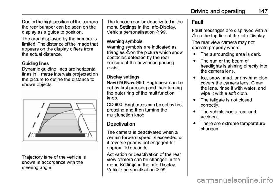
Guiding lines
Dynamic guiding lines are horizontal
lines in 1 metre intervals projected on
the picture to define the distance to
shown objects.
Trajectory lane of the vehicle is
shown in accordance with the
steering angle.
The function can be deactivated in the
menu Settings in the Info-Display.
Vehicle personalisation 3 99.
Warning symbols
Warning symbols are indicated as
triangles 9 on the picture which show
obstacles detected by the rear
sensors of the advanced parking
assist.
Display settings
Navi 650 /Navi 950 : Brightness can be
set by first pressing and then turning
the outer ring of the multifunction
knob.
CD 600 : Brightness can be set by first
pressing and then turning the
multifunction knob.
Deactivation
The camera is deactivated when a certain forward speed is exceeded or
if reverse gear is not engaged for
approx. 10 seconds.
Activation or deactivation of the rear
view camera can be changed in the menu Settings in the Info-Display.
Vehicle personalisation 3 99.Fault
Fault messages are displayed with a 9 on the top line of the Info-Display.
The rear view camera may not
operate properly when:
● The surrounding area is dark.
● The sun or the beam of headlights is shining directly into
the camera lens.
● Ice, snow, mud, or anything else covers the camera lens. Clean
the lens, rinse it with water, and
wipe it with a soft cloth.
● The tailgate is not closed correctly.
● The vehicle had a rear-end accident.
● There are extreme temperature changes.
Page 151 of 231

Driving and operating149An exclamation mark in a frame
indicates that there is an add-on sign
detected which cannot be recognised
by the system.
The system is active up to a speed of
124 mph depending on the lighting
conditions. At night the system is
active up to a speed of 99 mph.
As soon as the speed becomes
slower than 34 mph the display will be reset and the content of the traffic sign
page will be cleared. The next
recognised speed indication will be
displayed.
Display indicationTraffic signs are displayed on the
page Traffic sign detection in the
Driver Information Centre, chosen via the adjuster wheel on the turn signal
lever 3 88.
When another function in the Driver Information Centre was selected and
then Traffic sign detection page is
chosen again, the last recognised
traffic sign will be displayed.
After the traffic sign page is cleared
by the system, the following symbol is
indicated:The content of the traffic sign page is also cleared during driving by
pressing SET/CLR on the turn signal
lever for a longer time.
Pop-up function
Speed limits and no passing signs are
displayed as pop-ups on each page
of the Driver Information Centre.
Page 152 of 231

150Driving and operating
The pop-up function can be
deactivated on the traffic sign page by
pressing SET/CLR on the turn signal
lever.
Once setting page is displayed, select Off to deactivate pop-up function.
Reactivated by selecting On. When
switching on the ignition, pop-up function is deactivated.
Pop-up indication is displayed for approx. eight seconds in the Driver
Information Centre.
Fault
The traffic sign assistant system may
not operate correctly when:
● The area of the windscreen, where the front camera is
located, is not clean.
● Traffic signs are completely or partially covered or difficult to
discern.
● There are adverse environmental
conditions, e.g. heavy rain, snow,
direct sunlight or shadows. In this
case No Traffic Sign Detection
due to Weather is indicated on
the display.● Traffic signs are incorrectly mounted or damaged.
● Traffic signs do not comply with the Vienna Convention on trafficsigns (Wiener Übereinkommen
über Straßenverkehrszeichen).Caution
The system is intended to help the driver within a defined speed
range to recognise certain traffic
signs. Do not ignore traffic signs
which are not displayed by the
system.
The system does not recognise
any other than the conventional
traffic signs that might give or end
a speed limit.
Do not let this special feature
tempt you into taking risks when
driving.
Always adapt speed to the road
conditions.
The driver assistance systems do not relieve the driver from full
responsibility for vehicle
operation.
Page 153 of 231

Driving and operating151Lane departure warningThe lane departure warning system
observes the lane markings between
which the vehicle is driving via a front
camera. The system detects lane
changes and warns the driver in the
event of an unintended lane change
via visual and acoustic signals.
Criteria for the detection of an
unintended lane change are:
● no operation of turn signals
● no brake pedal operation
● no active accelerator operation or
speeding-up
● no active steering
If the driver is active, no warning will
be issued.Activation
The lane departure warning system is activated by pressing ). The
illuminated LED in the button
indicates that the system is switched
on. When the control indicator ) in
the instrument cluster illuminates
green, the system is ready to operate.
The system is only operable at
vehicle speeds above 35 mph and if
lane markings are available.
When the system recognises an
unintended lane change, the control
indicator ) changes to yellow and
flashes. Simultaneously a chime
sound is activated.
Deactivation
The system is deactivated by
pressing ), the LED in the button
extinguishes.
At speeds below 35 mph the system
is inoperable.
Fault
The lane departure warning system
may not operate properly when:
● the windscreen is not clean
● there are adverse environmental conditions like heavy rain, snow,
direct sunlight or shadows
Page 156 of 231

154Driving and operatingFill the tank completely at regular
intervals to prevent corrosion in the
tank.
Faults and remedies
If gas mode is not possible, check the following:
● Is there enough liquid gas present?
● Is there enough petrol present for
starting?
Due to extreme temperatures in
combination with the gas
composition, it may take slightly
longer before the system switches
from petrol to gas mode.
In extreme situations, the system may
also switch back to petrol mode if the
minimum requirements are not
fulfilled. If conditions allow, it might be possible to manually switch back to
liquid gas operation.
Seek the assistance of a workshop in
the event of all other faults.Caution
Repairs and adjustments may only be made by trained specialists in
order to maintain the safety and
warranty on the LPG system.
Liquid gas is given a particular odour
(odorised) so that any leaks can be
detected easily.
9 Warning
If you smell gas in the vehicle or in
the immediate vicinity, switch to petrol mode immediately. No
smoking. No naked flames or
ignition sources.
If the gas odour persists, do not start
the engine. Have the cause of the
fault remedied by a workshop.
When using underground car parks,
follow the instructions of the operator
and local laws.
Notice
In the event of an accident, switch off
the ignition and lights.
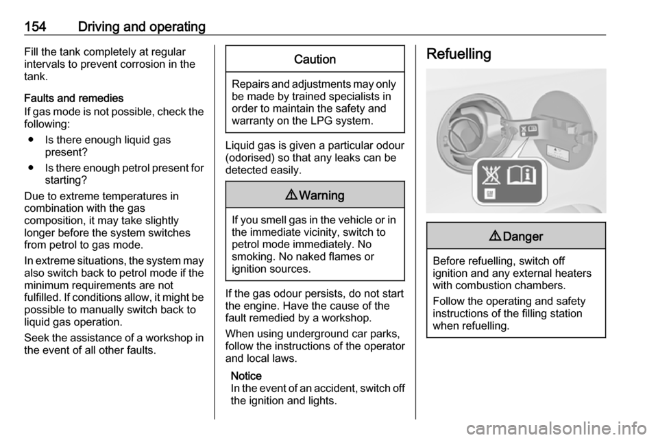
Refuelling9 Danger
Before refuelling, switch off
ignition and any external heaters
with combustion chambers.
Follow the operating and safety
instructions of the filling station
when refuelling.
Page 160 of 231

158Driving and operatingFuel consumption - CO2-
Emissions
The values for fuel consumption
(combined) of the model Vauxhall
Mokka is within a range of 37 to
69 mpg.
The values for CO 2 emission
(combined) is within a range of 158 to 109 g/km.
For the values specific to your
vehicle, refer to the EEC Certificate of
Conformity provided with your vehicle or other national registration
documents.
General information
The official fuel consumption and
specific CO 2 emission figures quoted
relate to the EU base model with
standard equipment.
Fuel consumption data and CO 2
emission data are determined
according to regulation
R (EC) No. 715/2007 (in the latest
applicable version), taking intoconsideration the vehicle weight in running order, as specified by the
regulation.
The figures are provided only for the
purpose of comparison between
different vehicle variants and must
not be taken as a guarantee for the
actual fuel consumption of a
particular vehicle. Additional
equipment may result in slightly
higher results than the stated
consumption and CO 2 figures.
Furthermore, fuel consumption is
dependent on personal driving style
as well as road and traffic conditions.Trailer hitch
General information
Only use towing equipment that has
been approved for your vehicle.
Entrust retrofitting of towing
equipment to a workshop. It may be
necessary to make changes that
affect the cooling system, heat
shields or other equipment.
The bulb outage detection function for
trailer brake light cannot detect a
partial bulb outage, e.g. in case of four times five watt bulbs, the function only
detects lamp outage when only a
single five Watt lamp remains or none remain.
Fitting of towing equipment could
cover the opening of the towing eye. If this is the case, use the coupling ball
bar for towing. Always keep the
coupling ball bar in the vehicle when
not in use.
Page 161 of 231

Driving and operating159Driving characteristics and
towing tips
Before attaching a trailer, lubricate
the coupling ball. However, do not do
so if a stabiliser, which acts on the
coupling ball, is being used to reduce snaking movements.
For trailers with low driving stability
and caravan trailers with a permitted
gross vehicle weight of more than
1000 kg a speed of 50 mph must not
be exceeded; the use of a stabiliser is
recommended.
If the trailer starts snaking, drive more
slowly, do not attempt to correct the steering and brake sharply if
necessary.
When driving downhill, drive in the
same gear as if driving uphill and
drive at a similar speed.
Adjust tyre pressure to the value
specified for full load 3 218.Trailer towing
Trailer loads
The permissible trailer loads are
vehicle and engine-dependent
maximum values which must not be
exceeded. The actual trailer load is
the difference between the actual
gross weight of the trailer and the
actual coupling socket load with the
trailer coupled.
The permissible trailer loads are
specified in the vehicle documents. In general, they are valid for gradients
up to max. 12%.
The permitted trailer loads apply up to the specified incline and up to an
altitude of 1000 metres above sea
level. Since engine power decreases
as altitude increases due to the air
becoming thinner, therefore reducing
climbing ability, the permissible gross
train weight also decreases by 10%
for every 1000 metres of additional
altitude. The gross train weight does
not have to be reduced when driving
on roads with slight inclines (less than
8%, e.g. motorways).The permissible gross train weight
must not be exceeded. This weight is specified on the identification plate3 208.
Vertical coupling load
The vertical coupling load is the load
exerted by the trailer on the coupling
ball. It can be varied by changing the
weight distribution when loading the
trailer.
The maximum permissible vertical
coupling load (75 kg) is specified on
the towing equipment identification
plate and in the vehicle documents.
Always aim for the maximum load,
especially in the case of heavy
trailers. The vertical coupling load
should never fall below 25 kg.
Rear axle load The permissible axle loads (see
identification plate or vehicle
documents) must not be exceeded.
Page 165 of 231

Vehicle care163Vehicle careGeneral Information...................164
Accessories and vehicle modifications .......................... 164
Vehicle storage ........................164
End-of-life vehicle recovery .....164
Vehicle checks ........................... 165
Performing work ......................165
Bonnet ..................................... 165
Engine oil ................................. 166
Engine coolant ......................... 167
Power steering fluid .................168
Washer fluid ............................ 168
Brakes ..................................... 169
Brake fluid ............................... 169
Vehicle battery ......................... 169
Diesel fuel system bleeding .....171
Wiper blade replacement ........171
Bulb replacement .......................172
Halogen headlights ..................172
Xenon headlights .....................174
Fog lights ................................. 175
Front turn signal lights .............175
Tail lights ................................. 176
Side turn signal lights ..............177Centre high-mounted brake
light ......................................... 177
Number plate light ...................178
Interior lights ............................ 178
Electrical system ........................179
Fuses ....................................... 179
Engine compartment fuse box . 179
Instrument panel fuse box .......181
Load compartment fuse box ....182
Vehicle tools .............................. 184
Tools ........................................ 184
Wheels and tyres .......................184
Winter tyres ............................. 184
Tyre designations ....................185
Tyre pressure .......................... 185
Tyre pressure monitoring system .................................... 186
Tread depth ............................. 189
Changing tyre and wheel size . 190 Wheel covers ........................... 190
Tyre chains .............................. 190
Tyre repair kit .......................... 191
Wheel changing .......................194
Spare wheel ............................ 196
Jump starting ............................. 198
Towing ....................................... 200
Towing the vehicle ...................200
Towing another vehicle ...........201Appearance care .......................202
Exterior care ............................ 202
Interior care ............................. 204
Page 167 of 231

Vehicle care165website, where legally required. Only
entrust this work to an authorised
recycling centre.
Gas vehicles must be recycled by a service centre authorised for gas
vehicles.Vehicle checks
Performing work9 Warning
Only perform engine compartment
checks when the ignition is off.
The cooling fan may start
operating even if the ignition is off.
9 Danger
The ignition system and Xenon
headlights use extremely high
voltage. Do not touch.
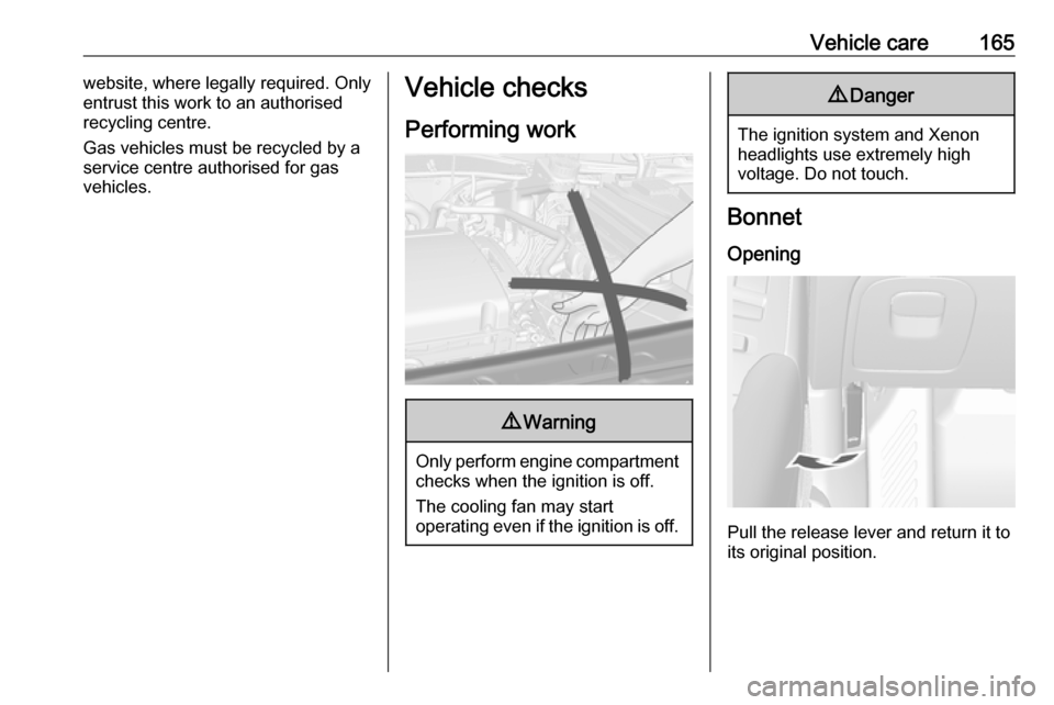
Bonnet
Opening
Pull the release lever and return it to
its original position.
Page 168 of 231

166Vehicle care
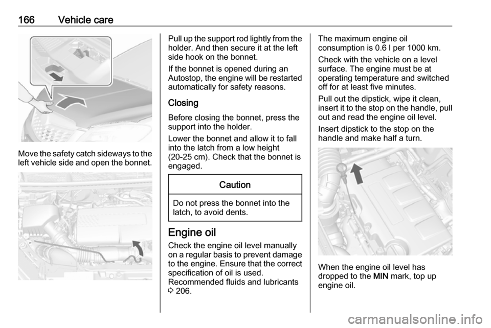
Move the safety catch sideways to theleft vehicle side and open the bonnet.
Pull up the support rod lightly from the
holder. And then secure it at the left
side hook on the bonnet.
If the bonnet is opened during an
Autostop, the engine will be restarted automatically for safety reasons.
Closing
Before closing the bonnet, press the
support into the holder.
Lower the bonnet and allow it to fall
into the latch from a low height
(20-25 cm). Check that the bonnet is
engaged.Caution
Do not press the bonnet into the
latch, to avoid dents.
Engine oil
Check the engine oil level manually
on a regular basis to prevent damage
to the engine. Ensure that the correct specification of oil is used.
Recommended fluids and lubricants
3 206.
The maximum engine oil
consumption is 0.6 l per 1000 km.
Check with the vehicle on a level
surface. The engine must be at
operating temperature and switched
off for at least five minutes.
Pull out the dipstick, wipe it clean, insert it to the stop on the handle, pull
out and read the engine oil level.
Insert dipstick to the stop on the
handle and make half a turn.
When the engine oil level has
dropped to the MIN mark, top up
engine oil.