light VAUXHALL MOKKA X 2017 Workshop Manual
[x] Cancel search | Manufacturer: VAUXHALL, Model Year: 2017, Model line: MOKKA X, Model: VAUXHALL MOKKA X 2017Pages: 245, PDF Size: 6.77 MB
Page 174 of 245

172Driving and operatingTrailer hitch
General information
Only use towing equipment that has
been approved for your vehicle.
Entrust retrofitting of towing
equipment to a workshop. It may be
necessary to make changes that
affect the cooling system, heat
shields or other equipment.
The bulb outage detection function for trailer brake light cannot detect a
partial bulb outage, e.g. in case of four
times five watt bulbs, the function only detects lamp outage when only a
single five Watt lamp remains or none
remain.
Fitting of towing equipment could
cover the opening of the towing eye.
If this is the case, use the coupling ball bar for towing. Always keep the
coupling ball bar in the vehicle when
not in use.Driving characteristics and
towing tips
Before attaching a trailer, lubricate
the coupling ball. However, do not do
so if a stabiliser, which acts on the coupling ball, is being used to reduce
snaking movements.
For trailers with low driving stability
and caravan trailers with a permitted
gross vehicle weight of more than
1000 kg a speed of 50 mph must not
be exceeded; the use of a stabiliser is
recommended.
If the trailer starts snaking, drive more
slowly, do not attempt to correct the
steering and brake sharply if
necessary.
When driving downhill, drive in the
same gear as if driving uphill and
drive at a similar speed.
Adjust tyre pressure to the value
specified for full load 3 230.Trailer towing
Trailer loadsThe permissible trailer loads are
vehicle and engine-dependent
maximum values which must not be
exceeded. The actual trailer load is
the difference between the actual
gross weight of the trailer and the
actual coupling socket load with the
trailer coupled.
The permissible trailer loads are
specified in the vehicle documents. In general, they are valid for gradients
up to max. 12%.
The permitted trailer loads apply up to
the specified incline and up to an
altitude of 1000 metres above sea
level. Since engine power decreases
as altitude increases due to the air
becoming thinner, therefore reducing
climbing ability, the permissible gross train weight also decreases by 10%
for every 1000 metres of additional
altitude. The gross train weight does
not have to be reduced when driving
on roads with slight inclines (less than
8%, e.g. motorways).
Page 178 of 245

176Vehicle careVehicle careGeneral Information...................176
Accessories and vehicle modifications .......................... 176
Vehicle storage ........................177
End-of-life vehicle recovery .....177
Vehicle checks ........................... 178
Performing work ......................178
Bonnet ..................................... 178
Engine oil ................................. 179
Engine coolant ......................... 180
Power steering fluid .................180
Washer fluid ............................ 181
Brakes ..................................... 181
Brake fluid ............................... 181
Vehicle battery ......................... 182
Diesel fuel system bleeding .....183
Wiper blade replacement ........184
Bulb replacement .......................185
Halogen headlights ..................185
Fog lights ................................. 186
Tail lights ................................. 187
Number plate light ...................188
Electrical system ........................189
Fuses ....................................... 189
Engine compartment fuse box . 189Instrument panel fuse box .......191
Load compartment fuse box ....193
Vehicle tools .............................. 194
Tools ........................................ 194
Wheels and tyres .......................195
Winter tyres ............................. 195
Tyre designations ....................195
Tyre pressure .......................... 195
Tyre pressure monitoring system .................................... 196
Tread depth ............................. 200
Changing tyre and wheel size . 201
Wheel covers ........................... 201
Tyre chains .............................. 201
Tyre repair kit .......................... 202
Wheel changing .......................205
Spare wheel ............................ 207
Jump starting ............................. 209
Towing ....................................... 211
Towing the vehicle ...................211
Towing another vehicle ...........212
Appearance care .......................213
Exterior care ............................ 213
Interior care ............................. 215General Information
Accessories and vehicle modifications
We recommend the use of genuine
parts and accessories and factory
approved parts specific for your
vehicle type. We cannot assess or
guarantee reliability of other products
- even if they have a regulatory or
otherwise granted approval.
Any modification, conversion or other
changes made to standard vehicle
specifications (including, without
limitation, software modifications,
modifications of the electronic control units) may invalidate the warrantyoffered by Vauxhall. Furthermore,
such changes may impact fuel
consumption, CO 2 emissions and
other emissions of the vehicle and
cause the vehicle to no longer
conform to the type approval,
impacting the validity of your vehicle
registration.
Page 180 of 245
178Vehicle careVehicle checks
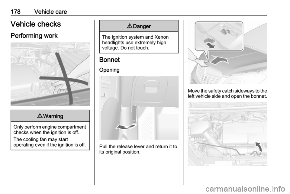
Performing work9 Warning
Only perform engine compartment
checks when the ignition is off.
The cooling fan may start
operating even if the ignition is off.
9 Danger
The ignition system and Xenon
headlights use extremely high
voltage. Do not touch.
Bonnet
Opening
Pull the release lever and return it to
its original position.
Move the safety catch sideways to the left vehicle side and open the bonnet.
Page 181 of 245
Vehicle care179Pull up the support rod lightly from the
holder. And then secure it at the left
side hook on the bonnet.
If the bonnet is opened during an
Autostop, the engine will be restarted automatically for safety reasons.
Closing
Before closing the bonnet, press the
support into the holder.
Lower the bonnet and allow it to fall
into the latch from a low height
(20-25 cm). Check that the bonnet is engaged.Caution
Do not press the bonnet into the
latch, to avoid dents.
Engine oil
Check the engine oil level manually
on a regular basis to prevent damage
to the engine. Ensure that the correct specification of oil is used.
Recommended fluids and lubricants
3 217.
The maximum engine oil
consumption is 0.6 l per 1000 km.
Check with the vehicle on a level
surface. The engine must be at
operating temperature and switched
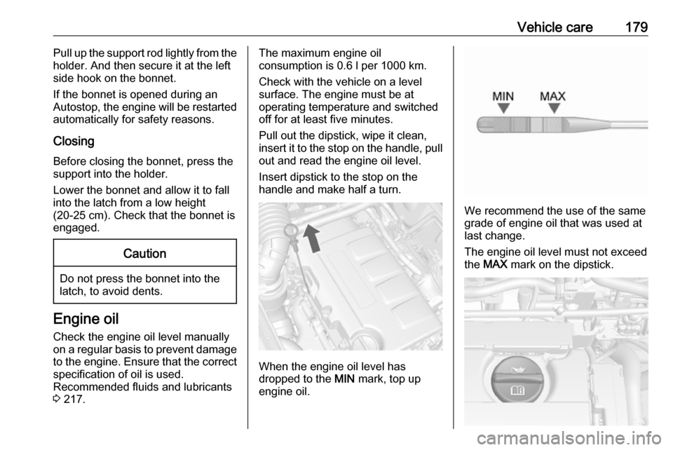
off for at least five minutes.
Pull out the dipstick, wipe it clean, insert it to the stop on the handle, pull
out and read the engine oil level.
Insert dipstick to the stop on the
handle and make half a turn.
When the engine oil level has
dropped to the MIN mark, top up
engine oil.
We recommend the use of the same
grade of engine oil that was used at
last change.
The engine oil level must not exceed
the MAX mark on the dipstick.
Page 186 of 245
184Vehicle careWiper blade replacement
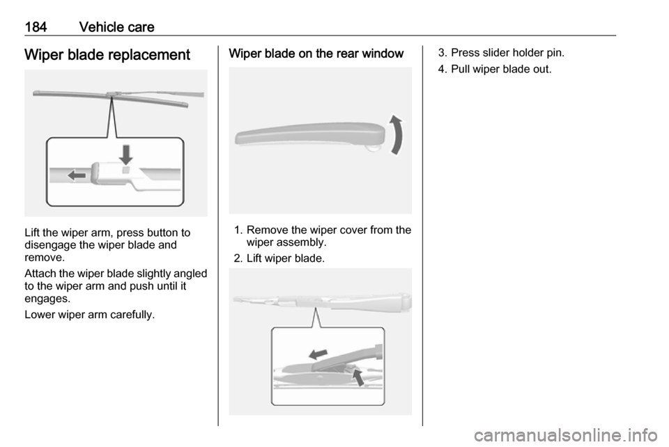
Lift the wiper arm, press button to
disengage the wiper blade and
remove.
Attach the wiper blade slightly angled
to the wiper arm and push until it
engages.
Lower wiper arm carefully.
Wiper blade on the rear window
1. Remove the wiper cover from the wiper assembly.
2. Lift wiper blade.
3. Press slider holder pin.
4. Pull wiper blade out.
Page 187 of 245
Vehicle care185Bulb replacement
Switch off the ignition and turn off the
relevant switch or close the doors.
Only hold a new bulb at the base. Do not touch the bulb glass with bare
hands.
Use only the same bulb type for
replacement.
Replace headlight bulbs from within
the engine compartment.
Notice
After driving in heavy rain or after
washing, some exterior light lenses
could appear frosty.
This condition is caused by the
temperature difference between the
inside and outside of the light.
This is similar to the condensation
on your windows inside your vehicle during the rain and doesn't indicate
a problem with your vehicle.
If the water leaks into the light bulb
circuitry, have the vehicle checked
by your authorised workshop.Halogen bulbs9 Warning
Halogen bulbs have pressurized
gas inside and can burst if you
drop or scratch the bulb. You or others could be injured. Be sure to read and follow the instructions onthe bulb package.
LED lighting
This vehicle has several LED lights.
For replacement of any LED lighting
assembly, contact a workshop.
Halogen headlights
Baselevel headlight assembly
The base model vehicle has halogen
high beam and low beam headlights,
an LED turn and lane-change signal,
a sidelight and daytime running lights on the headlight assembly.
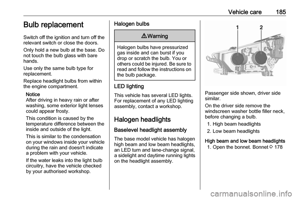
Passenger side shown, driver side
similar.
On the driver side remove the
windscreen washer bottle filler neck,
before changing a bulb.
1. High beam headlights
2. Low beam headlights
High beam and low beam headlights 1. Open the bonnet. Bonnet 3 178
Page 188 of 245
186Vehicle care
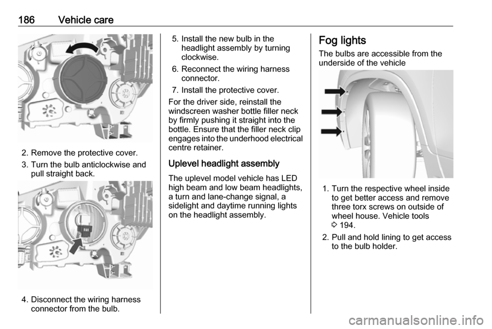
2. Remove the protective cover.
3. Turn the bulb anticlockwise and pull straight back.
4. Disconnect the wiring harnessconnector from the bulb.
5. Install the new bulb in theheadlight assembly by turning
clockwise.
6. Reconnect the wiring harness connector.
7. Install the protective cover.
For the driver side, reinstall the
windscreen washer bottle filler neck
by firmly pushing it straight into the
bottle. Ensure that the filler neck clip
engages into the underhood electrical centre retainer.
Uplevel headlight assembly The uplevel model vehicle has LED
high beam and low beam headlights, a turn and lane-change signal, asidelight and daytime running lights
on the headlight assembly.Fog lights
The bulbs are accessible from the
underside of the vehicle
1. Turn the respective wheel inside to get better access and remove
three torx screws on outside of
wheel house. Vehicle tools
3 194.
2. Pull and hold lining to get access to the bulb holder.
Page 189 of 245
Vehicle care187
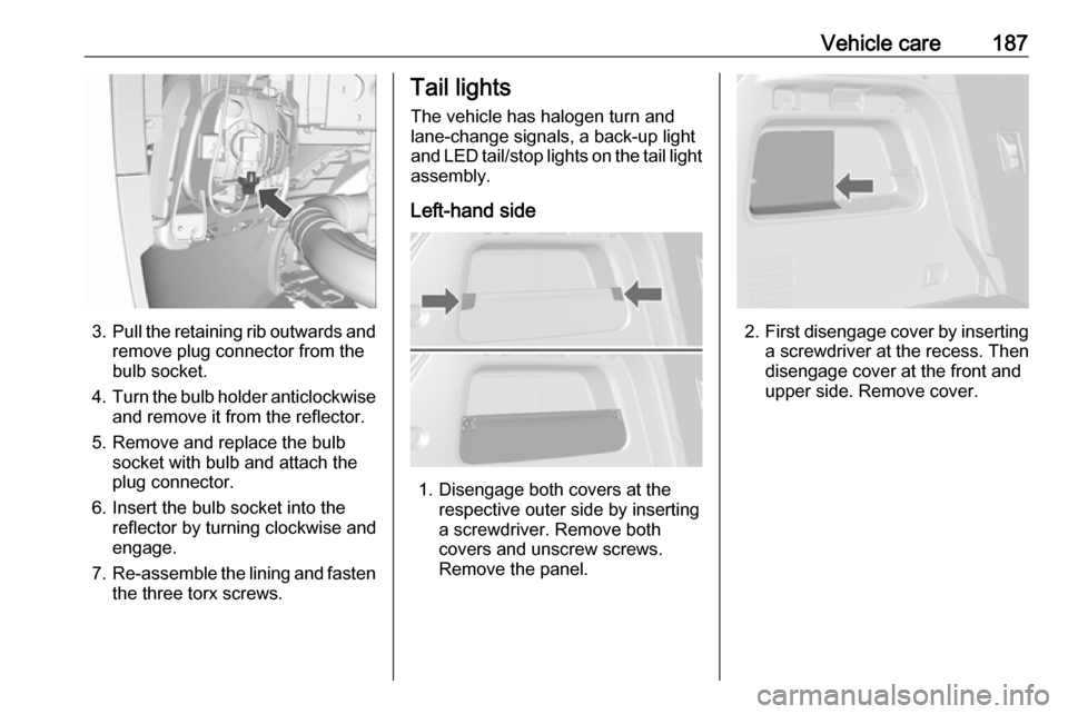
3.Pull the retaining rib outwards and
remove plug connector from the
bulb socket.
4. Turn the bulb holder anticlockwise
and remove it from the reflector.
5. Remove and replace the bulb socket with bulb and attach the
plug connector.
6. Insert the bulb socket into the reflector by turning clockwise and
engage.
7. Re-assemble the lining and fasten
the three torx screws.
Tail lights
The vehicle has halogen turn and lane-change signals, a back-up light
and LED tail/stop lights on the tail light
assembly.
Left-hand side
1. Disengage both covers at the respective outer side by inserting
a screwdriver. Remove both
covers and unscrew screws.
Remove the panel.
2. First disengage cover by inserting
a screwdriver at the recess. Then
disengage cover at the front and
upper side. Remove cover.
Page 190 of 245
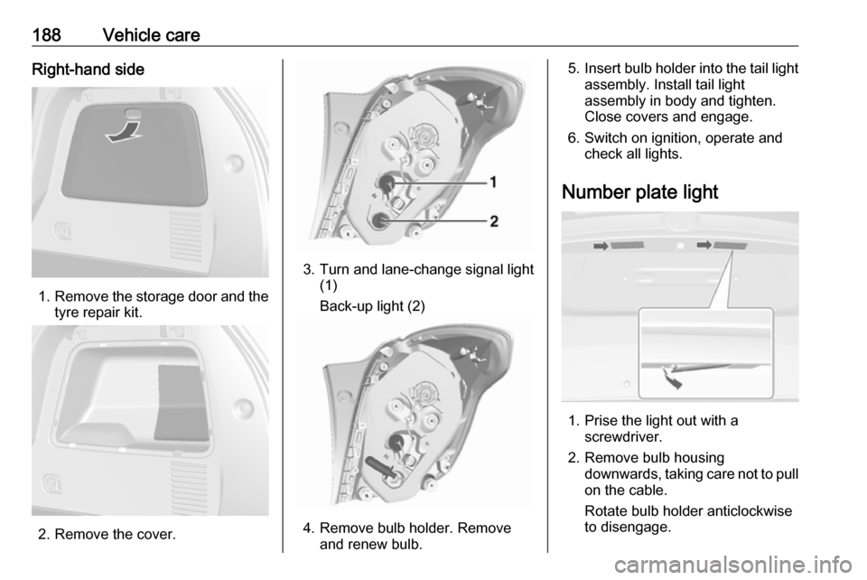
188Vehicle careRight-hand side
1.Remove the storage door and the
tyre repair kit.
2. Remove the cover.
3. Turn and lane-change signal light (1)
Back-up light (2)
4. Remove bulb holder. Remove and renew bulb.
5.Insert bulb holder into the tail light
assembly. Install tail light
assembly in body and tighten.
Close covers and engage.
6. Switch on ignition, operate and check all lights.
Number plate light
1. Prise the light out with a screwdriver.
2. Remove bulb housing downwards, taking care not to pull
on the cable.
Rotate bulb holder anticlockwise
to disengage.
Page 192 of 245
190Vehicle care
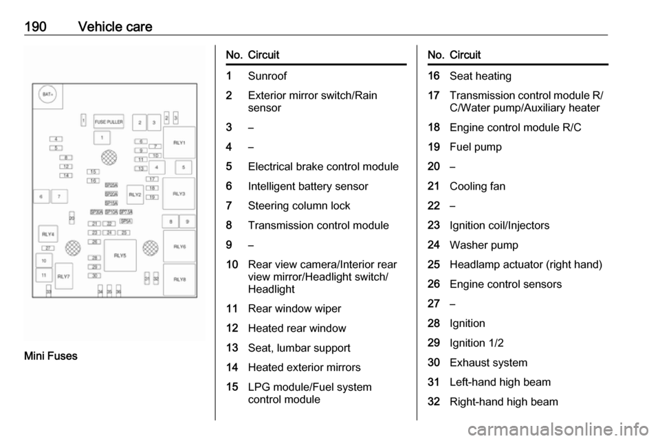
Mini Fuses
No.Circuit1Sunroof2Exterior mirror switch/Rain
sensor3–4–5Electrical brake control module6Intelligent battery sensor7Steering column lock8Transmission control module9–10Rear view camera/Interior rear
view mirror/Headlight switch/
Headlight11Rear window wiper12Heated rear window13Seat, lumbar support14Heated exterior mirrors15LPG module/Fuel system
control moduleNo.Circuit16Seat heating17Transmission control module R/ C/Water pump/Auxiliary heater18Engine control module R/C19Fuel pump20–21Cooling fan22–23Ignition coil/Injectors24Washer pump25Headlamp actuator (right hand)26Engine control sensors27–28Ignition29Ignition 1/230Exhaust system31Left-hand high beam32Right-hand high beam