display VAUXHALL MOKKA X 2018.5 Repair Manual
[x] Cancel search | Manufacturer: VAUXHALL, Model Year: 2018.5, Model line: MOKKA X, Model: VAUXHALL MOKKA X 2018.5Pages: 255, PDF Size: 7.01 MB
Page 198 of 255

196Vehicle careNo.Circuit29Info Display / Infotainment
system30Transmission control module31Instrument panel cluster32Infotainment system33Trailer socket34Passive entry / Passive start
module
S/B Fuses
No.Circuit01Power seat switch02Spare03Power windows front04Power windows rear05Logistic mode06Power seat switchNo.Circuit07Spare08Spare
Midi Fuse
No.CircuitM01PTC
Load compartment fuse box
Located in the left side of rear
compartment.
To access the fuses, remove the cover.
Page 202 of 255

200Vehicle careThe driver is responsible for correct
adjustment of tyre pressure.9 Warning
If the pressure is too low, this can
result in considerable tyre warm-
up and internal damage, leading to tread separation and even to tyre
blow-out at high speeds.
9 Warning
For specific tyres the
recommended tyre pressure as
shown in the tyre pressure table may exceed the maximum tyre
pressure as indicated on the tyre.
Never exceed the maximum tyre
pressure as indicated on the tyre.
Temperature dependency
The tyre pressure depends on the
temperature of the tyre. During
driving, tyre temperature and
pressure increase. Tyre pressure
values provided on the tyre
information label and tyre pressure
chart are valid for cold tyres, which means at 20 °C.
The pressure increases by nearly
1.5 psi for a 10 °C temperature
increase. This must be considered
when warm tyres are checked.
The tyre pressure value displayed in
the Driver Information Centre shows
the real tyre pressure. A cooled down
tyre will show a decreased value,
which does not indicate an air leak.
Tyre pressure monitoringsystem
The tyre pressure monitoring system
checks the pressure of all four tyres
once a minute when vehicle speed
exceeds a certain limit.Caution
Tyre pressure monitoring system
warns only about low tyre pressure condition and does not replace
regular tyre maintenance by the
driver.
All wheels must be equipped with pressure sensors and the tyres must
have the prescribed pressure.
Notice
In countries where the tyre pressure
monitoring system is legally
required, the use of wheels without
pressure sensors will invalidate the
vehicle operating permit.
The current tyre pressures can be
shown in the Driver Information
Centre.
Midlevel display:
Select the Tyre pressure page under
the Vehicle Information Menu ? in
the Driver Information Centre 3 95.
Page 203 of 255

Vehicle care201Uplevel display:
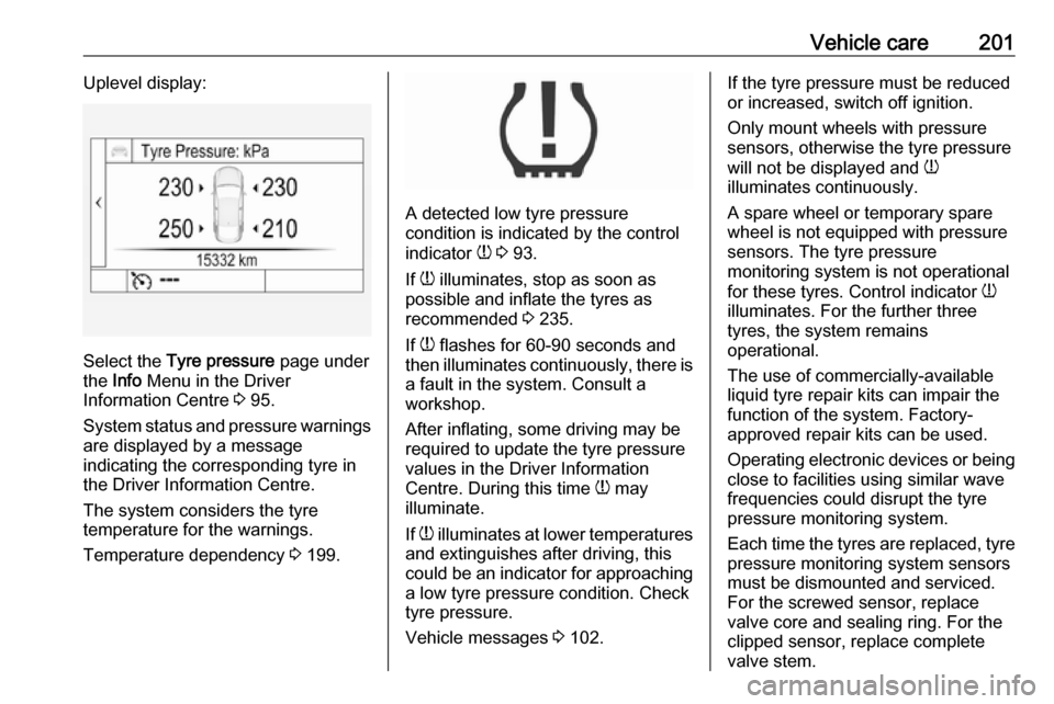
Select the Tyre pressure page under
the Info Menu in the Driver
Information Centre 3 95.
System status and pressure warnings
are displayed by a message
indicating the corresponding tyre in
the Driver Information Centre.
The system considers the tyre
temperature for the warnings.
Temperature dependency 3 199.
A detected low tyre pressure
condition is indicated by the control
indicator w 3 93.
If w illuminates, stop as soon as
possible and inflate the tyres as
recommended 3 235.
If w flashes for 60-90 seconds and
then illuminates continuously, there is a fault in the system. Consult a
workshop.
After inflating, some driving may be
required to update the tyre pressure
values in the Driver Information
Centre. During this time w may
illuminate.
If w illuminates at lower temperatures
and extinguishes after driving, this
could be an indicator for approaching
a low tyre pressure condition. Check
tyre pressure.
Vehicle messages 3 102.
If the tyre pressure must be reduced
or increased, switch off ignition.
Only mount wheels with pressure
sensors, otherwise the tyre pressure
will not be displayed and w
illuminates continuously.
A spare wheel or temporary spare
wheel is not equipped with pressure
sensors. The tyre pressure
monitoring system is not operational
for these tyres. Control indicator w
illuminates. For the further three
tyres, the system remains
operational.
The use of commercially-available
liquid tyre repair kits can impair the
function of the system. Factory-
approved repair kits can be used.
Operating electronic devices or being close to facilities using similar wave
frequencies could disrupt the tyre
pressure monitoring system.
Each time the tyres are replaced, tyre pressure monitoring system sensors
must be dismounted and serviced.
For the screwed sensor, replace
valve core and sealing ring. For the
clipped sensor, replace complete
valve stem.
Page 204 of 255

202Vehicle careVehicle loading status
Adjust tyre pressure to load condition according to tyre information label or
tyre pressure chart 3 235, and select
the appropriate setting in the menu
Tyre Load in the Driver Information
Centre, Vehicle Information Menu
3 95. This setting is the reference for
the tyre pressure warnings.
The Tyre load menu only appears
when the vehicle is at a standstill and the parking brake is applied. On
vehicles with automatic transmission
the selector lever must be in P.
Midlevel display:Select the Tyre load page under the
Vehicle Information Menu ? in the
Driver Information Centre 3 95.
● Light for comfort pressure up to
three people.
● Eco for Eco pressure up to three
people.
● Max for full loading.
Uplevel display:
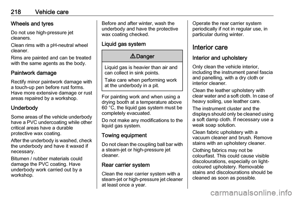
Select the Tyre load page under the
Options Menu in the Driver
Information Centre 3 95.
● Light for comfort pressure up to
three people.
● Eco for Eco pressure up to three
people.
● Max for full loading.
Tyre pressure sensor matching process
Each tyre pressure sensor has a
unique identification code. The
identification code must be matched
to a new wheel position after rotating
the wheels or exchanging the
complete wheel set and if one or more tyre pressure sensors were replaced.
The tyre pressure sensor matching
process should also be performed
after replacing a spare wheel with a
road wheel containing a tyre pressure sensor.
The malfunction light w and the
warning message should extinguish
at the next ignition cycle. The sensors
are matched to the wheel positions,
using a relearn tool, in the following
order: left side front wheel, right side
front wheel, right side rear wheel and
Page 205 of 255

Vehicle care203left side rear wheel. The turn signal
light at the current active position is
illuminated until sensor is matched.
Consult a workshop for service. There
are two minutes to match the first
wheel position, and five minutes
overall to match all four wheel
positions. If it takes longer, the
matching process stops and must be
restarted.
The tyre pressure sensor matching
process is:
1. Apply the parking brake.
2. Turn the ignition on.
3. On vehicles with automatic transmission: set the selector
lever to P.
On vehicles with manual
transmission: select neutral.
4. Press MENU on the turn signal
lever to select the Vehicle
Information Menu in the Driver
Information Centre.
5. Turn the adjuster wheel to scroll to
the tyre pressure menu.
Midlevel display:
Uplevel display:
6. Press SET/CLR to begin the
sensor matching process. A
message requesting acceptance
of the process should be
displayed.
7. Press SET/CLR again to confirm
the selection. The horn sounds
twice to signal that the receiver is
in relearn mode.
8. Start with the left side front wheel.
9. Place the relearn tool against the tyre sidewall, near the valve stem.Then press the button to activate
the tyre pressure sensor. A horn
chirp confirms that the sensor
identification code has been
matched to this tyre and wheel
position.
10. Proceed to the right side front wheel, and repeat the procedure
in Step 9.
11. Proceed to the right side rear wheel, and repeat the procedure
in Step 9.
12. Proceed to the left side rear wheel, and repeat the procedure
in Step 9. The horn sounds twice
to indicate the sensor
Page 220 of 255

218Vehicle careWheels and tyres
Do not use high-pressure jet
cleaners.
Clean rims with a pH-neutral wheel
cleaner.
Rims are painted and can be treated
with the same agents as the body.
Paintwork damageRectify minor paintwork damage witha touch-up pen before rust forms.
Have more extensive damage or rust
areas repaired by a workshop.
Underbody Some areas of the vehicle underbody
have a PVC undercoating while other
critical areas have a durable
protective wax coating.
After the underbody is washed, check the underbody and have it waxed if
necessary.
Bitumen / rubber materials could
damage the PVC coating. Have
underbody work carried out by a
workshop.Before and after winter, wash the
underbody and have the protective
wax coating checked.
Liquid gas system9 Danger
Liquid gas is heavier than air and
can collect in sink points.
Take care when performing work
at the underbody in a pit.
For painting work and when using a
drying booth at a temperature above
60 °C, the liquid gas system must be
completely evacuated.
Do not make any modifications to the
liquid gas system.
Towing equipment
Do not clean the coupling ball bar with a steam-jet or high-pressure jet
cleaner.
Rear carrier system Clean the rear carrier system with a
steam-jet or high-pressure jet cleaner
at least once a year.
Operate the rear carrier system
periodically if not in regular use, in
particular during winter.
Interior care
Interior and upholstery Only clean the vehicle interior,
including the instrument panel fascia
and panelling, with a dry cloth or
interior cleaner.
Clean the leather upholstery with
clear water and a soft cloth. In case of
heavy soiling, use leather care.
The instrument cluster and the
displays should only be cleaned using
a soft damp cloth. If necessary use a
weak soap solution.
Clean fabric upholstery with a
vacuum cleaner and brush. Remove
stains with an upholstery cleaner.
Clothing fabrics may not be
colourfast. This could cause visible
discolourations, especially on light- coloured upholstery. Removable
stains and discolourations should be
cleaned as soon as possible.
Page 222 of 255

220Service and maintenanceService and
maintenanceGeneral information ...................220
Service information ..................220
Recommended fluids, lubricants
and parts .................................... 221
Recommended fluids and lubricants ................................ 221General information
Service information In order to ensure economical and
safe vehicle operation and to
maintain the value of your vehicle, it
is of vital importance that all
maintenance work is carried out at the proper intervals as specified.
The detailed, up-to-date service
schedule for your vehicle is available
at the workshop.
Service display 3 85.
European service intervals
Maintenance of your vehicle is
required every 20,000 miles or after
one year, whichever occurs first, unless otherwise indicated in theservice display.
A shorter service interval can be valid for severe driving behaviour, e.g. for
taxis and police vehicles.
The European service intervals are
valid for the following countries:Andorra, Austria, Belgium, Bosnia-
Herzegovina, Bulgaria, Croatia,
Cyprus, Czech Republic, Denmark,
Estonia, Finland, France, Germany,
Greece, Greenland, Hungary,
Iceland, Ireland, Italy, Latvia,
Liechtenstein, Lithuania,
Luxembourg, Macedonia, Malta,
Monaco, Montenegro, Netherlands,
Norway, Poland, Portugal, Romania, San Marino, Serbia, Slovakia,
Slovenia, Spain, Sweden,
Switzerland, United Kingdom.
Service display 3 85.
International service intervals
Maintenance of your vehicle is
required every 10,000 miles or after
one year, whichever occurs first,
unless otherwise indicated in the
service display.
Severe operating conditions exist if one or more of the following
circumstances occur frequently: Cold starting, stop and go operation, trailer
operation, mountain driving, driving
on poor and sandy road surfaces,
increased air pollution, presence of
airborne sand and high dust content,
Page 223 of 255

Service and maintenance221driving at high altitude and large
variations of temperature. Under
these severe operating conditions, certain service work may be required
more frequently than the regular service interval.
The international service intervals are
valid for the countries which are not
listed in the European service
intervals.
Service display 3 85.
Confirmations
Confirmation of service is recorded in the Service and warranty booklet.
The date and mileage is completed
with the stamp and signature of the
servicing workshop.
Make sure that the Service and
warranty booklet is completed
correctly as continuous proof of
service is essential if any warranty or
goodwill claims are to be met, and is
also a benefit when selling the
vehicle.Service interval with remaining
engine oil life duration
The service interval is based on
several parameters depending on
usage.
The service display lets you know when to change the engine oil.
Service display 3 85.Recommended fluids,
lubricants and parts
Recommended fluids andlubricants
Only use products that meet the
recommended specifications.9 Warning
Operating materials are
hazardous and could be
poisonous. Handle with care. Pay
attention to information given on
the containers.
Engine oil
Engine oil is identified by its quality
and its viscosity. Quality is more
important than viscosity when
selecting which engine oil to use. The oil quality ensures e.g. engine
cleanliness, wear protection and oil
aging control, whereas viscosity
grade gives information on the oil's
thickness over a temperature range.
Page 245 of 255

Customer information243EnGIS Technologies, Inc.
BringGo ®
is a registered trademark of
EnGIS Technologies, Inc.Google Inc.
Android™ and Google Play™ Store
are trademarks of Google Inc.Stitcher Inc.
Stitcher™ is a trademark of Stitcher,
Inc.Verband der Automobilindustrie e.V.
AdBlue ®
is a registered trademark of
the VDA.Vehicle data recording
and privacy
Event data recorders
Electronic control units are installed in
your vehicle. Control units process
data which is received by vehicle
sensors, for example, or which they
generate themselves or exchange
amongst themselves. Some control
units are necessary for the safe
functioning of your vehicle, others
assist you while you drive (driver
assistance systems), while others
provide comfort or infotainment
functions.
Operating data in the vehicle Control units process data for
operation of the vehicle.This data includes, for example:
● Vehicle status information (e.g. wheel rotation rate, speed,
movement delay, lateral
acceleration, "seatbelts
fastened" display),
● Ambient conditions (e.g. temperature, rain sensor,
distance sensor).
Most of this data is volatile and is
processed only in the vehicle itself,
and not beyond the operating time.
Moreover, many control units include
data storage device (amongst others the vehicle key). This is used to allow
information to be documented
temporarily or permanently on vehicle
condition, component stress,
maintenance requirements and
technical events and errors.
The following information, for
example, is stored:
● System component operating states (e.g. fill level, tyre
pressure, battery status),
● State of charge of the high voltage battery, estimated range(in the case of electric vehicles),
Page 252 of 255

250Head restraint adjustment .............8
Head restraints ............................ 37
Heated mirrors ............................. 32
Heated rear window ..................... 35
Heated steering wheel .................75
Heating ........................................ 41
Heating and ventilation system . 125
High beam ........................... 94, 115
High beam assist ..................94, 116
Hill start assist ........................... 151
Horn ....................................... 13, 76
I
Identification plate .....................224
Ignition switch positions .............134
Immobiliser ............................ 30, 94
Indicators ...................................... 82
Info Display ................................... 99
Information displays...................... 95
Initial drive information.................... 6
Instrument panel fuse box .........194
Instrument panel illumination control .................................... 122
Instrument panel overview ........... 10
Interior care ............................... 218
Interior lighting ............................ 122
Interior lights .............................. 122
Interior mirrors .............................. 32
Interruption of power supply ......147
Introduction .................................... 3J
Jump starting ............................. 212
K Key, memorised settings ..............22
Keys ............................................. 19
Keys, locks ................................... 19
L Lane departure warning .......92, 167
Lashing eyes ............................... 71
Lighting features .........................123
Light switch ................................ 114
Load compartment ................28, 69
Load compartment cover .............70
Load compartment fuse box ......196
Loading information .....................72
Low fuel ....................................... 93
LPG .............................. 84, 170, 226
M Malfunction indicator light ............91
Manual anti-dazzle ......................32
Manual mode ............................. 146
Manual transmission .................. 148
Manual windows ..........................33
Memorised settings ......................22
Midlevel display ............................ 95
Mirror adjustment ........................... 8 Misted light covers .....................122N
New vehicle running-in ..............133
Number plate light .....................191
O Object detection systems ...........160
Odometer ..................................... 82
Oil, engine .......................... 221, 226
OnStar ........................................ 108
Outside temperature ....................78
Overrun cut-off ........................... 137
P Parking ................................ 18, 139
Parking assist ............................ 160
Parking brake ............................ 150
Particulate filter ........................... 141
Performance .............................. 231
Performing work ........................181
Pollen filter ................................. 130
Power button .............................. 134
Power outlets ............................... 81
Power steering fluid ....................183
Power windows ............................ 33
Preheating ................................... 93
Puncture ..................................... 208
R Radio Frequency Identification (RFID) ..................................... 246
Radio remote control ...................20