Light VAUXHALL MOKKA X 2019 Repair Manual
[x] Cancel search | Manufacturer: VAUXHALL, Model Year: 2019, Model line: MOKKA X, Model: VAUXHALL MOKKA X 2019Pages: 253, PDF Size: 7.09 MB
Page 189 of 253

Vehicle care187Rear window
1. Remove the wiper cover from thewiper assembly.
2. Lift wiper blade.
3. Press slider holder pin.
4. Pull wiper blade out.Bulb replacement
Switch off the ignition and turn off the
relevant switch or close the doors.
Only hold a new bulb at the base. Do not touch the bulb glass with bare
hands.
Use only the same bulb type for
replacement.
Replace headlight bulbs from within
the engine compartment.
Notice
After driving in heavy rain or after
washing, some exterior light lenses
could appear frosty.
This condition is caused by the
temperature difference between the
inside and outside of the light.
This is similar to the condensation
on your windows inside your vehicle
during the rain and doesn't indicate
a problem with your vehicle.
If the water leaks into the light bulb
circuitry, have the vehicle checked
by your authorised workshop.
Page 190 of 253

188Vehicle careHalogen bulbs9Warning
Halogen bulbs have pressurized
gas inside and can burst if you
drop or scratch the bulb. You or others could be injured. Be sure to read and follow the instructions onthe bulb package.
LED lighting
This vehicle has several LED lights.
For replacement of any LED lighting
assembly, contact a workshop.
Halogen headlights
Baselevel headlight assembly
The base model vehicle has halogen
high beam and low beam headlights,
LED turn lights, a sidelight and
daytime running lights on the
headlight assembly.
Passenger side shown, driver side
similar.
On the driver side remove the
windscreen washer bottle filler neck,
before changing a bulb.
1. High beam headlights
2. Low beam headlights
High beam and low beam headlights 1. Open the bonnet.
Bonnet 3 181.2. Remove the protective cover.
3. Turn the bulb anticlockwise and pull straight back.
4. Disconnect the wiring harnessconnector from the bulb.
Page 191 of 253

Vehicle care1895. Install the new bulb in theheadlight assembly by turning
clockwise.
6. Reconnect the wiring harness connector.
7. Install the protective cover.
For the driver side, reinstall the
windscreen washer bottle filler neck
by firmly pushing it straight into the
bottle. Ensure that the filler neck clip
engages into the underhood electrical
centre retainer.
Uplevel headlight assembly
The uplevel model vehicle has LED high beam and low beam headlights,
turn lights, a sidelight and daytime
running lights on the headlight
assembly.Front fog lights
The bulbs are accessible from the
underside of the vehicle
1. Turn the respective wheel inside to get better access and remove
three torx screws on outside of
wheel house.
Vehicle tools 3 197.
2. Pull and hold lining to get access to the bulb holder.
3.Pull the retaining rib outwards and
remove plug connector from the
bulb socket.
4. Turn the bulb holder anticlockwise
and remove it from the reflector.
5. Remove and replace the bulb socket with bulb and attach the
plug connector.
6. Insert the bulb socket into the reflector by turning clockwise and
engage.
7. Re-assemble the lining and fasten
the three torx screws.
Page 192 of 253

190Vehicle careTail lightsLeft-hand side
1. Disengage both covers at the respective outer side by inserting
a screwdriver. Remove both
covers and unscrew screws.
Remove the panel.
2. First disengage cover by inserting
a screwdriver at the recess. Then
disengage cover at the front and
upper side. Remove cover.
Right-hand side
1. Remove the storage door and the
tyre repair kit.
2. Remove the cover.
Page 193 of 253

Vehicle care191
3. Tail / stop light, if not equippedwith LEDs (1)
Turn light (2)
Back-up light (3)
4. Remove bulb holder. Remove and renew bulb.
5. Insert bulb holder into the tail light
assembly. Install tail light
assembly in body and tighten.
Close covers and engage.
6. Switch on ignition, operate and check all lights.
Number plate light
1. Prise the light out with a screwdriver.
2. Remove bulb housing downwards, taking care not to pull
on the cable.
Rotate bulb holder anticlockwise
to disengage.
3. Remove bulb from holder and renew bulb.
4. Insert bulb holder in bulb housing and rotate clockwise.
5. Insert bulb housing and secure using a screwdriver.
Rear fog light
The bulbs are accessible from the
underside of the vehicle.
Page 195 of 253
Vehicle care193Fuse extractorA fuse extractor may be located in the fuse box in the engine compartment.
Place the fuse extractor on the
various types of use from the top or
side, and withdraw fuse.
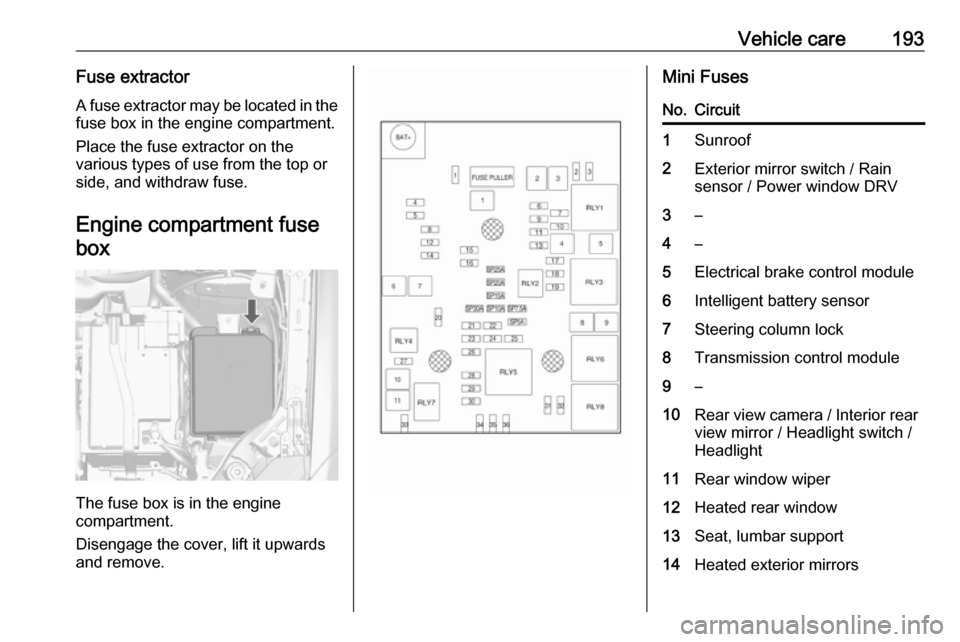
Engine compartment fusebox
The fuse box is in the engine
compartment.
Disengage the cover, lift it upwards
and remove.
Mini FusesNo.Circuit1Sunroof2Exterior mirror switch / Rain
sensor / Power window DRV3–4–5Electrical brake control module6Intelligent battery sensor7Steering column lock8Transmission control module9–10Rear view camera / Interior rear
view mirror / Headlight switch /
Headlight11Rear window wiper12Heated rear window13Seat, lumbar support14Heated exterior mirrors
Page 196 of 253
194Vehicle careNo.Circuit15LPG module / Fuel system
control module16Seat heating17Transmission control module R/ C / Water pump / Auxiliary
heater18Engine control module R/C19Fuel pump20–21Cooling fan22–23Ignition coil / Injectors24Washer pump25Headlamp actuator26Engine control sensors27–28Ignition29Ignition 1/2No.Circuit30Exhaust system31Left-hand high beam32Right-hand high beam33Engine control module34Horn35Air conditioning system36Front fog light
J-cases Fuses
No.Circuit1Electrical brake control module2Front wiper3Linear power module4Power terminal of instrument
panel fuse box5–6Fuel heater7StarterNo.Circuit8Cooling fan9Cooling fan10Engine control module / Glow
plug11Starter
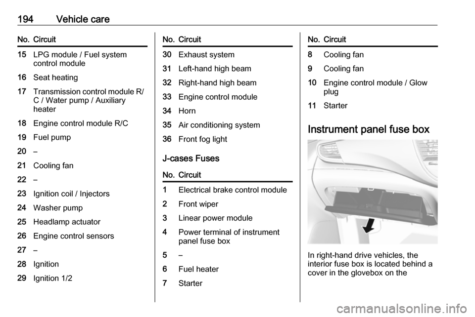
Instrument panel fuse box
In right-hand drive vehicles, the
interior fuse box is located behind a
cover in the glovebox on the
Page 197 of 253
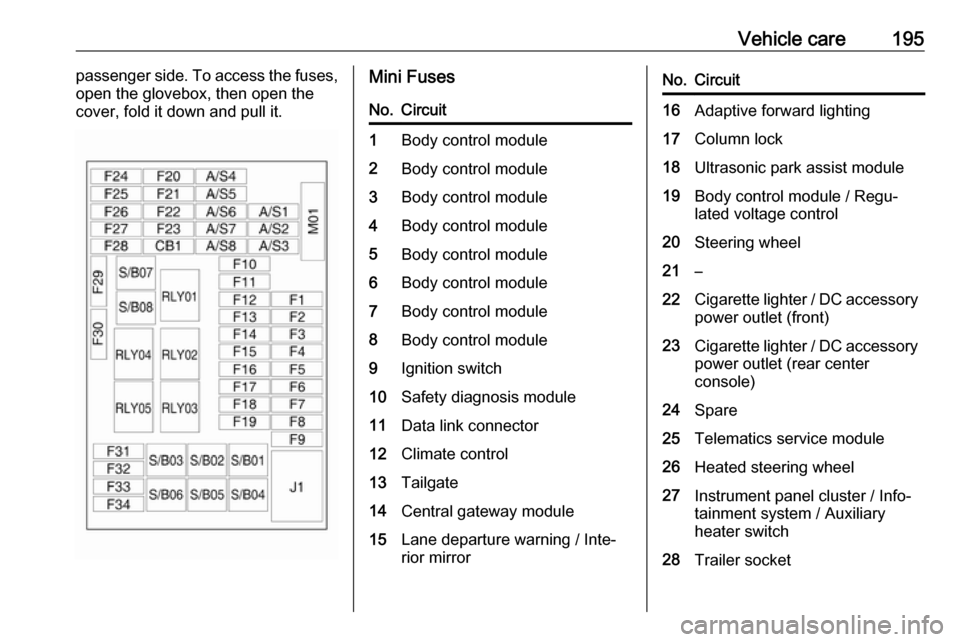
Vehicle care195passenger side. To access the fuses,
open the glovebox, then open the
cover, fold it down and pull it.Mini FusesNo.Circuit1Body control module2Body control module3Body control module4Body control module5Body control module6Body control module7Body control module8Body control module9Ignition switch10Safety diagnosis module11Data link connector12Climate control13Tailgate14Central gateway module15Lane departure warning / Inte‐
rior mirrorNo.Circuit16Adaptive forward lighting17Column lock18Ultrasonic park assist module19Body control module / Regu‐
lated voltage control20Steering wheel21–22Cigarette lighter / DC accessory
power outlet (front)23Cigarette lighter / DC accessory power outlet (rear center
console)24Spare25Telematics service module26Heated steering wheel27Instrument panel cluster / Info‐
tainment system / Auxiliary
heater switch28Trailer socket
Page 204 of 253
202Vehicle careVehicle loading status
Adjust tyre pressure to load condition according to tyre information label or
tyre pressure chart 3 234, and select
the appropriate setting in the menu
Tyre Load in the Driver Information
Centre, Vehicle Information Menu
3 96. This setting is the reference for
the tyre pressure warnings.
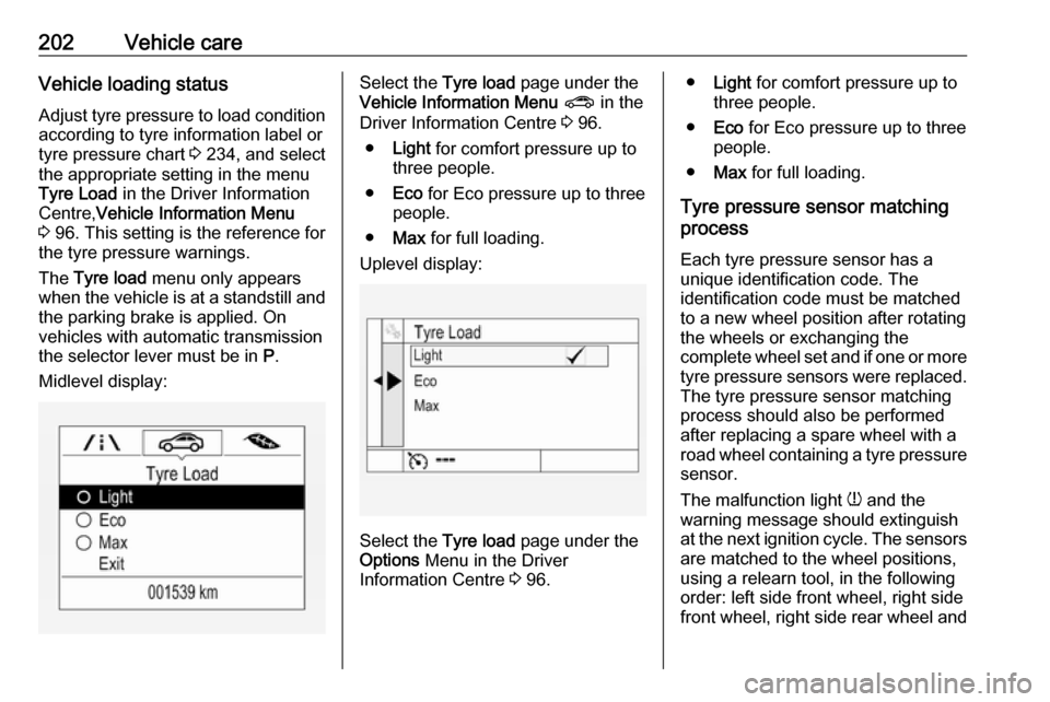
The Tyre load menu only appears
when the vehicle is at a standstill and the parking brake is applied. On
vehicles with automatic transmission
the selector lever must be in P.
Midlevel display:Select the Tyre load page under the
Vehicle Information Menu ? in the
Driver Information Centre 3 96.
● Light for comfort pressure up to
three people.
● Eco for Eco pressure up to three
people.
● Max for full loading.
Uplevel display:
Select the Tyre load page under the
Options Menu in the Driver
Information Centre 3 96.
● Light for comfort pressure up to
three people.
● Eco for Eco pressure up to three
people.
● Max for full loading.
Tyre pressure sensor matching process
Each tyre pressure sensor has a
unique identification code. The
identification code must be matched
to a new wheel position after rotating
the wheels or exchanging the
complete wheel set and if one or more tyre pressure sensors were replaced.
The tyre pressure sensor matching
process should also be performed
after replacing a spare wheel with a
road wheel containing a tyre pressure sensor.
The malfunction light w and the
warning message should extinguish
at the next ignition cycle. The sensors
are matched to the wheel positions,
using a relearn tool, in the following
order: left side front wheel, right side
front wheel, right side rear wheel and
Page 205 of 253
Vehicle care203left side rear wheel. The turn signal
light at the current active position is
illuminated until sensor is matched.
Consult a workshop for service. There
are two minutes to match the first
wheel position, and five minutes
overall to match all four wheel
positions. If it takes longer, the
matching process stops and must be
restarted.
The tyre pressure sensor matching
process is:
1. Apply the parking brake.
2. Turn the ignition on.
3. On vehicles with automatic transmission: set the selector
lever to P.
On vehicles with manual
transmission: select neutral.
4. Press MENU on the turn signal
lever to select the Vehicle
Information Menu in the Driver
Information Centre.
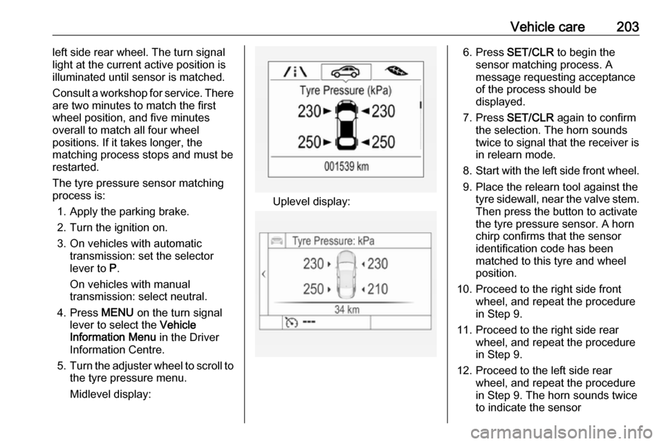
5. Turn the adjuster wheel to scroll to
the tyre pressure menu.
Midlevel display:
Uplevel display:
6. Press SET/CLR to begin the
sensor matching process. A
message requesting acceptance
of the process should be
displayed.
7. Press SET/CLR again to confirm
the selection. The horn sounds
twice to signal that the receiver is
in relearn mode.
8. Start with the left side front wheel.
9. Place the relearn tool against the tyre sidewall, near the valve stem.Then press the button to activate
the tyre pressure sensor. A horn
chirp confirms that the sensor
identification code has been
matched to this tyre and wheel
position.
10. Proceed to the right side front wheel, and repeat the procedure
in Step 9.
11. Proceed to the right side rear wheel, and repeat the procedure
in Step 9.
12. Proceed to the left side rear wheel, and repeat the procedure
in Step 9. The horn sounds twice
to indicate the sensor