tyre pressure VAUXHALL MOVANO_B 2014 Owner's Manual
[x] Cancel search | Manufacturer: VAUXHALL, Model Year: 2014, Model line: MOVANO_B, Model: VAUXHALL MOVANO_B 2014Pages: 201, PDF Size: 4.74 MB
Page 18 of 201
16In brief
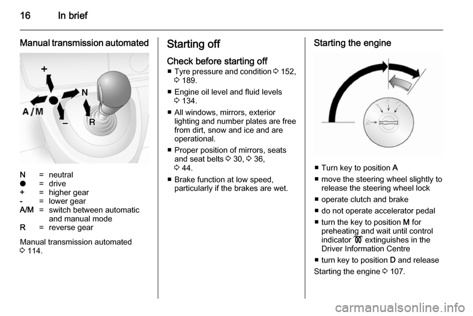
Manual transmission automatedN=neutralo=drive+=higher gear-=lower gearA/M=switch between automatic
and manual modeR=reverse gear
Manual transmission automated
3 114.
Starting off
Check before starting off ■ Tyre pressure and condition 3 152,
3 189.
■ Engine oil level and fluid levels 3 134.
■ All windows, mirrors, exterior lighting and number plates are free
from dirt, snow and ice and are
operational.
■ Proper position of mirrors, seats and seat belts 3 30, 3 36,
3 44.
■ Brake function at low speed, particularly if the brakes are wet.Starting the engine
■ Turn key to position A
■ move the steering wheel slightly to release the steering wheel lock
■ operate clutch and brake
■ do not operate accelerator pedal
■ turn the key to position M for
preheating and wait until control
indicator ! extinguishes in the
Driver Information Centre
■ turn key to position D and release
Starting the engine 3 107.
Page 69 of 201

Storage679Warning
Always make sure that the load in
the vehicle is securely stowed.
Otherwise objects can be thrown
around inside the vehicle and
cause personal injury or damage
to the load or car.
■ The payload is the difference between the permitted gross
vehicle weight (see identification
plate 3 171) and the EC kerb
weight.
To calculate the EC kerb weight,
enter the data for your vehicle in the
Weights table at the front of this
manual.
The EC kerb weight includes
weights for the driver (68 kg),
luggage (7 kg) and all fluids (tank
90% full).
Optional equipment and
accessories increase the kerb
weight.
■ Driving with a roof load increases the sensitivity of the vehicle to
cross-winds and has a detrimental
effect on vehicle handling due to
the vehicle's higher centre of
gravity. Distribute the load evenly
and secure it properly with retaining
straps. Adjust the tyre pressure and vehicle speed according to the load
conditions. Check and retighten the straps frequently.
Do not drive faster than 75 mph.
■ The permissible roof load (which includes the weight of the roof rack)
is 200 kg for standard roof variants.
The roof load is the combined
weight of the roof rack and the load.
Page 121 of 201
Driving and operating119Parking brake
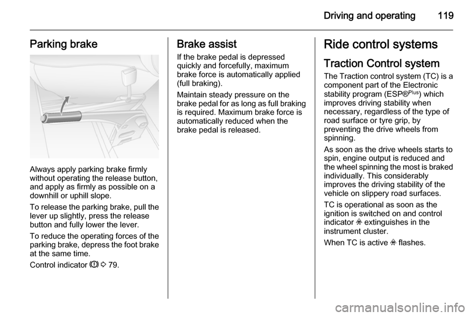
Always apply parking brake firmly
without operating the release button,
and apply as firmly as possible on a
downhill or uphill slope.
To release the parking brake, pull the lever up slightly, press the release
button and fully lower the lever.
To reduce the operating forces of the
parking brake, depress the foot brake
at the same time.
Control indicator R 3 79.
Brake assist
If the brake pedal is depressed
quickly and forcefully, maximum
brake force is automatically applied
(full braking).
Maintain steady pressure on the
brake pedal for as long as full braking
is required. Maximum brake force is
automatically reduced when the
brake pedal is released.Ride control systems
Traction Control system
The Traction control system (TC) is a
component part of the Electronic
stability program (ESP® Plus
) which
improves driving stability when
necessary, regardless of the type of
road surface or tyre grip, by
preventing the drive wheels from
spinning.
As soon as the drive wheels starts to spin, engine output is reduced and
the wheel spinning the most is braked individually. This considerably
improves the driving stability of the
vehicle on slippery road surfaces.
TC is operational as soon as the
ignition is switched on and control
indicator v extinguishes in the
instrument cluster.
When TC is active v flashes.
Page 131 of 201

Driving and operating129Trailer hitch
General information
Only use towing equipment that has
been approved for your vehicle.
Entrust fitting of towing equipment at
a later date to a workshop. It may be
necessary to make changes that
affect the cooling system, heat
shields or other equipment.
Driving characteristics and
towing tips In the case of trailers with brakes,
attach the breakaway stopping cable.
Before attaching a trailer, lubricate
the coupling ball. However, do not do
so if a stabiliser, which acts on the
coupling ball, is being used to reduce snaking movements. For trailers with
low driving stability the use of a
stabiliser is recommended.
A maximum speed of 50 mph must
not be exceeded, even in countries
where higher speeds are permitted.If the trailer starts snaking, drive more
slowly, do not attempt to correct the
steering and brake sharply if
necessary.
When driving downhill, drive in the
same gear as if driving uphill and
drive at a similar speed.
Adjust tyre pressure to the value
specified for full load 3 189.
Trailer towing Trailer loads
The permissible trailer loads are
vehicle-dependent and engine-
dependent maximum values which
must not be exceeded. The actual trailer load is the difference between
the actual gross weight of the trailer
and the actual coupling socket load
with the trailer coupled.
The permissible trailer loads are
specified in the vehicle documents. In general, they are valid for gradients
up to max. 12 %.
The permitted trailer load applies up to the specified incline and up to an
altitude of 1000 metres above sealevel. Since engine power decreases
as altitude increases due to the air
becoming thinner, therefore reducing
climbing ability, the permissible gross
train weight also decreases by 10 %
for every 1000 metres of additional
altitude. The gross train weight does
not have to be reduced when driving
on roads with slight inclines (less than
8 %, e.g. motorways).
The permissible gross train weight
must not be exceeded. This weight is
specified on the identification plate
3 171.
Vertical coupling load
The vertical coupling load is the load
exerted by the trailer on the coupling
ball. It can be varied by changing the
weight distribution when loading the
trailer.
The maximum permissible vertical
coupling load is specified on the
towing equipment identification plate
and in the vehicle documents. Always aim for the maximum load, especially
in the case of heavy trailers. The
vertical coupling load should never
fall below 25 kg.
Page 134 of 201

132Vehicle careVehicle careGeneral Information...................132
Vehicle checks ........................... 133
Bulb replacement .......................140
Electrical system ........................148
Vehicle tools .............................. 150
Wheels and tyres .......................151
Jump starting ............................. 160
Towing ....................................... 162
Appearance care .......................164General Information
Accessories and vehicle
modifications
We recommend the use of genuine parts and accessories and factory
approved parts specific for your
vehicle type. We cannot assess or
guarantee reliability of other products
- even if they have a regulatory or
otherwise granted approval.
Do not make any modifications to the electrical system, e.g. changes of
electronic control units (chip tuning).
Vehicle storage Storage for a long period of time
The following tasks must be carried
out if the vehicle is to be stored for several months:
■ Wash and wax the vehicle.
■ Have the wax in the engine compartment and underbody
checked.
■ Clean and preserve rubber seals.■ Change engine oil.
■ Drain washer fluid reservoir.
■ Check coolant antifreeze.
■ Adjust tyre pressure to the value specified for full load.
■ Park vehicle in a dry, well ventilated
place.Engage first or reverse
gear.Prevent the vehicle from
rolling.
■ Do not apply parking brake.
■ Open bonnet, close all doors and lock the vehicle.
■ Disconnect the clamp from the negative terminal of the vehicle
battery.Beware that all systems are
not functional, e.g. anti-theft alarm
system.
Putting back into operation
The following tasks must be carried
out if the vehicle is being put back into operation:
■ Connect the clamp to the negative terminal of the vehicle
battery.Activate the electronics of
the power windows.
■ Check tyre pressure.
Page 154 of 201

152Vehicle care
In accordance with country-specific
regulations, a notice indicating the
maximum permissible speed for the
tyres must be affixed within the
driver's field of vision.
Tyre designationsE.g. 215/65 R 16 C 109 R215=Tyre width, mm65=Cross-section ratio (tyre
height to tyre width), %R=Belt type:RadialRF=Type:RunFlat16=Wheel diameter, inchesC=Cargo or commercial use88=Load index e.g. 109 is
equivalent to approx.
1030 kgR=Speed code letter
Speed code letter:
Q=up to 100 mphS=up to 112 mphT=up to 118 mphH=up to 130 mphV=up to 150 mphW=up to 168 mphTyre pressure
Check the pressure of cold tyres at least every 14 days and before any
long journey. Do not forget the spare
wheel.
Tyre pressures 3 189.
The tyre pressure data refers to cold tyres. It applies to summer and winter tyres.
Always inflate the spare tyre to the
pressure specified for full load.
Incorrect tyre pressures will impair
safety, vehicle handling, comfort and
fuel economy and will increase tyre
wear.9 Warning
If the pressure is too low, this can
result in considerable tyre warm-
up and internal damage, leading to tread separation and even to tyre
blow-out at high speeds.
Rear-wheel drive, with twin rear
wheels When inflating the outer tyre, the
inflation tube should be passed
between the two wheels.
Tread depth
Check tread depth at regular
intervals.
Tyres should be replaced for safety
reasons at a tread depth of 2-3 mm
(4 mm for winter tyres).
For safety reasons it is recommended
that the tread depth of the tyres on
one axle should not vary by more than
2 mm.
Page 155 of 201
Vehicle care153
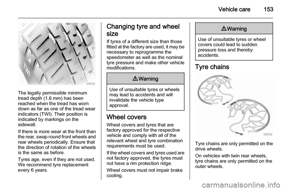
The legally permissible minimum
tread depth (1.6 mm) has been
reached when the tread has worn
down as far as one of the tread wear
indicators (TWI). Their position is
indicated by markings on the
sidewall.
If there is more wear at the front than
the rear, swap round front wheels and rear wheels periodically. Ensure that
the direction of rotation of the wheels
is the same as before.
Tyres age, even if they are not used.
We recommend tyre replacement
every 6 years.
Changing tyre and wheel
size If tyres of a different size than those
fitted at the factory are used, it may be necessary to reprogramme the
speedometer as well as the nominal
tyre pressure and make other vehicle
modifications.9 Warning
Use of unsuitable tyres or wheels
may lead to accidents and will
invalidate the vehicle type
approval.
Wheel covers
Wheel covers and tyres that are
factory approved for the respective
vehicle and comply with all of the
relevant wheel and tyre combination requirements must be used.
If the wheel covers and tyres used are
not factory approved, the tyres must
not have a rim protection ridge.
Wheel covers must not impair brake
cooling.
9 Warning
Use of unsuitable tyres or wheel
covers could lead to sudden
pressure loss and thereby
accidents.
Tyre chains
Tyre chains are only permitted on the
drive wheels.
On vehicles with twin rear wheels,
tyre chains are only permitted on the
outer wheels.
Page 157 of 201
Vehicle care155
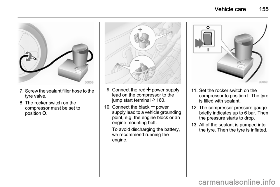
7.Screw the sealant filler hose to the
tyre valve.
8. The rocker switch on the compressor must be set to
position O.9.
Connect the red < power supply
lead on the compressor to the
jump start terminal 3 160.
10. Connect the black ] power
supply lead to a vehicle grounding
point, e.g. the engine block or an
engine mounting bolt.
To avoid discharging the battery,
we recommend running the
engine.11. Set the rocker switch on the compressor to position I. The tyre
is filled with sealant.
12. The compressor pressure gauge briefly indicates up to 6 bar. Then
the pressure starts to drop.
13. All of the sealant is pumped into the tyre. Then the tyre is inflated.
Page 158 of 201
156Vehicle care
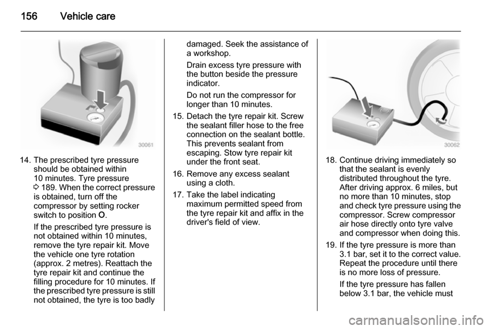
14. The prescribed tyre pressureshould be obtained within
10 minutes. Tyre pressure
3 189 . When the correct pressure
is obtained, turn off the
compressor by setting rocker
switch to position O.
If the prescribed tyre pressure is
not obtained within 10 minutes,
remove the tyre repair kit. Move
the vehicle one tyre rotation
(approx. 2 metres). Reattach the
tyre repair kit and continue the
filling procedure for 10 minutes. If
the prescribed tyre pressure is still not obtained, the tyre is too badly
damaged. Seek the assistance of
a workshop.
Drain excess tyre pressure with
the button beside the pressure
indicator.
Do not run the compressor for
longer than 10 minutes.
15. Detach the tyre repair kit. Screw the sealant filler hose to the free
connection on the sealant bottle.
This prevents sealant from
escaping. Stow tyre repair kit
under the front seat.
16. Remove any excess sealant using a cloth.
17. Take the label indicating maximum permitted speed from
the tyre repair kit and affix in the
driver's field of view.
18. Continue driving immediately so that the sealant is evenly
distributed throughout the tyre.
After driving approx. 6 miles, but
no more than 10 minutes, stop
and check tyre pressure using the
compressor. Screw compressor
air hose directly onto tyre valve
and compressor when doing this.
19. If the tyre pressure is more than 3.1 bar , set it to the correct value.
Repeat the procedure until there
is no more loss of pressure.
If the tyre pressure has fallen
below 3.1 bar, the vehicle must
Page 159 of 201

Vehicle care157
not be driven. Seek theassistance of a workshop.
20. Stow tyre repair kit under the front
seat.
Notice
The driving characteristics of the repaired tyre are severely affected, therefore have this tyre replaced.
If unusual noise is heard or the
compressor becomes hot, turn
compressor off for at least
30 minutes.
The built-in safety valve opens at a
pressure of 7 bar (102 psi).
Note the expiry date of the kit. After
this date its sealing capability is no
longer guaranteed. Pay attention to
storage information on sealant
bottle.
Replace the used sealant bottle. Dispose of the bottle as prescribed
by applicable laws.
The compressor and sealant can be used from approx. -30 °C.
The adapters supplied can be used
to pump up other items e.g.
footballs, air mattresses, inflatabledinghies etc. They are located on the underside of the compressor. To
remove, screw on compressor air hose and withdraw adapter.
Wheel changing Some vehicles are equipped with a
tyre repair kit instead of a spare wheel 3 154.
Make the following preparations and
observe the following information:
■ Park the vehicle on a level, firm and
non-slippery surface. The frontwheels must be in the straight-ahead position.
■ Apply the parking brake and engage first gear or reverse gear.
■ Switch off the air suspension system 3 110.
■ Remove the spare wheel 3 159.
■ Never change more than one wheel
at a time.
■ Use the jack only to change wheels
in case of puncture, not for
seasonal winter or summer tyre
change.■ If the ground on which the vehicle is standing is soft, a solid board
(max. 1 cm thick) should be placed
under the jack.
■ No people or animals may be in the
vehicle when it is jacked-up.
■ Never crawl under a jacked-up vehicle.
■ Do not start the engine when the vehicle is raised on the jack.
■ Clean wheel bolts/nuts and their threads before mounting the wheel.9 Warning
Do not grease wheel bolt, wheel
nut and wheel nut cone.
1. Remove the wheel cover using the hook supplied. Vehicle tools
3 150.
2. Install the wheel wrench ensuring that it locates securely and loosen
each wheel bolt/nut by half a turn.