turn signal VAUXHALL MOVANO_B 2015.5 Owner's Manual
[x] Cancel search | Manufacturer: VAUXHALL, Model Year: 2015.5, Model line: MOVANO_B, Model: VAUXHALL MOVANO_B 2015.5Pages: 215, PDF Size: 5.11 MB
Page 13 of 215

In brief11
1Fixed air vents .................... 107
2 Headlight range
adjustment ........................... 90
Ultrasonic parking assist .....130
Traction control system ......124
Electronic stability program 125
3 Side air vents .....................106
4 Light switch .......................... 89
Turn and lane-change
signals .................................. 91
High beam and low beam,
headlight flash ......................90
Sidelights .............................. 89
Automatic light control .......... 89
Exit lighting ........................... 95
Front fog lights .....................92
Rear fog light ........................ 92
5 Instruments .......................... 74
Transmission display ............77
Driver Information Centre ...... 846 Horn ..................................... 70
Driver airbag ........................ 50
7 Remote control on
steering wheel .......................69
Cruise control .....................126
8 Windscreen wiper,
windscreen washer system ..70
Trip computer ........................ 86
9 Coin tray ............................... 61
10 Power outlet ......................... 72
11 Centre air vents .................. 106
12 Storage compartment ...........61
13 Front passenger airbag .........50
Storage compartment ..........61
14 Glovebox .............................. 62
15 Cupholders ........................... 62
16 Climate control system ......... 96
17 Cigarette lighter .................... 73
Power outlet ......................... 7218Gear lever, Manual
transmission ........................ 117
Manual transmission
automated ........................... 118
19 Cruise control and speed
limiter ................................. 126
Manual transmission
automated,
Winter and Laden modes ....120
Idle speed control ...............111
Stop-start system ................111
20 Ignition switch with
steering wheel lock ............110
21 Steering column controls .....70
22 Steering wheel adjustment ..69
23 Bonnet release lever ..........140
24 Auxiliary heater ...................102
25 Storage compartment ..........61
Fuse box ............................ 157
Page 15 of 215
In brief13
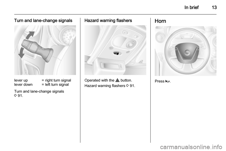
Turn and lane-change signalslever up=right turn signallever down=left turn signal
Turn and lane-change signals
3 91.
Hazard warning flashers
Operated with the ¨ button.
Hazard warning flashers 3 91.
Horn
Press j.
Page 32 of 215
30Keys, doors and windows
AlarmWhen triggered, the alarm sounds via a separate battery-backed power
sounder, and the hazard warning
lights flash simultaneously. The
number and duration of alarm signals
are stipulated by legislation.
If the vehicle battery is disconnected
or its power supply is interrupted, the
alarm siren will be triggered. First
deactivate the anti-theft alarm system if the vehicle battery must be
disconnected.
To silence the alarm siren (if
triggered) and therefore deactivate
the anti-theft alarm system, reconnect
vehicle battery and unlock vehicle
with remote control button c (or
switch on the ignition).
Immobiliser The system is part of the ignition
switch and checks whether the
vehicle is allowed to be started with
the key being used.The immobiliser is activated
automatically after the key has been removed from the ignition switch and
also if the key is left in the ignition
switch when the engine is turned off.
If the engine cannot be started, switch off the ignition and remove key, wait
approx. 2 seconds and then repeat
the start attempt.If start attempt is
unsuccessful, attempt to start the
engine using the spare key and seek
the assistance of a workshop.
Notice
The immobiliser does not lock the doors. You should always lock the
vehicle after leaving it and switch on
the anti-theft alarm system 3 20,
3 28.Exterior mirrors
Convex shape
The convex exterior mirror contains
an aspherical area and reduces blind spots. The shape of the mirror makes objects appear smaller, which will
affect the ability to estimate
distances.
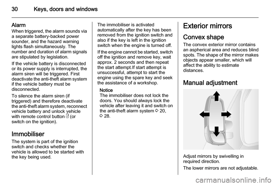
Manual adjustment
Adjust mirrors by swivelling in
required direction.
The lower mirrors are not adjustable.
Page 81 of 215
Instruments and controls79
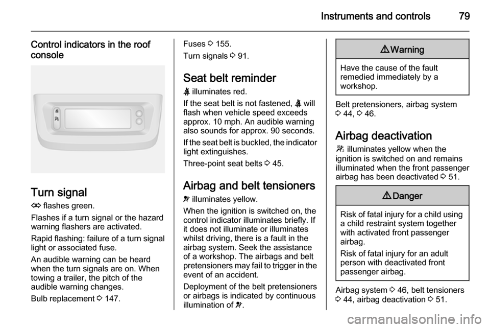
Control indicators in the roof
console
Turn signal
O flashes green.
Flashes if a turn signal or the hazard
warning flashers are activated.
Rapid flashing: failure of a turn signal
light or associated fuse.
An audible warning can be heard
when the turn signals are on. When
towing a trailer, the pitch of the
audible warning changes.
Bulb replacement 3 147.
Fuses 3 155.
Turn signals 3 91.
Seat belt reminder X illuminates red.
If the seat belt is not fastened, X will
flash when vehicle speed exceeds
approx. 10 mph. An audible warning
also sounds for approx. 90 seconds.
If the seat belt is buckled, the indicator
light extinguishes.
Three-point seat belts 3 45.
Airbag and belt tensioners
v illuminates yellow.
When the ignition is switched on, the
control indicator illuminates briefly. If
it does not illuminate or illuminates
whilst driving, there is a fault in the
airbag system. Seek the assistance
of a workshop. The airbags and belt
pretensioners may fail to trigger in the
event of an accident.
Deployment of the belt pretensioners
or airbags is indicated by continuous
illumination of v.9
Warning
Have the cause of the fault
remedied immediately by a
workshop.
Belt pretensioners, airbag system
3 44, 3 46.
Airbag deactivation
W illuminates yellow when the
ignition is switched on and remains
illuminated when the front passenger
airbag has been deactivated 3 51.
9 Danger
Risk of fatal injury for a child using
a child restraint system together
with activated front passenger
airbag.
Risk of fatal injury for an adult
person with deactivated front
passenger airbag.
Airbag system 3 46, belt tensioners
3 44, airbag deactivation 3 51.
Page 93 of 215
Lighting91
If the vehicle is equipped with theautomatic light control function, the
system switches between daytime
running lights and headlights
automatically depending on the
lighting conditions. Automatic light
control 3 89.
Adaptive forward lighting Cornering light
Depending on the steering angle,
vehicle speed and gear selected
when cornering, an additional light
will illuminate the corner of the road
on the respective side.
The cornering light is switched off
automatically after prolonged use and at vehicle speeds above 25 mph.Hazard warning flashers
Operated with the ¨ button.
In the event of hard braking, the
hazard warning flashers may turn on
automatically. Switch off by pressing
the ¨ button.
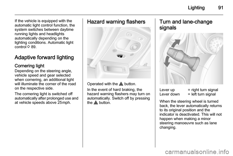
Turn and lane-change
signalsLever up=right turn signalLever down=left turn signal
When the steering wheel is turned
back, the lever automatically returns
to its original position and the
indicator is deactivated. This will not happen when making a minor
steering manoeuvre such as lane
changing.
Page 97 of 215
Lighting95Lighting featuresExit lighting
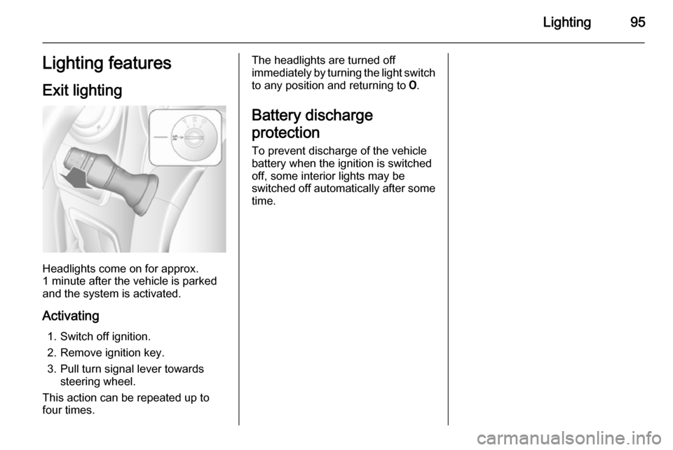
Headlights come on for approx.
1 minute after the vehicle is parked
and the system is activated.
Activating 1. Switch off ignition.
2. Remove ignition key.
3. Pull turn signal lever towards steering wheel.
This action can be repeated up to
four times.
The headlights are turned off
immediately by turning the light switch
to any position and returning to 7.
Battery discharge
protection To prevent discharge of the vehiclebattery when the ignition is switched off, some interior lights may be
switched off automatically after some
time.
Page 105 of 215
Climate control103
Before starting or programming the
system to start, turn the vehicle's
climate control system to heat and the
air distribution to V.
Switch off when not required. Heating stops automatically after the
programmed runtime. It will also
cease to operate if the vehicle fuel
level drops too low.
During operation, power from the
vehicle battery is used. The driving
time should therefore be at least as
long as the heating time. For short
journey times, check the vehicle
battery regularly and recharge if
necessary.
To ensure efficient performance,
briefly operate the auxiliary heater
once a month.
Control units
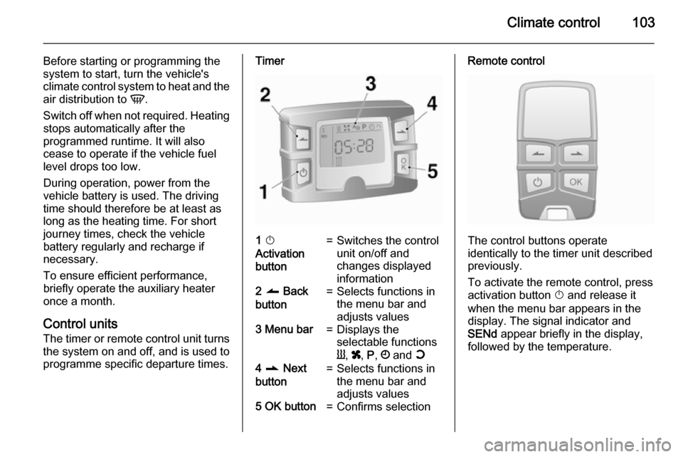
The timer or remote control unit turns the system on and off, and is used to
programme specific departure times.Timer1 X
Activation
button=Switches the control
unit on/off and
changes displayed
information2 q Back
button=Selects functions in
the menu bar and
adjusts values3 Menu bar=Displays the
selectable functions
Y , x , P , Ö and Y4 r Next
button=Selects functions in
the menu bar and
adjusts values5 OK button=Confirms selectionRemote control
The control buttons operate
identically to the timer unit described
previously.
To activate the remote control, press activation button X and release it
when the menu bar appears in the display. The signal indicator and
SENd appear briefly in the display,
followed by the temperature.
Page 137 of 215

Driving and operating135
If the trailer starts snaking, drive moreslowly, do not attempt to correct the
steering and brake sharply if
necessary.
When driving downhill, drive in the
same gear as if driving uphill and
drive at a similar speed.
Adjust tyre pressure to the value
specified for full load 3 201.
Trailer towing Trailer loads
The permissible trailer loads are
vehicle-dependent and engine-
dependent maximum values which
must not be exceeded. The actual
trailer load is the difference between
the actual gross weight of the trailer
and the actual coupling socket load
with the trailer coupled.
The permissible trailer loads are
specified in the vehicle documents. In general, they are valid for gradients
up to max. 12 %.
The permitted trailer load applies up to the specified incline and up to an
altitude of 1000 metres above sealevel. Since engine power decreases as altitude increases due to the airbecoming thinner, therefore reducing
climbing ability, the permissible gross
train weight also decreases by 10 % for every 1000 metres of additional
altitude. The gross train weight does
not have to be reduced when driving on roads with slight inclines (less than 8 %, e.g. motorways).
The permissible gross train weight
must not be exceeded. This weight is
specified on the identification plate
3 182.
Vertical coupling load
The vertical coupling load is the load
exerted by the trailer on the coupling
ball. It can be varied by changing the
weight distribution when loading the
trailer.
The maximum permissible vertical
coupling load is specified on the
towing equipment identification plate
and in the vehicle documents. Always aim for the maximum load, especially
in the case of heavy trailers. The
vertical coupling load should never
fall below 25 kg.In the case of trailer loads of
1200 kg or more, the vertical coupling load should not be less than 50 kg.
Rear axle load When the trailer is coupled and the
towing vehicle fully loaded (including
all occupants), the permissible rear
axle load (see identification plate or
vehicle documents) must not be
exceeded.
Towing equipmentCaution
When operating without a trailer,
remove the coupling ball bar.
Towing equipment audible
warning For vehicles fitted with towing
equipment, when connected to a
trailer the pitch of the audible warning
changes upon operation of the turn
signals.
Page 138 of 215
136Driving and operating
The pitch of the audible warning will
change if a turn signal light on the
trailer or the towing vehicle fails.
Trailer stability assist
If the system detects snaking
movements, engine power is reduced
and the vehicle/trailer combination is
selectively braked until the snaking ceases. While the system is working,keep steering wheel as still as
possible.
Trailer stability assist (TSA) is a
function of the Electronic stability
program (ESP) 3 125.Auxiliary features
Power take-off
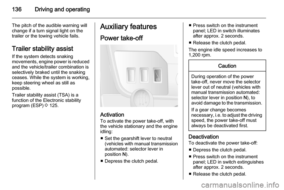
Activation
To activate the power take-off, with
the vehicle stationary and the engine
idling:
■ Set the gearshift lever to neutral (vehicles with manual transmissionautomated: selector lever in
position N).
■ Depress the clutch pedal.
■ Press switch on the instrument panel; LED in switch illuminatesafter approx. 2 seconds.
■ Release the clutch pedal.
The engine idle speed increases to
1,200 rpm.Caution
During operation of the power
take-off, never move the selector
lever out of neutral (vehicles with
manual transmission automated:
selector lever in position N), to
avoid damage to the transmission.
If a gear change becomes
necessary, i.e. to adjust the driving
speed, the power take-off must always be deactivated first.
Deactivation
To deactivate the power take-off:
■ Depress the clutch pedal.
■ Press switch on the instrument panel; LED in switch extinguishes
after approx. 2 seconds.
■ Release the clutch pedal.
Page 152 of 215
150Vehicle careAdaptive forward lightingCornering light
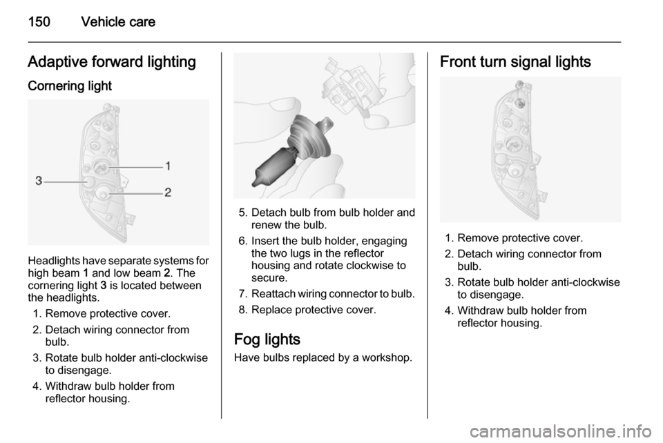
Headlights have separate systems forhigh beam 1 and low beam 2. The
cornering light 3 is located between
the headlights.
1. Remove protective cover.
2. Detach wiring connector from bulb.
3. Rotate bulb holder anti-clockwise to disengage.
4. Withdraw bulb holder from reflector housing.
5. Detach bulb from bulb holder andrenew the bulb.
6. Insert the bulb holder, engaging the two lugs in the reflectorhousing and rotate clockwise to
secure.
7. Reattach wiring connector to bulb.
8. Replace protective cover.
Fog lights
Have bulbs replaced by a workshop.
Front turn signal lights
1. Remove protective cover.
2. Detach wiring connector from bulb.
3. Rotate bulb holder anti-clockwise to disengage.
4. Withdraw bulb holder from reflector housing.