suspension VAUXHALL MOVANO_B 2018 Owner's Manual
[x] Cancel search | Manufacturer: VAUXHALL, Model Year: 2018, Model line: MOVANO_B, Model: VAUXHALL MOVANO_B 2018Pages: 261, PDF Size: 6.3 MB
Page 46 of 261
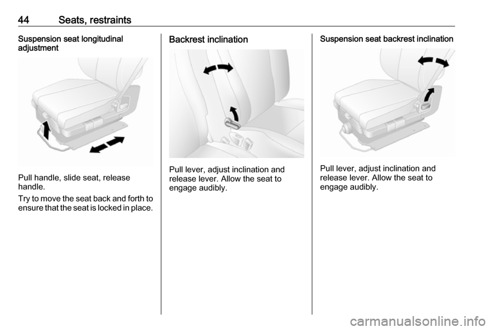
44Seats, restraintsSuspension seat longitudinal
adjustment
Pull handle, slide seat, release
handle.
Try to move the seat back and forth to ensure that the seat is locked in place.
Backrest inclination
Pull lever, adjust inclination and
release lever. Allow the seat to
engage audibly.
Suspension seat backrest inclination
Pull lever, adjust inclination and
release lever. Allow the seat to
engage audibly.
Page 47 of 261
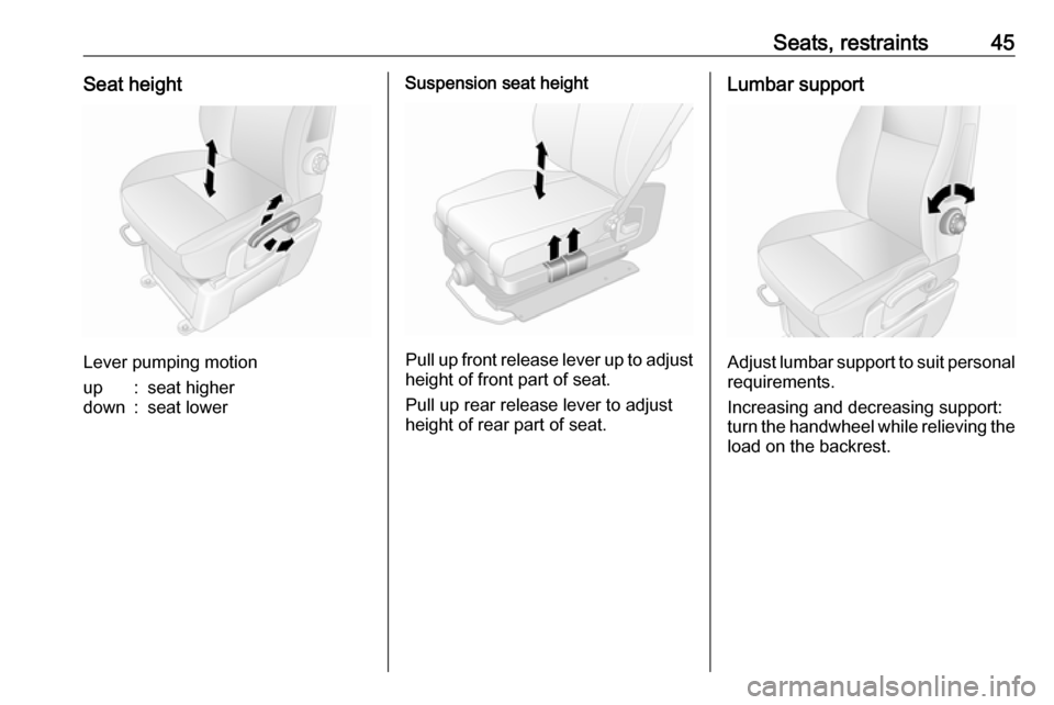
Seats, restraints45Seat height
Lever pumping motion
up:seat higherdown:seat lowerSuspension seat height
Pull up front release lever up to adjustheight of front part of seat.
Pull up rear release lever to adjust height of rear part of seat.
Lumbar support
Adjust lumbar support to suit personal requirements.
Increasing and decreasing support:
turn the handwheel while relieving the load on the backrest.
Page 48 of 261
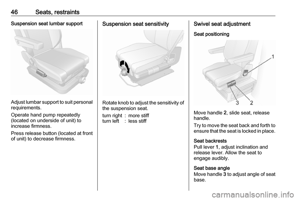
46Seats, restraintsSuspension seat lumbar support
Adjust lumbar support to suit personalrequirements.
Operate hand pump repeatedly
(located on underside of unit) to
increase firmness.
Press release button (located at front
of unit) to decrease firmness.
Suspension seat sensitivity
Rotate knob to adjust the sensitivity of the suspension seat.
turn right:more stiffturn left:less stiffSwivel seat adjustment
Seat positioning
Move handle 2, slide seat, release
handle.
Try to move the seat back and forth to ensure that the seat is locked in place.
Seat backrests
Pull lever 1, adjust inclination and
release lever. Allow the seat to
engage audibly.
Seat base angle
Move handle 3 to adjust angle of seat
base.
Page 50 of 261
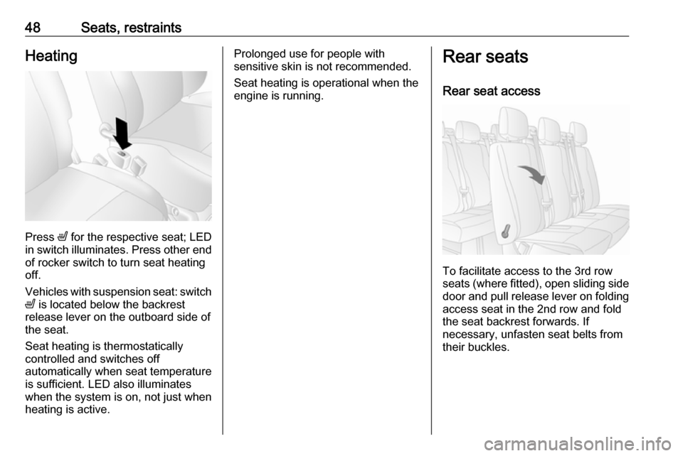
48Seats, restraintsHeating
Press ß for the respective seat; LED
in switch illuminates. Press other end of rocker switch to turn seat heating
off.
Vehicles with suspension seat: switch ß is located below the backrest
release lever on the outboard side of
the seat.
Seat heating is thermostatically
controlled and switches off
automatically when seat temperature
is sufficient. LED also illuminates
when the system is on, not just when
heating is active.
Prolonged use for people with
sensitive skin is not recommended.
Seat heating is operational when the
engine is running.Rear seats
Rear seat access
To facilitate access to the 3rd row
seats (where fitted), open sliding side door and pull release lever on foldingaccess seat in the 2nd row and fold
the seat backrest forwards. If
necessary, unfasten seat belts from
their buckles.
Page 133 of 261

Driving and operating131Driving and
operatingDriving hints ............................... 132
Driving economically ...............132
Control of the vehicle ...............132
Steering ................................... 132
Starting and operating ...............133
New vehicle running-in ............133
Ignition switch positions ...........133
Starting the engine ..................134
Idle speed control ....................135
Overrun cut-off ........................ 135
Stop-start system ....................135
Parking .................................... 138
Air suspension ......................... 139
Engine exhaust .......................... 141
Diesel particle filter ..................141
Catalytic converter ...................141
AdBlue ..................................... 142
Manual transmission ..................149
Manual transmission automa‐ ted .............................................. 149
Transmission display ...............149
Starting the engine ..................150
Selector lever .......................... 150Manual mode........................... 151
Electronic driving programmes 151
Fault ........................................ 152
Interruption of power supply ....153
Brakes ........................................ 153
Antilock brake system .............153
Parking brake .......................... 154
Brake assist ............................. 155
Hill start assist ......................... 155
Ride control systems .................155
Traction Control system ..........155
Electronic stability program .....156
Limited-slip rear axle ...............158
Driver assistance systems .........158
Cruise control .......................... 158
Speed limiter ........................... 162
Parking assist .......................... 162
Rear view camera ...................164
Lane departure warning ..........166
Fuel ............................................ 167
Fuel for diesel engines ............167
Refuelling ................................ 168
Fuel consumption - CO 2-
Emissions .............................. 169
Trailer hitch ................................ 170
General information .................170
Driving characteristics and towing tips .............................. 170
Trailer towing ........................... 170Towing equipment ...................171
Trailer stability assist ...............171
Auxiliary features .......................171
Power take-off ......................... 171
Page 141 of 261
Driving and operating139● Close the windows.
● Turn the ignition key to position
0 and remove it. Turn the
steering wheel until the
steering wheel lock is felt to
engage.
Lock the vehicle 3 22 and activate the
anti-theft locking system 3 32 and
anti-theft alarm system 3 32.
Air suspension
Operates automatically when the
vehicle is driven. The air suspension
system constantly adjusts the ride
height according to the vehicle load.
Caution
To ensure safe operation of the air
suspension system, do not exceed the maximum permissible gross
vehicle weight rating. Refer to
identification plate 3 223 or the
vehicle documents.
For further information on the air
suspension system, refer to the
operating instructions supplied.
Master switchCaution
The air suspension system must
be switched off when the vehicle is being towed, jump‐started, raised
off the ground or transported.
Do not switch off the air
suspension system when driving.
Jump starting 3 212, Towing the
vehicle 3 214.
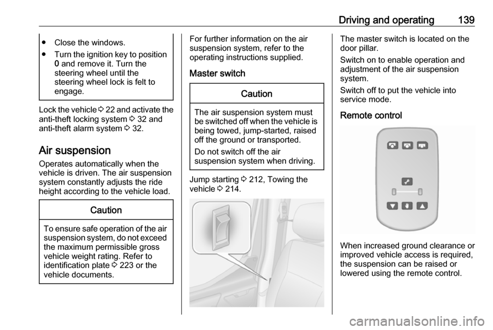
The master switch is located on the
door pillar.
Switch on to enable operation and
adjustment of the air suspension
system.
Switch off to put the vehicle into
service mode.
Remote control
When increased ground clearance or improved vehicle access is required,the suspension can be raised or
lowered using the remote control.
Page 142 of 261
140Driving and operatingCaution
Ensure there is adequate
clearance and that there are no
obstructions when adjusting the
suspension height.
The remote control unit is magnetic
and may be fixed to any metal part of the vehicle or stored in its holder.
With the engine running, press the appropriate button for two seconds to
adjust the suspension height.
Indicator light will flash intermittently
while height adjustment is in progress
and illuminates when complete.
If the ignition is switched on with
engine not running, the suspension
height can only be lowered.
Notice
Handle with care, protect from
moisture and high temperatures and
avoid unnecessary operation.
Pre-programmed settings
Adjusts the suspension height to one
of three pre-programmed positions.
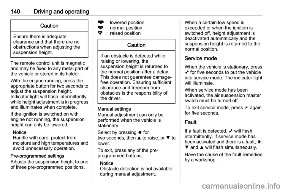
l:lowered positionk:normal positionj:raised positionCaution
If an obstacle is detected while
raising or lowering, the
suspension height is returned to the normal position after a delay.
This does not guarantee damage- free operation. Ensuring sufficient
clearance and freedom from
obstacles is the responsibility of the driver.
Manual settings
Manual adjustment can only be
performed when the vehicle is
stationary.
Select by pressing h for
two seconds , then R to raise, or S to
lower.
To exit, press any of the pre-
programmed buttons.
Notice
Obstacle detection is not available
during manual adjustment.
When a certain low speed is
exceeded or when the ignition is
switched off, height adjustment is deactivated automatically and the
suspension height is returned to the
normal position.
Service modeWhen the vehicle is stationary, press
i for five seconds to put the vehicle
into service mode. The indicator light
will illuminate.
When service mode has been
activated, the air suspension master
switch must be turned off.
To exit service mode, press i again
for five seconds.
Fault
If a fault is detected, i will flash
intermittently. If service mode has been activated and there is a fault, h,
S and R will flash simultaneously.
Have the cause of the fault remedied
by a workshop.
Page 197 of 261
Vehicle care195SymbolCircuitKWindscreen wipernHeating and ventilation
system / Air conditioningVHeated windscreenQPneumatic suspension
Instrument panel fuse box
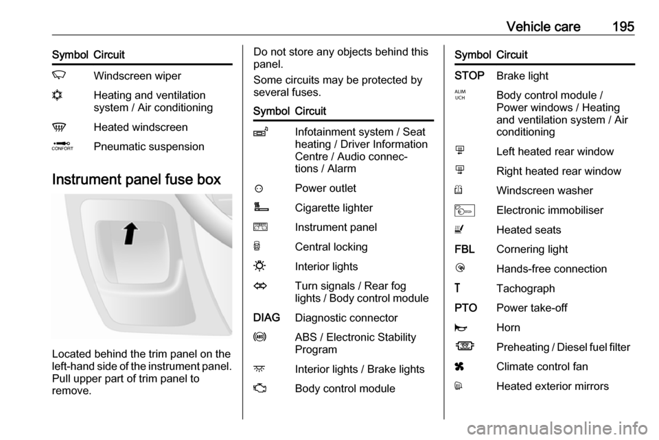
Located behind the trim panel on the
left-hand side of the instrument panel. Pull upper part of trim panel to
remove.
Do not store any objects behind this
panel.
Some circuits may be protected by
several fuses.SymbolCircuitZInfotainment system / Seat
heating / Driver Information
Centre / Audio connec‐
tions / Alarm?Power outletÌCigarette lightereInstrument panelUCentral locking0Interior lightsOTurn signals / Rear fog
lights / Body control moduleDIAGDiagnostic connectoruABS / Electronic Stability
ProgramdInterior lights / Brake lightsZBody control moduleSymbolCircuitSTOPBrake lightIBody control module /
Power windows / Heating
and ventilation system / Air
conditioningmLeft heated rear windownRight heated rear windowRWindscreen washerMElectronic immobiliserUHeated seatsFBLCornering lightlHands-free connection&TachographPTOPower take-offjHornÍPreheating / Diesel fuel filterxClimate control fandHeated exterior mirrors
Page 209 of 261

Vehicle care207not be driven. Seek the
assistance of a workshop.
21. Stow tyre repair kit under the front
seat.
Notice
The driving characteristics of the repaired tyre are severely affected,therefore have this tyre replaced.
If unusual noise is heard or the
compressor becomes hot, turn
compressor off for at least
30 minutes.
The built-in safety valve opens at a
pressure of seven bar (102 psi).
Note the expiry date of the kit. After
this date its sealing capability is no
longer guaranteed. Pay attention to
storage information on sealant
bottle.
Replace the used sealant bottle. Dispose of the bottle as prescribed
by applicable laws.
The compressor and sealant can be used from approx. -30 °C.Wheel changing
Some vehicles are equipped with a
tyre repair kit instead of a spare wheel
3 204.
Make the following preparations and
observe the following information:
● Park the vehicle on a level, firm and non-slippery surface. The
front wheels must be in the
straight-ahead position.
● Apply the parking brake and engage first gear or reverse gear
(manual transmission) or N
(manual transmission
automated).
● Switch off the air suspension system 3 139.
● Remove the spare wheel 3 209.
● Never change more than one wheel at a time.
● Use the jack only to change wheels in case of puncture, not
for seasonal winter or summer
tyre change.
● The jack is maintenance-free.● If the ground on which the vehicle
is standing is soft, a solid board
(max. 1 cm thick) should be
placed under the jack.
● No people or animals may be in the vehicle when it is jacked-up.
● Never crawl under a jacked-up vehicle.
● Do not start the engine when the vehicle is raised on the jack.
● Clean wheel bolts/nuts and their threads before mounting the
wheel.9 Warning
Do not grease wheel bolt, wheel
nut and wheel nut cone.
1. Remove the wheel cover using the hook supplied. Vehicle tools
3 198.
Depending on vehicle, first
remove the bolt/nut covers by
hand then remove the wheel
cover, or press wheel cover at the points indicated by the arrows and
turn to release.
Page 214 of 261
212Vehicle care● Do not drive faster than 50 mph.● Drive particularly carefully on wet
and snow-covered road
surfaces.Jump starting
The jump start terminal is located in
the engine compartment.
A vehicle with a discharged vehicle
battery can be started using jump
leads and the vehicle battery of
another vehicle.
Do not start with a quick charger.9 Warning
Be extremely careful when starting
with jump leads. Any deviation
from the following instructions can
lead to injuries or damage caused
by battery explosion or damage to the electrical systems of both
vehicles.
9 Warning
Avoid contact of the battery with
eyes, skin, fabrics and painted
surfaces. The fluid contains
sulphuric acid which can cause
injuries and damage in the event
of direct contact.
Caution
The air suspension system must
be switched off prior to jump
starting.
Air suspension 3 139.
● Never expose the vehicle battery
to naked flames or sparks.
● A discharged vehicle battery can already freeze at a temperature
of 0 °C. Defrost the frozen vehicle
battery before connecting jump leads.
● Wear eye protection and protective clothing when
handling a vehicle battery.
● Use a booster battery with the same voltage (12 volts). Its
capacity (Ah) must not be much
less than that of the discharged
vehicle battery.
● Use jump leads with insulated terminals and a cross section of
at least 25 mm 2
.
● Do not disconnect the discharged
battery from the vehicle.