sensor VAUXHALL MOVANO_B 2020 User Guide
[x] Cancel search | Manufacturer: VAUXHALL, Model Year: 2020, Model line: MOVANO_B, Model: VAUXHALL MOVANO_B 2020Pages: 351, PDF Size: 9.32 MB
Page 229 of 351
Driving and operating227Idle speed control
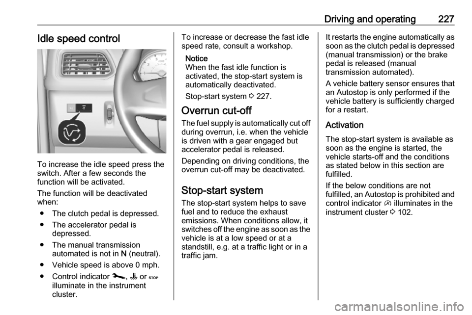
To increase the idle speed press the
switch. After a few seconds the
function will be activated.
The function will be deactivated
when:
● The clutch pedal is depressed.
● The accelerator pedal is depressed.
● The manual transmission automated is not in N (neutral).
● Vehicle speed is above 0 mph. ● Control indicator j, W or C
illuminate in the instrument
cluster.
To increase or decrease the fast idle
speed rate, consult a workshop.
Notice
When the fast idle function is
activated, the stop-start system is
automatically deactivated.
Stop-start system 3 227.
Overrun cut-off
The fuel supply is automatically cut off
during overrun, i.e. when the vehicle
is driven with a gear engaged but accelerator pedal is released.
Depending on driving conditions, the
overrun cut-off may be deactivated.
Stop-start system The stop-start system helps to save
fuel and to reduce the exhaust
emissions. When conditions allow, it
switches off the engine as soon as the
vehicle is at a low speed or at a
standstill, e.g. at a traffic light or in a
traffic jam.It restarts the engine automatically as
soon as the clutch pedal is depressed (manual transmission) or the brake
pedal is released (manual
transmission automated).
A vehicle battery sensor ensures that
an Autostop is only performed if the vehicle battery is sufficiently charged
for a restart.
Activation
The stop-start system is available as
soon as the engine is started, the
vehicle starts-off and the conditions
as stated below in this section are
fulfilled.
If the below conditions are not
fulfilled, an Autostop is prohibited and
control indicator \ illuminates in the
instrument cluster 3 102.
Page 254 of 351
252Driving and operatingDeactivation of the functionality
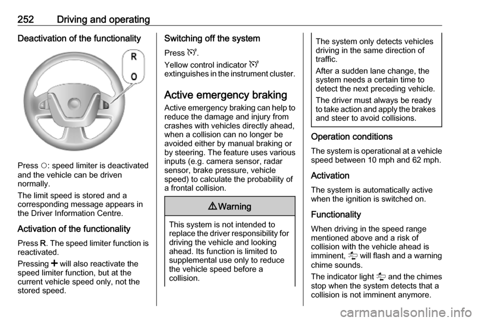
Press $: speed limiter is deactivated
and the vehicle can be driven
normally.
The limit speed is stored and a
corresponding message appears in
the Driver Information Centre.
Activation of the functionality Press R. The speed limiter function is
reactivated.
Pressing < will also reactivate the
speed limiter function, but at the
current vehicle speed only, not the
stored speed.
Switching off the system
Press U.
Yellow control indicator U
extinguishes in the instrument cluster.
Active emergency braking Active emergency braking can help toreduce the damage and injury from
crashes with vehicles directly ahead,
when a collision can no longer be
avoided either by manual braking or
by steering. The feature uses various
inputs (e.g. camera sensor, radar
sensor, brake pressure, vehicle
speed) to calculate the probability of
a frontal collision.9 Warning
This system is not intended to
replace the driver responsibility for driving the vehicle and looking
ahead. Its function is limited to
supplemental use only to reduce
the vehicle speed before a
collision.
The system only detects vehicles
driving in the same direction of
traffic.
After a sudden lane change, the
system needs a certain time to
detect the next preceding vehicle.
The driver must always be ready
to take action and apply the brakes and steer to avoid collisions.
Operation conditions
The system is operational at a vehicle
speed between 10 mph and 62 mph.
Activation
The system is automatically active
when the ignition is switched on.
Functionality
When driving in the speed range
mentioned above and a risk of
collision with the vehicle ahead is
imminent, l will flash and a warning
chime sounds.
The indicator light l and the chimes
stop when the system detects that a
collision is not imminent anymore.
Page 256 of 351
254Driving and operatingpedal to override the automatic
braking if the situation and the
surroundings permit.
In the following cases, active
emergency braking performance is limited:
● driving on winding or hilly roads
● detecting all vehicles, especially vehicles with a trailer, tractors,
muddy vehicles, etc.
● detecting a vehicle when weather
limits visibility, such as in fog,
rain, or snow
● driving during nighttime
● sensor in the windscreen or radar
unit behind the front bumper blocked by snow, ice, slush, mud, dirt, etc.
● windscreen damaged or affected
by foreign objects, e.g. stickers
Complete attention is always required
while driving, and you should be
ready to take action and apply the
brakes and / or steer the vehicle to
avoid crashes.Fault
In case the system requires a service, a message is displayed in the Driver
Information Centre.
Additionally, warning lights l and
j illuminate at the same time.
When the system detects that its
function is not available, warning light
l or j illuminates and stays on.
Additionally, a message in the Driver
Information Centre appears. The system may be temporarily disrupted
(for example: radar or camera
obscured by dirt, mud, snow etc.). In
this case, park the vehicle and switch off the engine. Clean the windscreen
area around the camera and the
detection zone of the radar in the front bumper. When the warning lights and
messages still appear after starting
the vehicle again, seek the
assistance of a workshop.Parking assist9 Warning
It is the driver who bears full
responsibility for the parking
manoeuvre.
Always check the surrounding
area while reversing and using the rear parking assist system.
The parking assist measures the
distance between the vehicle and
obstacles behind and, if available, in
front of the vehicle. It informs and
warns the driver by giving acoustic
signals.
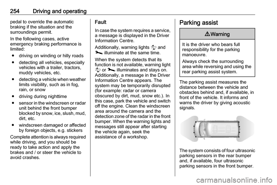
The system consists of four ultrasonic parking sensors in the rear bumper
and, if available, four ultrasonic
parking sensors in the front bumper.
Page 257 of 351
Driving and operating255The ultrasonic parking sensors can
be activated or deactivated in the
settings menu in the Info Display.
Notice
Attached parts in the detection area
cause system malfunction.
Activation
The rear parking assist is activated
when reverse gear is engaged. The
front-rear parking assist is activated
when a gear is engaged. Readiness
for operation is indicated by a brief
acoustic signal.
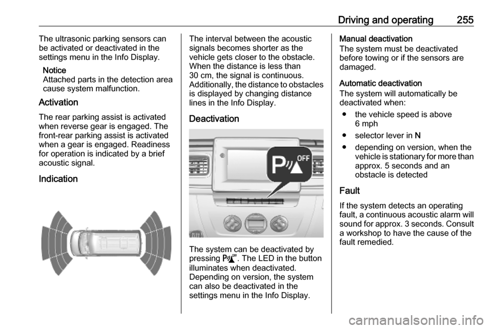
IndicationThe interval between the acoustic
signals becomes shorter as the
vehicle gets closer to the obstacle.
When the distance is less than
30 cm, the signal is continuous.
Additionally, the distance to obstacles is displayed by changing distance
lines in the Info Display.
Deactivation
The system can be deactivated by
pressing =. The LED in the button
illuminates when deactivated.
Depending on version, the system
can also be deactivated in the
settings menu in the Info Display.
Manual deactivation
The system must be deactivated
before towing or if the sensors are
damaged.
Automatic deactivation
The system will automatically be
deactivated when:
● the vehicle speed is above 6 mph
● selector lever in N
● depending on version, when the vehicle is stationary for more than
approx. 5 seconds and an
obstacle is detected
Fault
If the system detects an operating
fault, a continuous acoustic alarm will sound for approx. 3 seconds. Consult
a workshop to have the cause of the
fault remedied.
Page 258 of 351
256Driving and operatingCaution
When reversing, the area should
be free from obstacles which could impact on the underside of the
vehicle.
Impact to the rear axle, which may
not be visible, could lead to
uncharacteristic changes in the
vehicle handling. In the event of
such an impact, consult a
workshop.
Basic notes on parking assist
system
9 Warning
Under certain circumstances,
various reflective surfaces on
objects or clothing as well as
external noise sources may cause the system to fail to detect
obstacles.
Special attention must be paid to
low obstacles which can damage
the lower part of the bumper.
Caution
Performance of the sensors can
be reduced when sensors are
covered, e.g. by ice or snow.
Performance of the parking assist
system can be reduced due to
heavy loading.
Special conditions apply if there
are taller vehicles involved (e.g.
off-road vehicles, mini vans,
vans). Object identification in the
upper part of these vehicles
cannot be guaranteed.
Objects with a very small reflection
cross-section, e.g. objects of
narrow size or soft materials, may
not be detected by the system.
The parking assist system will not
detect objects which are out of the detection range of the sensors.
Side blind spot alert
The side blind spot alert system
detects and reports objects on either
side of the vehicle, within a specified
blind spot zone. The system displays
a visual alert in each exterior mirror,
when detecting objects that may not
be visible in the interior and exterior
mirrors.
Side blind spot alert uses some of the
parking assist sensors which are
located in the front and rear bumper
on both sides of the vehicle.9 Warning
Side blind spot alert does not
replace driver vision.
The system does not detect:
● vehicles outside the side blind zones which may be rapidly
approaching
● pedestrians, cyclists or animals
Before changing a lane, always
check all mirrors, look over the
shoulder and use the turn signal.
Activation
The system is activated when the
speed of the vehicle is between
approx. 19 mph and 87 mph.
Page 259 of 351
Driving and operating257Deactivation
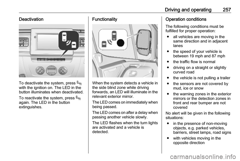
To deactivate the system, press .
with the ignition on. The LED in the
button illuminates when deactivated.
To reactivate the system, press .
again. The LED in the button
extinguishes.
Functionality
When the system detects a vehicle in the side blind zone while driving
forwards, an LED will illuminate in the
relevant exterior mirror.
The LED comes on immediately when being passed.
The LED comes on after a delay when
passing another vehicle slowly.
The LED flashes when the turn lights
are activated and a vehicle is
detected.
Operation conditions
The following conditions must be
fulfilled for proper operation:
● all vehicles are moving in the same direction and in adjacent
lanes
● the speed of your vehicle is between 19 mph and 87 mph
● the traffic flow is normal
● driving on a straight or slightly curved road
● the vehicle is not pulling a trailer ● the sensors are not covered by mud, ice or snow
● the warning zones in the exterior mirrors or the detection zones in
front and rear bumper are not
covered
No alert will be given in the following
situations:
● in the presence of non-moving objects, e.g. parked vehicles,
barriers, street lamps, road signs
● with vehicles moving in the opposite direction
Page 293 of 351
Vehicle care291The tyre pressure data refers to cold
tyres. It applies to summer and winter
tyres.
Always inflate the spare tyre to the
highest pressure specified for this
tyre size.
Incorrect tyre pressures will impair
safety, vehicle handling, comfort and fuel economy and will increase tyre
wear.
Tyre pressures differ depending on
various options. For the correct tyre pressure value, follow the procedure
below:
1. Identify the type of drive.
2. Identify the gross vehicle weight.
3. Identify the respective tyre.
The tyre pressure tables show all
possible tyre combinations 3 315.
For the tyres approved for your
vehicle, refer to the EEC Certificate of Conformity provided with your vehicle
or other national registration
documents.
The driver is responsible for correct
adjustment of tyre pressure.9 Warning
If the pressure is too low, this can
result in considerable tyre warm-
up and internal damage, leading to tread separation and even to tyre
blow-out at high speeds.
9 Warning
For specific tyres the
recommended tyre pressure as
shown in the tyre pressure table may exceed the maximum tyre
pressure as indicated on the tyre.
Never exceed the maximum tyre
pressure as indicated on the tyre.
Temperature dependency
Tyre pressure depends on the
temperature of the tyre. During
driving, tyre temperature and
pressure increase.
Tyre pressure values provided on the
tyre information label and tyre
pressure chart are valid for cold tyres, which means at 20 °C. The pressure
increases by nearly 1.5 psi (10 kPa /
0.1 bar) for a 10 °C temperature
increase. This must be considered
when warm tyres are checked.
Trailer towing
When towing a trailer with a fully laden vehicle, the tyre pressure must
be increased by 20 kPa / 0.2 bar
(3.0 psi) and the maximum speed
limited to 60 mph.
Trailer towing 3 264.
Rear-wheel drive, with twin rear
wheels
When inflating the outer tyre, the
inflation tube should be passed
between the two wheels.
Tyre pressure monitoringsystem
The tyre pressure monitoring system
uses radio and sensor technology to
check tyre pressure levels.
Page 294 of 351
292Vehicle careCaution
Tyre pressure monitoring system
warns only about low tyre pressure condition and does not replace
regular tyre maintenance by the
driver.
All wheels must be equipped with pressure sensors and the tyres must
have the prescribed pressure.
Notice
In countries where the tyre pressure
monitoring system is legally
required, the use of wheels without
pressure sensors will invalidate the
vehicle operating permit.
The tyre pressure monitoring system
sensors monitor the tyre pressure
and transmit tyre pressure readings
to a receiver located in the vehicle.
Tyre pressure chart 3 315.
Low tyre pressure condition
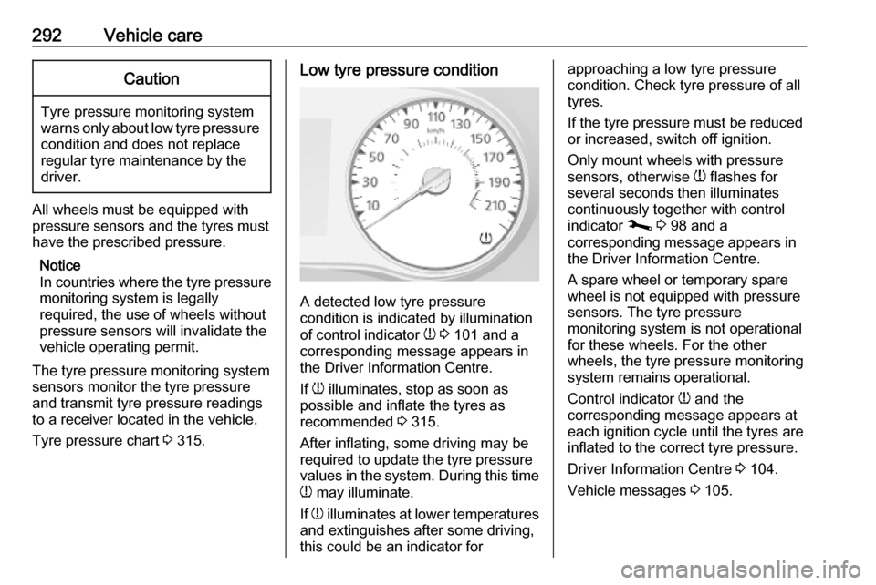
A detected low tyre pressure
condition is indicated by illumination
of control indicator w 3 101 and a
corresponding message appears in
the Driver Information Centre.
If w illuminates, stop as soon as
possible and inflate the tyres as
recommended 3 315.
After inflating, some driving may be
required to update the tyre pressure
values in the system. During this time
w may illuminate.
If w illuminates at lower temperatures
and extinguishes after some driving,
this could be an indicator for
approaching a low tyre pressure
condition. Check tyre pressure of all
tyres.
If the tyre pressure must be reduced
or increased, switch off ignition.
Only mount wheels with pressure
sensors, otherwise w flashes for
several seconds then illuminates
continuously together with control
indicator j 3 98 and a
corresponding message appears in
the Driver Information Centre.
A spare wheel or temporary spare
wheel is not equipped with pressure
sensors. The tyre pressure
monitoring system is not operational
for these wheels. For the other
wheels, the tyre pressure monitoring
system remains operational.
Control indicator w and the
corresponding message appears at
each ignition cycle until the tyres are
inflated to the correct tyre pressure.
Driver Information Centre 3 104.
Vehicle messages 3 105.
Page 295 of 351
Vehicle care293PunctureA puncture or severely under-inflated
tyre is indicated by illumination of
control indicator w together with C
3 99 and a corresponding message
appears in the Driver Information
Centre. Stop vehicle and switch off
engine.
Tyre pressure 3 315.
Tyre repair kit 3 295.
Spare wheel 3 300.
Wheel changing 3 298.
Relearn functionAfter a puncture has been repaired
and the driver has inflated the tyres to
the correct tyre pressure, the tyre
pressure monitoring system needs to recalculate.
Tyre pressure 3 315.
Tyre repair kit 3 295.
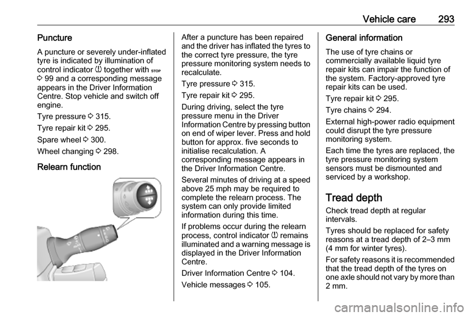
During driving, select the tyre
pressure menu in the Driver
Information Centre by pressing button
on end of wiper lever. Press and hold button for approx. five seconds to
initialise recalculation. A
corresponding message appears in
the Driver Information Centre.
Several minutes of driving at a speed above 25 mph may be required to
complete the relearn process. The system can only provide limited
information during this time.
If problems occur during the relearn
process, control indicator w remains
illuminated and a warning message is displayed in the Driver Information
Centre.
Driver Information Centre 3 104.
Vehicle messages 3 105.General information
The use of tyre chains or
commercially available liquid tyre
repair kits can impair the function of
the system. Factory-approved tyre
repair kits can be used.
Tyre repair kit 3 295.
Tyre chains 3 294.
External high-power radio equipment
could disrupt the tyre pressure
monitoring system.
Each time the tyres are replaced, the
tyre pressure monitoring system
sensors must be dismounted and
serviced by a workshop.
Tread depth Check tread depth at regular
intervals.
Tyres should be replaced for safety
reasons at a tread depth of 2–3 mm
(4 mm for winter tyres).
For safety reasons it is recommended
that the tread depth of the tyres on
one axle should not vary by more than 2 mm.
Page 320 of 351

318Customer informationOhmstrasse 4, 85716
Unterschleissheim, Germany
Operation frequency: 125 kHz
Maximum output:
42 dBμA/m @ 10 m
Infotainment system NAVI 80
IntelliLink
TomTom Int’l BV
De Ruijterkade 154, 1011 AC
Amsterdam, The Netherlands
Operation frequency:
2400 - 2483.5 MHz
Maximum output: 100 mW EIRP
Infotainment system NAVI 50
IntelliLink
LG Electronics
LG Electronics European Shared
Service Center B.V., Krijgsman 1,
1186 DM Amstelveen, The
Netherlands
Operation frequency: 2.4 GHz
Maximum output: 100 mW EIRP
Infotainment system Radio 15
Visteon Electronics04 Rue Nelson Mandela, Zone
Industrielle Borj Cedria, 2055 Bir El
Bey, Tunisia
Operation frequency:
2400 – 2483,5 MHz
Maximum output: 100 mW EIRP
Parking heater remote control
receiver
Eberspaecher Climate Control
Systems GmbH & Co. KG
Eberspaecherstrasse 24, 73730
Esslingen, Germany
Operation frequency: N/A
Maximum output: N/A
Parking heater remote control
transmitter
Eberspaecher Climate Control
Systems GmbH & Co. KG
Eberspaecherstrasse 24, 73730
Esslingen, Germany
Operation frequency: 434,6 MHz
Maximum output: 10dBm
Telematics control unit
Continental Automotive1 Rue de Clairefontaine, 78120
Rambouillet, France
Operation frequency:
2400 – 2483,5 MHz
Maximum output: 100 mW EIRP
Telematics display
MASTERNAUT INTERNATIONAL
4 rue Charles Cros 27400 Louviers,
FranceOperation
frequency (MHz)Maximum output
(dBm)900 MHz33 dBm1800 MHz30 dBm
Tyre pressure monitoring receiver
Schrader Electronics
Trooperslane Industrial Estate, 2
Meadowbank Rd, Carrickfergus
BT38 8YF, United Kingdom
Operation frequency: N/A
Maximum output: N/A
Tyre pressure sensors
Schrader Electronics