brake light VAUXHALL VIVA 2016.5 User Guide
[x] Cancel search | Manufacturer: VAUXHALL, Model Year: 2016.5, Model line: VIVA, Model: VAUXHALL VIVA 2016.5Pages: 197, PDF Size: 5.27 MB
Page 115 of 197

Driving and operating113Manual mode
To utilise the engine braking effect, select a lower gear in good time when
driving downhill. Changing into
manual mode is only possible while the engine is running.
Rocking the vehicle Rocking the vehicle is only
permissible if the vehicle is stuck in
sand, mud or snow. Move the selector
lever between R and D in a repeat
pattern. Do not race the engine and
avoid sudden acceleration.
Parking
The most recently engaged gear (see transmission display) remains
engaged when switching off ignition. With N, no gear is engaged.
Therefore always apply the parking
brake when switching off ignition. If
parking brake is not applied, P flashes
in the transmission display and the
key cannot be removed from the
ignition switch. P stops flashing in the
transmission display as soon as the
parking brake is slightly applied.When the ignition is switched off, the
transmission no longer responds to
movement of the selector lever.
Tyre pressure monitoring system
To start the sensor matching process of the tyre pressure monitoring
system, the selector lever must be
moved and held in position N for
five seconds. P illuminates in the
transmission display to indicate that
the sensor matching process can be
started.
Tyre pressure monitoring system
3 151.
Manual mode If a higher gear is selected when the
engine speed is too low, or a lower
gear when the speed is too high, the
shift is not executed. This prevents
the engine from running at too low or too high an engine speed. M and the
number of the selected gear will be
flashed, then the current gear is
displayed again..If engine speed is too low, the
transmission automatically shifts to a
lower gear.
When + or - is selected in automatic
mode, the transmission switches to
manual mode and shifts accordingly.
Gear shift indication
The symbol R with a number
alongside it, is indicated when
gearshifting is recommended for fuel saving reasons.
Shift indication appears only in
manual mode.
Electronic driving programmes
The adaptive programme tailors
gearshifting to the driving conditions, e.g. greater load or gradients.
Fault
To prevent damage to the manual
transmission automated, the clutch is engaged automatically at high clutch
temperatures.
Page 116 of 197

114Driving and operatingIn the event of a fault, control indicatorg illuminates. Additionally, a
warning message is displayed in the
Driver Information Centre. Vehicle
messages 3 79.
Continued driving is restricted or not
possible, depending on the fault.
Have the cause of the fault remedied
by a workshop.Brakes
The brake system comprises two
independent brake circuits.
If a brake circuit fails, the vehicle can
still be braked using the other brake
circuit. However, braking effect is
achieved only when the brake pedal
is depressed firmly. Considerably
more force is needed for this. The braking distance is extended. Seek
the assistance of a workshop before
continuing the journey.
When the engine is not running, the
support of the brake servo unit
disappears once the brake pedal has been depressed once or twice.
Braking effect is not reduced, but
braking requires significantly greater
force. It is especially important to bear this in mind when being towed.
Control indicator R 3 69.
Antilock brake system
Antilock brake system (ABS)
prevents the wheels from locking.ABS starts to regulate brake pressure as soon as a wheel shows a tendency to lock. The vehicle remains
steerable, even during hard braking.
ABS control is made apparent
through a pulse in the brake pedal
and the noise of the regulation
process.
For optimum braking, keep the brake
pedal fully depressed throughout the
braking process, despite the fact that
the pedal is pulsating. Do not reduce
the pressure on the pedal.
After starting-off the system performs
a self-test which may be audible.
Control indicator u 3 70.
Adaptive brake light
During full braking, all three brake
lights flash for the duration of ABS
control.
Page 117 of 197
Driving and operating115Fault9Warning
If there is a fault in the ABS, the
wheels may be liable to lock due
to braking that is heavier than
normal. The advantages of ABS are no longer available. During
hard braking, the vehicle can no longer be steered and may
swerve.
Have the cause of the fault remedied
by a workshop.
Parking brake
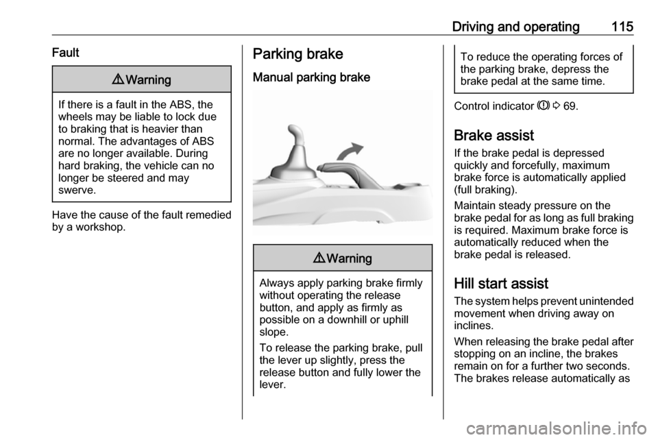
Manual parking brake9 Warning
Always apply parking brake firmly
without operating the release
button, and apply as firmly as
possible on a downhill or uphill
slope.
To release the parking brake, pull
the lever up slightly, press the
release button and fully lower the
lever.
To reduce the operating forces of
the parking brake, depress the
brake pedal at the same time.
Control indicator R 3 69.
Brake assist
If the brake pedal is depressed
quickly and forcefully, maximum
brake force is automatically applied
(full braking).
Maintain steady pressure on the
brake pedal for as long as full braking is required. Maximum brake force is
automatically reduced when the
brake pedal is released.
Hill start assist
The system helps prevent unintended movement when driving away on
inclines.
When releasing the brake pedal after
stopping on an incline, the brakes
remain on for a further two seconds.
The brakes release automatically as
Page 133 of 197
Vehicle care131Vehicle careGeneral Information...................131
Accessories and vehicle modifications .......................... 131
Vehicle storage ........................132
End-of-life vehicle recovery .....132
Vehicle checks ........................... 133
Performing work ......................133
Bonnet ..................................... 133
Engine oil ................................. 134
Engine coolant ......................... 135
Washer fluid ............................ 135
Brakes ..................................... 136
Brake fluid ............................... 136
Vehicle battery ......................... 136
Wiper blade replacement ........138
Bulb replacement .......................138
Halogen headlights ..................139
Fog lights ................................. 140
Front turn signal lights .............141
Tail lights ................................. 141
Side turn signal lights ..............142
Centre high-mounted brake light ......................................... 143
Number plate light ...................143Interior lights ............................ 144
Instrument panel illumination ...144
Electrical system ........................144
Fuses ....................................... 144
Engine compartment fuse box . 146
Instrument panel fuse box .......147
Vehicle tools .............................. 149
Tools ........................................ 149
Wheels and tyres .......................150
Winter tyres ............................. 150
Tyre designations ....................150
Tyre pressure .......................... 150
Tyre pressure monitoring
system .................................... 151
Tread depth ............................. 155
Changing tyre and wheel size . 155 Wheel covers ........................... 155
Tyre chains .............................. 156
Tyre repair kit .......................... 156
Wheel changing .......................159
Spare wheel ............................ 161
Jump starting ............................. 163
Towing ....................................... 165
Towing the vehicle ...................165
Appearance care .......................166
Exterior care ............................ 166
Interior care ............................. 168General Information
Accessories and vehiclemodifications
We recommend the use of genuine
parts and accessories and factory approved parts specific for your
vehicle type. We cannot assess or
guarantee reliability of other products
- even if they have a regulatory or
otherwise granted approval.
Do not make any modifications to the
electrical system, e.g. changes of
electronic control units (chip tuning).Caution
When transporting the vehicle on
a train or on a recovery vehicle, the
mud flaps might be damaged.
Page 143 of 197

Vehicle care141
2. Disconnect the electricalconnector from the bulb holder.
3. Remove the bulb assembly anticlockwise and pull it straight
out.
4. Insert a new bulb assembly straight into the lamp and rotate
clockwise.
5. Reconnect the electrical connector.
Front turn signal lights
1. Rotate the bulb holderanticlockwise and remove.
2. Rotate bulb anticlockwise and remove from bulb holder.
3. Replace bulb.
4. Insert the bulb holder into the reflector and rotate clockwise.
Tail lightsTail lights, turn signal lights, brake
lights and reversing lights
1. Unscrew both screws.
2. Remove tail light assembly. Take care that the cable duct remains in
position.
Page 144 of 197

142Vehicle care
3. tail light / brake light 1
turn signal light 2
tail light 3
reversing light (passenger side) /
rear fog light (driver's side) 4.4. Rotate bulb holder anticlockwise.
5. Remove bulb holder. Push bulb
into socket slightly, rotate anti-
clockwise, remove and renew
bulb.
6. Insert bulb holder into the tail light
assembly and screw into place.
Connect wiring plug. Install tail
light assembly in body and tighten screws. Close covers and
engage.
7. Switch on ignition, operate and check all lights.
Side turn signal lights
To replace bulb, remove lamp
housing:
1. Slide lamp to the front and remove
it out of the front wing with the rear
end.
Page 145 of 197

Vehicle care143
2. Turn bulb holder anticlockwiseand remove from housing.
3. Pull bulb from bulb holder andreplace it.
4. Insert bulb holder and turnclockwise.
5. Insert front end into front wing, slide forward and insert rear end.
Centre high-mounted brake light
Have LEDs replaced by a workshop.
Number plate light
1. Unscrew both screws.
2. Remove bulb housing downwards, taking care not to pull
on the cable.
Rotate bulb holder anticlockwise
to disengage.
3. Remove bulb from bulb holder and replace it.
4. Insert bulb holder into bulb housing and turn clockwise.
5. Insert bulb housing and secure using a screwdriver.
Page 149 of 197
Vehicle care147No.Circuit18Engine control module219Injection system/Ignition20Air conditioning system21Battery sensor22Electric steering column lock23Cooling fan low24–25Exterior mirror switch26Engine control module/Manual
transmission automated
module27Fuel system28Brake switch29Seat occupancy recognition30Headlight range adjustment31Horn32Front fog light33High beam leftNo.Circuit34High beam right35–36Rear wiper37Cornering light left38Washer system39Cornering light right40–41–42Starter 243Instrument panel44Manual transmission auto‐
mated45Starter 146ABS47Cooling fan high48Front wiper49Body control module/Retained
power offAfter having changed defective fuses
close the fuse box cover and press
until it engages.
If the fuse box cover is not closed
correctly, malfunction may occur.
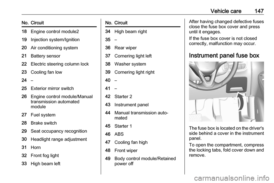
Instrument panel fuse box
The fuse box is located on the driver's
side behind a cover in the instrument
panel.
To open the compartment, compress
the locking tabs, fold cover down and remove.
Page 156 of 197
154Vehicle careTyre pressure sensor matching
process
Each tyre pressure sensor has a
unique identification code. The
identification code must be matched
to a new tyre/wheel position after
rotating the tyres or exchanging the
complete wheel set and if one or more
tyre pressure sensors were replaced. The tyre pressure sensor matching
process should also be performed
after replacing a spare tyre with a
road tyre containing the tyre pressure sensor.
The malfunction light w and the
warning message or code should go
off at the next ignition cycle. The
sensors are matched to the wheel
positions, using a relearn tool, in the
following order: left side front wheel,
right side front wheel, right side rear
wheel and left side rear wheel. The
turn signal light at the current active
position is illuminated until sensor is
matched.
Consult a workshop for service or
purchase a relearn tool. There are
two minutes to match the first wheel
position, and five minutes overall tomatch all four wheel positions. If it
takes longer, the matching process stops and must be restarted.
The tyre pressure sensor matching
process is:
1. Apply the parking brake.
2. Turn the ignition on.
3. On vehicles with manual transmission automated: Press
and hold brake pedal. Move and
hold the selector lever for five
seconds in position N until P is
displayed in the Driver Information Centre. P indicates
that the sensor matching process can be started.
On vehicles with manual
transmission: select neutral.
4. Use MENU on the turn signal
lever to select the Vehicle
Information Menu in the Driver
Information Centre.
5. Turn the adjuster wheel to scroll to
the tyre pressure menu.6. Press SET/CLR to begin the
sensor matching process. A
message requesting acceptance
of the process should be
displayed.
7. Press SET/CLR again to confirm
the selection. The horn sounds
twice to indicate that the receiver
is in relearn mode.
8. Start with the left side front wheel.
9. Place the relearn tool against the tyre sidewall, near the valve stem.Then press the button to activate
the tyre pressure sensor. A horn
chirp confirms that the sensor
identification code has been
matched to this wheel position.
10. Proceed to the right side front wheel, and repeat the procedure
in Step 9.
11. Proceed to the right side rear wheel, and repeat the procedure
in Step 9.
12. Proceed to the left side rear wheel, and repeat the procedure
in Step 9. The horn sounds twice
to indicate that the sensor
identification code has been
Page 167 of 197

Vehicle care1654. Switch on electrical consumers(e.g. headlights, heated rear
window) of the vehicle receiving
the jump start.
5. Reverse above sequence exactly when removing leads.Towing
Towing the vehicle The towing eye is stowed with the
vehicle tools 3 149.
1. Disengage cap by using the
screwdriver and remove the cap.
2. Screw in the towing eye as far as it will go until it stops in a
horizontal position.
3. Attach a tow rope – or better still a
tow rod – to the towing eye.
General
The towing eye must only be used for
towing and not for recovering the
vehicle.
Switch on ignition to release steering
wheel lock and to permit operation of
brake lights, horn and windscreen
wiper.
Transmission in neutral.