instrument cluster VAUXHALL VIVA 2017 Owner's Manual
[x] Cancel search | Manufacturer: VAUXHALL, Model Year: 2017, Model line: VIVA, Model: VAUXHALL VIVA 2017Pages: 201, PDF Size: 5.29 MB
Page 60 of 201

58Instruments and controlsInstruments and
controlsControls ....................................... 59
Steering wheel adjustment ........59
Steering wheel controls .............59
Heated steering wheel ...............59
Horn ........................................... 60
Windscreen wiper/washer .........60
Rear window wiper/washer .......61
Outside temperature ..................61
Clock ......................................... 61
Power outlets ............................. 63
Cigarette lighter ......................... 63
Ashtrays .................................... 63
Warning lights, gauges and indi‐ cators ........................................... 63
Instrument cluster ......................63
Speedometer ............................. 63
Odometer .................................. 64
Trip odometer ............................ 64
Tachometer ............................... 64
Fuel gauge ................................ 64
Fuel selector .............................. 65
Engine coolant temperature gauge ....................................... 66
Service display .......................... 66Control indicators ......................67
Turn signal ................................. 69
Seat belt reminder .....................70
Airbag and belt tensioners .........70
Airbag deactivation ....................70
Charging system .......................71
Malfunction indicator light ..........71
Service vehicle soon .................71
Brake and clutch system ...........71
Operate pedal ............................ 71
Antilock brake system (ABS) .....72
Gear shifting .............................. 72
Power steering .......................... 72
Lane departure warning ............72
Ultrasonic parking assist ...........72
Electronic Stability Control off ...72
Electronic Stability Control and Traction Control system ...........72
Traction Control system off .......73
Engine coolant temperature ......73
Tyre pressure monitoring system ...................................... 73
Engine oil pressure ....................73
Low fuel ..................................... 74
Immobiliser ................................ 74
Reduced engine power .............74
Exterior light .............................. 74
High beam ................................. 74
Fog light ..................................... 74
Rear fog light ............................. 74Cruise control............................ 74
Speed limiter ............................. 74
Bonnet open .............................. 74
Door open .................................. 75
Information displays .....................75
Driver Information Centre ..........75
Info display ................................ 80
Vehicle messages ........................81
Warning chimes .........................83
Battery voltage .......................... 83
Vehicle personalisation ................84
Telematics service .......................86
OnStar ....................................... 86
Page 65 of 201
Instruments and controls63Power outlets
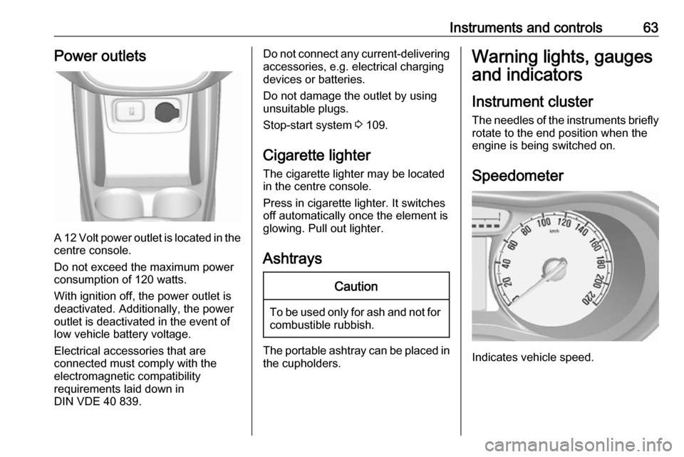
A 12 Volt power outlet is located in the
centre console.
Do not exceed the maximum power
consumption of 120 watts.
With ignition off, the power outlet is
deactivated. Additionally, the power outlet is deactivated in the event of
low vehicle battery voltage.
Electrical accessories that are
connected must comply with the
electromagnetic compatibility
requirements laid down in
DIN VDE 40 839.
Do not connect any current-delivering accessories, e.g. electrical charging
devices or batteries.
Do not damage the outlet by using
unsuitable plugs.
Stop-start system 3 109.
Cigarette lighter The cigarette lighter may be located
in the centre console.
Press in cigarette lighter. It switches
off automatically once the element is
glowing. Pull out lighter.
AshtraysCaution
To be used only for ash and not for combustible rubbish.
The portable ashtray can be placed inthe cupholders.
Warning lights, gauges
and indicators
Instrument cluster
The needles of the instruments briefly
rotate to the end position when the
engine is being switched on.
Speedometer
Indicates vehicle speed.
Page 70 of 201

68Instruments and controlsControl indicators in the instrument cluster
Page 77 of 201
Instruments and controls75Door openN illuminates.
A door or the tailgate is open.Information displays
Driver Information Centre
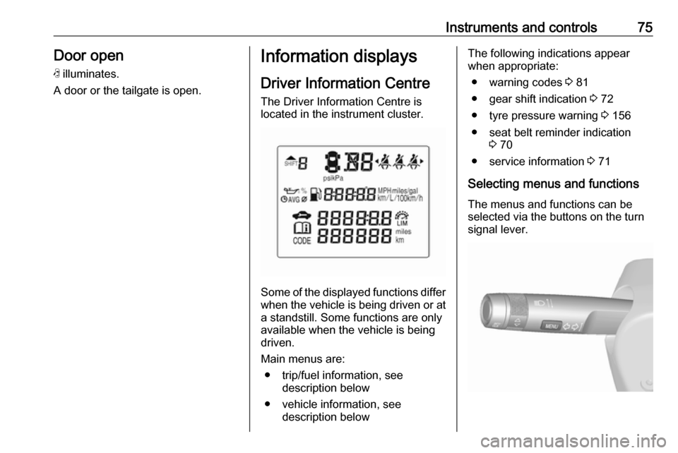
The Driver Information Centre is
located in the instrument cluster.
Some of the displayed functions differ
when the vehicle is being driven or at a standstill. Some functions are only
available when the vehicle is being
driven.
Main menus are: ● trip/fuel information, see description below
● vehicle information, see description below
The following indications appear
when appropriate:
● warning codes 3 81
● gear shift indication 3 72
● tyre pressure warning 3 156
● seat belt reminder indication 3 70
● service information 3 71
Selecting menus and functions The menus and functions can be
selected via the buttons on the turn
signal lever.
Page 82 of 201
80Instruments and controlsTyre load
The tyre pressure category accordingto the actual tyre inflation pressure
can be selected 3 156.
Outside temperature
Display of current outside
temperature.
Language
Select preferred country language as
display language.
Time
Display of current time.
Info display
The Info-Display is located in the
instrument panel near the instrument
cluster.
Depending on the vehicle
configuration the vehicle has a
● Graphic-Info-Display
or
● 7'' Colour-Info-Display with
touch-screen functionality
The vehicle has a 7'' Colour-Info-
Display with touch-screen
functionality.
The Info displays can indicate: ● time 3 61
● outside temperature 3 61
● date 3 61
● Infotainment system, see description in the Infotainment
manual
● indication of parking assist instructions 3 125
● system messages
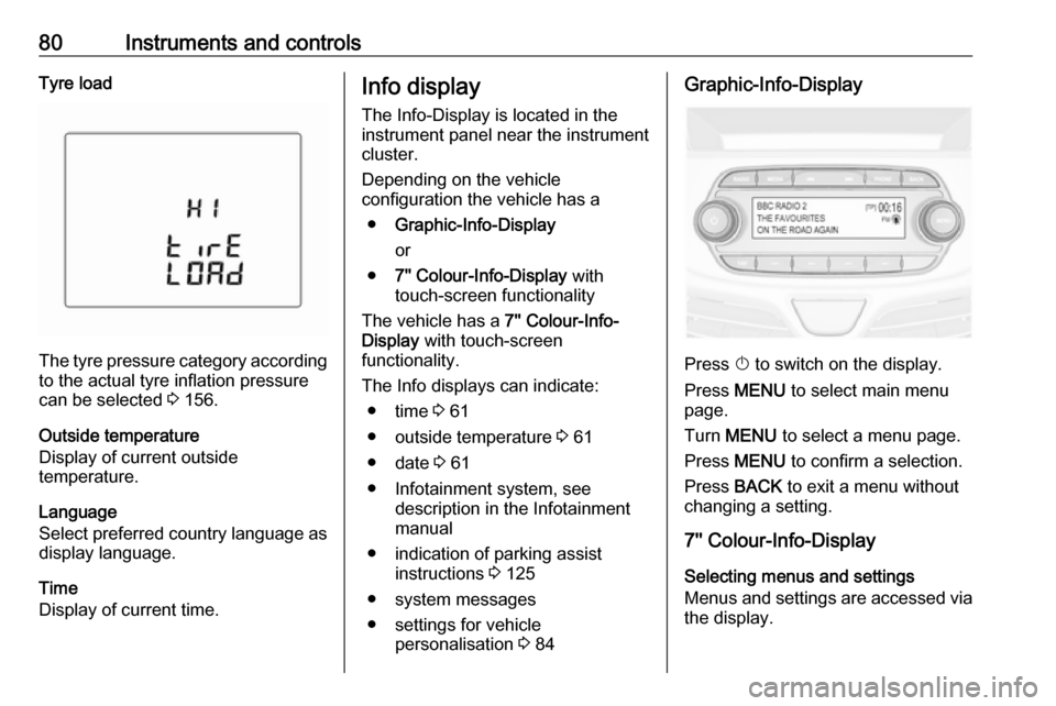
● settings for vehicle personalisation 3 84Graphic-Info-Display
Press X to switch on the display.
Press MENU to select main menu
page.
Turn MENU to select a menu page.
Press MENU to confirm a selection.
Press BACK to exit a menu without
changing a setting.
7'' Colour-Info-Display
Selecting menus and settings
Menus and settings are accessed via
the display.
Page 125 of 201

Driving and operating123Press m; control indicator m in
instrument cluster illuminates white.
Activation
Accelerate to the desired speed and
turn thumb wheel to SET/-, the
current speed is stored and
maintained. Control indicator m in
instrument cluster illuminates green. Set speed is indicated on the display. Accelerator pedal can be released.
Vehicle speed can be increased by depressing the accelerator pedal.
When the accelerator pedal is
released, the previously stored speed
is resumed.
Cruise control remains activated
while gearshifting.
Increase speed With cruise control active, hold thumb
wheel turned to RES/+ or briefly turn
to RES/+ repeatedly: speed
increases continuously or in small
increments.
Alternatively accelerate to the desired speed and store by turning to SET/-.Reduce speed
With cruise control active, hold thumb
wheel turned to SET/- or briefly turn to
SET/- repeatedly: speed decreases
continuously or in small increments.
Deactivation
Press y; control indicator m in
instrument cluster illuminates white.
Cruise control is deactivated. Last
stored speed remains in memory for
later speed resume.
Automatic deactivation: ● Vehicle speed is below approx. 15 mph.
● The brake pedal is depressed.
● The clutch pedal is depressed for
a few seconds.
● The selector lever is in N.
● Engine speed is in a very low range.
● The Traction Control system or Electronic Stability Control is
operating.Resume stored speed
Turn thumb wheel to RES/+ at a
speed above 15 mph. The stored
speed will be obtained.
Switching off
Press m, control indicator m in
instrument cluster extinguishes. The
stored speed is deleted.
Pressing L to activate the speed
limiter or switching off the ignition also
switches off cruise control and
deletes the stored speed.
Speed limiter
The speed limiter prevents exceeding a preset maximum speed.
The maximum speed can be set at
speeds above 18 mph.
The driver can only accelerate up to
the preset speed. Deviations from the
limited speed may occur when driving
downhill.
The preset speed limit is displayed in
the Driver Information Centre when
the system is active.
Page 127 of 201
Driving and operating125By switching off the ignition, speed
limiter is also deactivated, but the
speed limit will be stored for next
speed limiter activation.
Parking assist
Rear parking assist9 Warning
It is the driver who bears full
responsibility for the parking
manoeuvre.
Always check the surrounding
area while reversing and using the rear parking assist system.
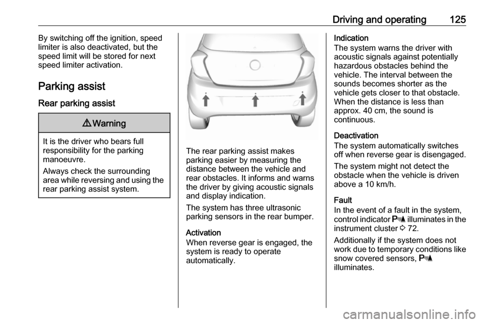
The rear parking assist makes
parking easier by measuring the
distance between the vehicle and
rear obstacles. It informs and warns
the driver by giving acoustic signals
and display indication.
The system has three ultrasonic
parking sensors in the rear bumper.
Activation
When reverse gear is engaged, the
system is ready to operate
automatically.
Indication
The system warns the driver with
acoustic signals against potentially
hazardous obstacles behind the
vehicle. The interval between the
sounds becomes shorter as the
vehicle gets closer to that obstacle.
When the distance is less than
approx. 40 cm, the sound is
continuous.
Deactivation
The system automatically switches
off when reverse gear is disengaged.
The system might not detect the
obstacle when the vehicle is driven above a 10 km/h.
Fault
In the event of a fault in the system,
control indicator r illuminates in the
instrument cluster 3 72.
Additionally if the system does not work due to temporary conditions like
snow covered sensors, r
illuminates.
Page 128 of 201
126Driving and operatingBasic notes on parking assist
systems9 Warning
Under certain circumstances,
various reflective surfaces on
objects or clothing as well as
external noise sources may cause the system to fail to detect
obstacles.
Special attention must be paid to
low obstacles which can damage
the lower part of the bumper.
Caution
Performance of the system can be reduced when sensors are
covered, e.g. by ice or snow.
Performance of the parking assist
system can be reduced due to
heavy loading.
Special conditions apply if there
are taller vehicles in the vicinity
(e.g. off-road vehicles, mini vans,
vans). Object identification and
correct distance indication in the
upper part of these vehicles
cannot be guaranteed.
Objects with a very small reflection
cross-section, e.g. objects of
narrow size or soft materials, may
not be detected by the system.
Parking assist systems do not
detect objects outside the
detection range.
Lane departure warning
The lane departure warning system
observes the lane markings between
which the vehicle is driving via a front camera. The system detects lane
changes and warns the driver in the
event of an unintended lane change
via visual and acoustic signals.
Criteria for the detection of an
unintended lane change are:
● No operation of turn signals.
● No brake pedal operation.
● No active accelerator operation or speeding-up.
● No active steering.
If the driver is performing these
actions, no warning will be issued.
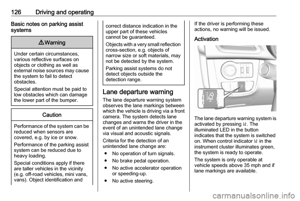
Activation
The lane departure warning system is activated by pressing ). The
illuminated LED in the button
indicates that the system is switched
on. When control indicator ) in the
instrument cluster illuminates green, the system is ready to operate.
The system is only operable at
vehicle speeds above 35 mph and if lane markings are available.
Page 154 of 201
152Vehicle careAfter having changed defective fusesclose the fuse box cover and press
until it engages.
If the fuse box cover is not closed
correctly, malfunction may occur.
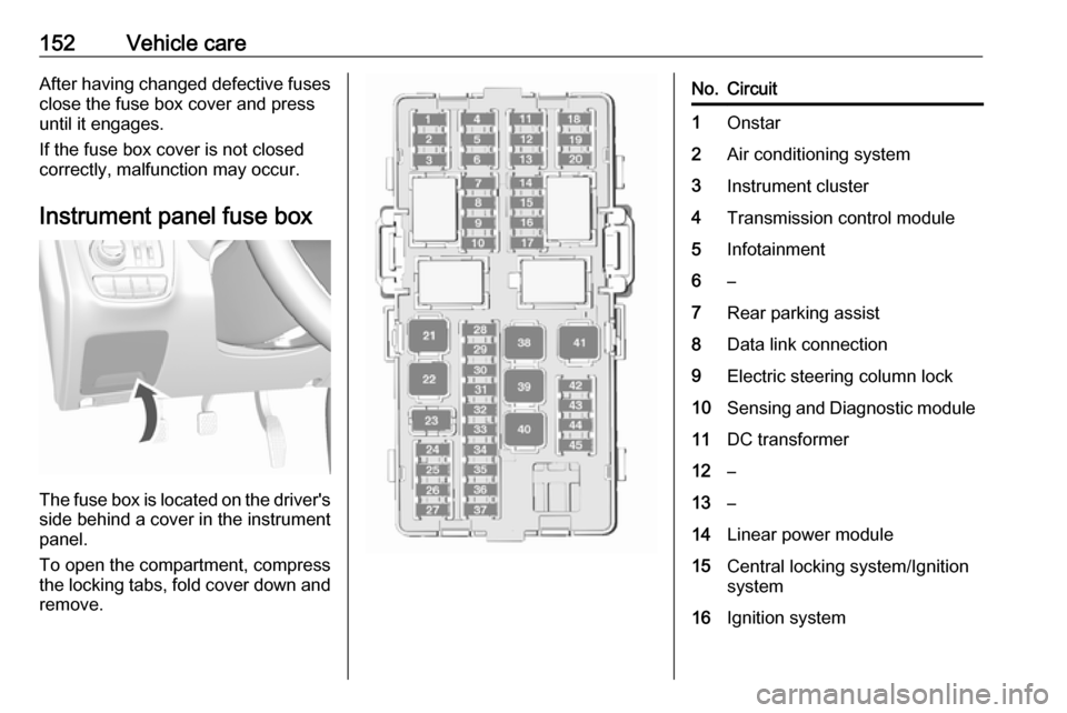
Instrument panel fuse box
The fuse box is located on the driver's
side behind a cover in the instrument
panel.
To open the compartment, compress
the locking tabs, fold cover down and
remove.
No.Circuit1Onstar2Air conditioning system3Instrument cluster4Transmission control module5Infotainment6–7Rear parking assist8Data link connection9Electric steering column lock10Sensing and Diagnostic module11DC transformer12–13–14Linear power module15Central locking system/Ignition
system16Ignition system
Page 155 of 201

Vehicle care153No.Circuit17–18Instrument cluster19–20Headlight range adjustment21Power windows, front22Power windows, rear23–24Manual transmission auto‐
mated module25Auxiliary power outlet26Sunroof27–28Body control module 829Body control module 730Body control module 631Body control module 532Body control module 4No.Circuit33Body control module 334Body control module 235Body control module 136–37Steering wheel control LED38–39Logistic/DC transformer40Power window, driver41Blower42Seat heating, front43Air conditioning module44Heated steering wheel45–Vehicle tools
Tools
Vehicles with tyre repair kit
The vehicle tools are in the
compartment under the floor cover in
the load compartment, together with
the tyre repair kit.