ESP VAUXHALL VIVARO 2014 User Guide
[x] Cancel search | Manufacturer: VAUXHALL, Model Year: 2014, Model line: VIVARO, Model: VAUXHALL VIVARO 2014Pages: 173, PDF Size: 4.11 MB
Page 103 of 173

Driving and operating101Brakes
The brake system comprises two
independent brake circuits.
If a brake circuit fails, the vehicle can
still be braked using the other brake
circuit. However, braking effect is
achieved only when you depress the
brake pedal firmly. You need to use
considerably more force for this. The
braking distance is extended. Seek
the assistance of a workshop before
continuing your journey.
When the engine is not running, the
support of the brake servo unit
disappears once the brake pedal has
been depressed once or twice.
Braking effect is not reduced, but
braking requires significantly greater
force. It is especially important to bear this in mind when being towed.
If control indicator R illuminates in
the instrument cluster while driving and the message BRAKING FAULT
appears in the Driver Information
Centre there is a fault in the braking
system. Seek the assistance of a
workshop immediately.Control indicator R 3 71.
Vehicle messages 3 75.
Antilock brake system Antilock brake system (ABS)
prevents the wheels from locking.
ABS starts to regulate brake pressure as soon as a wheel shows a tendency
to lock. The vehicle remains
steerable, even during hard braking.
ABS control is made apparent
through a pulse in the brake pedal
and the noise of the regulation
process.
For optimum braking, keep the brake
pedal fully depressed throughout the
braking process, despite the fact that
the pedal is pulsating. Do not reduce
the pressure on the pedal.
Control indicator u 3 72.
Fault If control indicator u does not go out
a few seconds after the ignition is
switched on, or if it illuminates while driving, there is a fault in the ABS.
Control indicator A may alsoilluminate in the instrument cluster
together with the messages CHECK
ABS and CHECK ESP in the Driver
Information Centre. The brake
system remains operational but
without ABS regulation.9 Warning
If there is a fault in the ABS, the
wheels may be liable to lock due
to braking that is heavier than
normal. The advantages of ABS are no longer available. During
hard braking, the vehicle can no longer be steered and may
swerve.
If control indicators u, A , R and
C illuminate, the ABS and ESP are
deactivated and the message
BRAKING FAULT is shown in the
Driver Information Centre. Seek the
assistance of a workshop.
Have the cause of the fault remedied
by a workshop.
Vehicle messages 3 75.
Page 104 of 173
102Driving and operatingParking brake
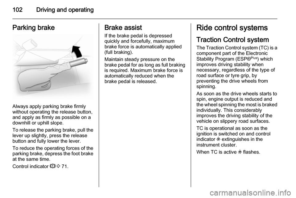
Always apply parking brake firmly
without operating the release button,
and apply as firmly as possible on a
downhill or uphill slope.
To release the parking brake, pull the lever up slightly, press the release
button and fully lower the lever.
To reduce the operating forces of the
parking brake, depress the foot brake
at the same time.
Control indicator R 3 71.
Brake assist
If the brake pedal is depressed
quickly and forcefully, maximum
brake force is automatically applied
(full braking).
Maintain steady pressure on the
brake pedal for as long as full braking
is required. Maximum brake force is
automatically reduced when the
brake pedal is released.Ride control systems
Traction Control system
The Traction Control system (TC) is a
component part of the Electronic
Stability Program (ESP® Plus
) which
improves driving stability when
necessary, regardless of the type of
road surface or tyre grip, by
preventing the drive wheels from
spinning.
As soon as the drive wheels starts to
spin, engine output is reduced and
the wheel spinning the most is braked
individually. This considerably
improves the driving stability of the
vehicle on slippery road surfaces.
TC is operational as soon as the
ignition is switched on and control
indicator v extinguishes in the
instrument cluster.
When TC is active v flashes.
Page 105 of 173
Driving and operating1039Warning
Do not let this special safety
feature tempt you into taking risks
when driving.
Adapt speed to the road
conditions.
Control indicator v 3 72.
Deactivation
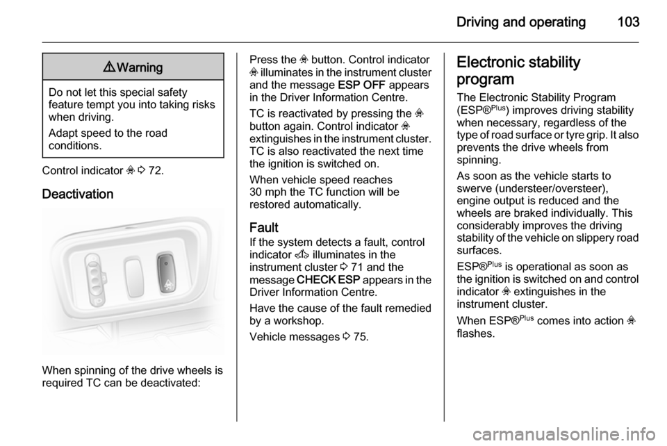
When spinning of the drive wheels is
required TC can be deactivated:
Press the v button. Control indicator
v illuminates in the instrument cluster
and the message ESP OFF appears
in the Driver Information Centre.
TC is reactivated by pressing the v
button again. Control indicator v
extinguishes in the instrument cluster.
TC is also reactivated the next time
the ignition is switched on.
When vehicle speed reaches
30 mph the TC function will be
restored automatically.
Fault If the system detects a fault, control
indicator A illuminates in the
instrument cluster 3 71 and the
message CHECK ESP appears in the
Driver Information Centre.
Have the cause of the fault remedied
by a workshop.
Vehicle messages 3 75.Electronic stability
program
The Electronic Stability Program
(ESP® Plus
) improves driving stability
when necessary, regardless of the
type of road surface or tyre grip. It also
prevents the drive wheels from
spinning.
As soon as the vehicle starts to
swerve (understeer/oversteer),
engine output is reduced and the
wheels are braked individually. This
considerably improves the driving
stability of the vehicle on slippery road
surfaces.
ESP® Plus
is operational as soon as
the ignition is switched on and control
indicator v extinguishes in the
instrument cluster.
When ESP® Plus
comes into action v
flashes.
Page 106 of 173
104Driving and operating9Warning
Do not let this special safety
feature tempt you into taking risks
when driving.
Adapt speed to the road
conditions.
Control indicator v 3 72.
Deactivation
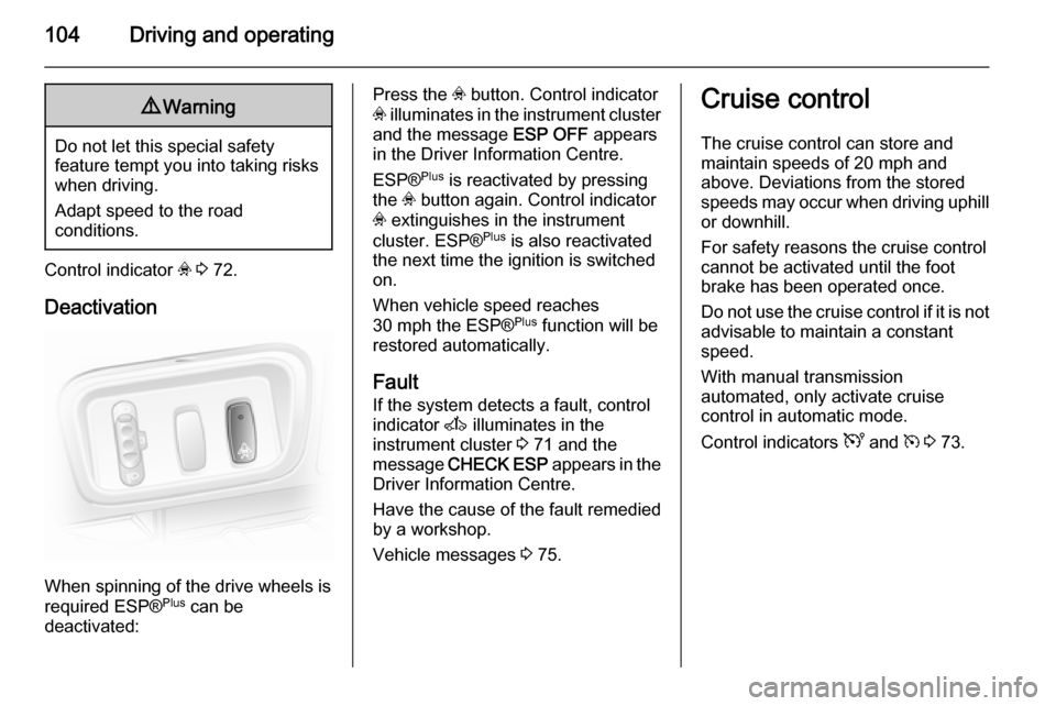
When spinning of the drive wheels is
required ESP® Plus
can be
deactivated:
Press the v button. Control indicator
v illuminates in the instrument cluster
and the message ESP OFF appears
in the Driver Information Centre.
ESP® Plus
is reactivated by pressing
the v button again. Control indicator
v extinguishes in the instrument
cluster. ESP® Plus
is also reactivated
the next time the ignition is switched on.
When vehicle speed reaches
30 mph the ESP® Plus
function will be
restored automatically.
Fault
If the system detects a fault, control
indicator A illuminates in the
instrument cluster 3 71 and the
message CHECK ESP appears in the
Driver Information Centre.
Have the cause of the fault remedied
by a workshop.
Vehicle messages 3 75.Cruise control
The cruise control can store and
maintain speeds of 20 mph and
above. Deviations from the stored
speeds may occur when driving uphill or downhill.
For safety reasons the cruise control cannot be activated until the foot
brake has been operated once.
Do not use the cruise control if it is not advisable to maintain a constant
speed.
With manual transmission
automated, only activate cruise
control in automatic mode.
Control indicators U and m 3 73.
Page 107 of 173
Driving and operating105
Activation
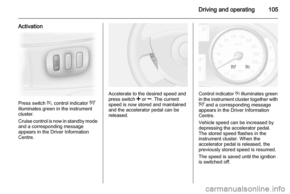
Press switch m, control indicator U
illuminates green in the instrument
cluster.
Cruise control is now in standby mode
and a corresponding message
appears in the Driver Information
Centre.
Accelerate to the desired speed and
press switch < or ]. The current
speed is now stored and maintained and the accelerator pedal can be
released.Control indicator m illuminates green
in the instrument cluster together with
U and a corresponding message
appears in the Driver Information
Centre.
Vehicle speed can be increased by depressing the accelerator pedal.
The stored speed flashes in the
instrument cluster. When the
accelerator pedal is released, the
previously stored speed is resumed.
The speed is saved until the ignition
is switched off.
Page 108 of 173
106Driving and operating
Increase speedWith cruise control active, the vehicle
speed can be increased continuously or in small increments by holding
down or tapping switch < repeatedly.
When the switch is released the
current speed is stored and
maintained.
Alternatively, accelerate to the
desired speed and store by pressing
switch <.
Reduce speed With cruise control active, the vehicle
speed can be decreased
continuously or in small increments
by holding down or tapping switch ]
repeatedly.
When the switch is released the
current speed is stored and
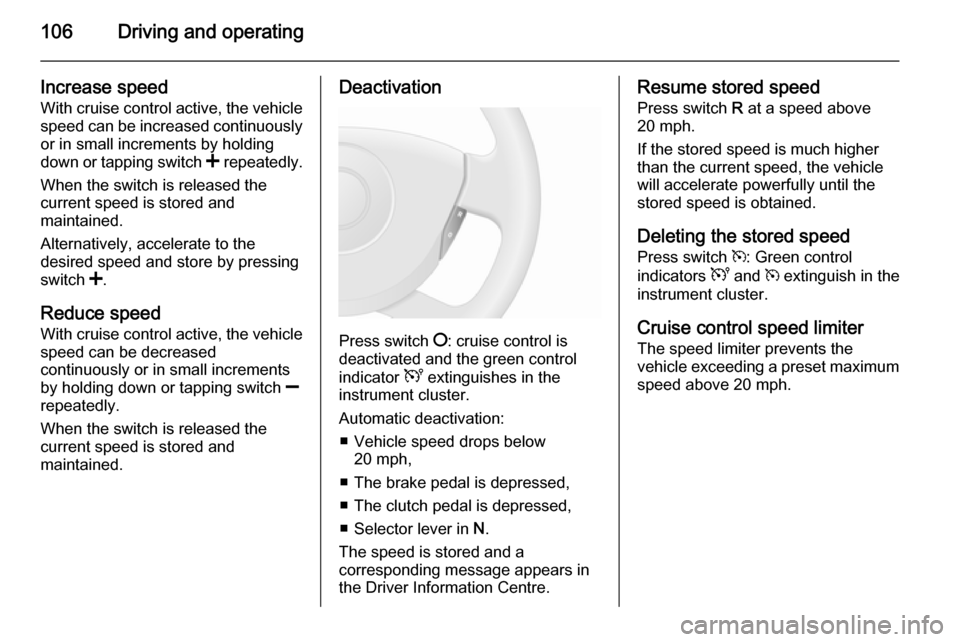
maintained.Deactivation
Press switch §: cruise control is
deactivated and the green control
indicator U extinguishes in the
instrument cluster.
Automatic deactivation: ■ Vehicle speed drops below 20 mph,
■ The brake pedal is depressed,
■ The clutch pedal is depressed,
■ Selector lever in N.
The speed is stored and a
corresponding message appears in
the Driver Information Centre.
Resume stored speed
Press switch R at a speed above
20 mph.
If the stored speed is much higher
than the current speed, the vehicle
will accelerate powerfully until the
stored speed is obtained.
Deleting the stored speed Press switch m: Green control
indicators U and m extinguish in the
instrument cluster.
Cruise control speed limiter
The speed limiter prevents the
vehicle exceeding a preset maximum
speed above 20 mph.
Page 109 of 173

Driving and operating107
Activation
Press switch U, control indicator U
illuminates yellow in the instrument
cluster.
Cruise control speed limiter function
is now in standby mode and a
corresponding message appears in
the Driver Information Centre.
Accelerate to the desired speed and
press switch < or ]. The current
speed is recorded.
The vehicle can be driven normally
but it will not be possible to exceed the programmed speed limit except in an
emergency.
Where the limit speed cannot be
maintained, e.g. when driving on a
steep decline, the limit speed will
flash in the Driver Information Centre.
Increase limit speed
The limit speed can be increased
continuously or in small increments
by holding down or tapping switch <
repeatedly.
Reduce limit speed
The limit speed can be decreased
continuously or in small increments
by holding down or tapping switch ]
repeatedly.
Exceeding the limit speed
In the event of an emergency, it is
possible to exceed the limit speed by
depressing the accelerator pedal
firmly beyond the point of resistance.
The limit speed will flash in the Driver Information Centre during this period.
Release the accelerator pedal and
the speed limiter function is
reactivated once a speed lower than the limit speed is obtained.Deactivation
Press switch §: Speed limiter is
deactivated and the vehicle can be
driven normally.
The limit speed is stored and a
corresponding message appears in
the Driver Information Centre.
Reactivation
Press switch R: The speed limiter
function is reactivated.
Deleting the limit speed
Press switch U: Yellow control
indicator U extinguishes in the
instrument cluster.
Page 110 of 173
108Driving and operatingObject detection
systems
Parking assist
The parking assist makes reverse
parking easier by measuring the
distance between the rear of the
vehicle and obstacles. It is the driver,
however, who bears full responsibility for parking.
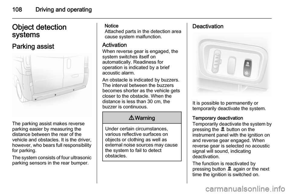
The system consists of four ultrasonic
parking sensors in the rear bumper.
Notice
Attached parts in the detection area
cause system malfunction.
Activation
When reverse gear is engaged, the
system switches itself on
automatically. Readiness for
operation is indicated by a brief
acoustic alarm.
An obstacle is indicated by buzzers.
The interval between the buzzers
becomes shorter as the vehicle gets
closer to the obstacle. When the
distance is less than 30 cm, the buzzer is continuous.9 Warning
Under certain circumstances,
various reflective surfaces on
objects or clothing as well as
external noise sources may cause the system to fail to detect
obstacles.
Deactivation
It is possible to permanently or
temporarily deactivate the system.
Temporary deactivation
Temporarily deactivate the system by
pressing the E button on the
instrument panel with the ignition on
and reverse gear engaged. When
reverse gear is selected no acoustic
signal will sound, indicating
deactivation.
The function is reactivated by
pressing button E again or the next
time the ignition is switched on.
Page 115 of 173

Driving and operating113
If the trailer starts snaking, drive moreslowly, do not attempt to correct the
steering and brake sharply if
necessary.
When driving downhill, drive in the
same gear as if driving uphill and
drive at a similar speed.
Adjust tyre pressure to the value
specified for full load 3 163.
Trailer towing Trailer loads
The permissible trailer loads are
vehicle and engine-dependent
maximum values which must not be exceeded. The actual trailer load is
the difference between the actual
gross weight of the trailer and the
actual coupling socket load with the
trailer coupled.
The permissible trailer loads are
specified in the vehicle documents. In general, they are valid for gradients
up to max. 12 %.The permitted trailer load applies up
to the specified incline and up to an
altitude of 1000 metres above sea
level. Since engine power decreases
as altitude increases due to the air
becoming thinner, therefore reducing
climbing ability, the permissible gross
train weight also decreases by 10 %
for every 1000 metres of additional
altitude. The gross train weight does
not have to be reduced when driving
on roads with slight inclines (less than 8 %, e.g. motorways).
The permissible gross train weight
must not be exceeded. This weight is
specified on the identification plate
3 150.
Vertical coupling load
The vertical coupling load is the load
exerted by the trailer on the coupling
ball. It can be varied by changing the
weight distribution when loading the
trailer.
The maximum permissible vertical
coupling load is specified on the
towing equipment identification plate
and in the vehicle documents. Always aim for the maximum load, especiallyin the case of heavy trailers. The
vertical coupling load should never
fall below 25 kg.
In the case of trailer loads of
1200 kg or more, the vertical coupling load should not be less than 50 kg.
Rear axle load When the trailer is coupled and the
towing vehicle fully loaded (including
all occupants), the permissible rear
axle load (see identification plate or
vehicle documents) must not be
exceeded.
Towing equipmentCaution
When operating without a trailer,
remove the coupling ball bar.
Page 119 of 173
Vehicle care117
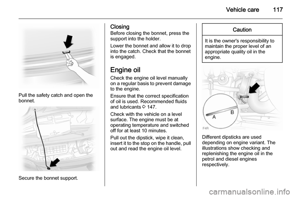
Pull the safety catch and open the
bonnet.
Secure the bonnet support.
Closing
Before closing the bonnet, press the
support into the holder.
Lower the bonnet and allow it to drop into the catch. Check that the bonnet
is engaged.
Engine oil
Check the engine oil level manually
on a regular basis to prevent damage
to the engine.
Ensure that the correct specification
of oil is used. Recommended fluids
and lubricants 3 147.
Check with the vehicle on a level
surface. The engine must be at
operating temperature and switched
off for at least 10 minutes.
Pull out the dipstick, wipe it clean,
insert it to the stop on the handle, pull
out and read the engine oil level.Caution
It is the owner's responsibility to
maintain the proper level of an
appropriate quality oil in the
engine.
Different dipsticks are used
depending on engine variant. The
illustrations show checking and
replenishing the engine oil in the
petrol and diesel engines
respectively.