Tool VAUXHALL VIVARO 2015.5 Owner's Manual
[x] Cancel search | Manufacturer: VAUXHALL, Model Year: 2015.5, Model line: VIVARO, Model: VAUXHALL VIVARO 2015.5Pages: 203, PDF Size: 4.54 MB
Page 25 of 203
Keys, doors and windows23
After use, reinsert the emergency
manual key in the housing of the
electronic key.
Door locks Anti-theft security lock
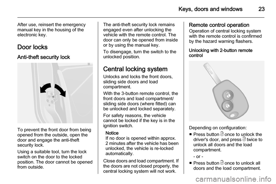
To prevent the front door from being
opened from the outside, open the
door and engage the anti-theft
security lock.
Using a suitable tool, turn the lock
switch on the door to the locked
position. The door cannot be opened
from outside.
The anti-theft security lock remains
engaged even after unlocking the
vehicle with the remote control. The
door can only be opened from inside
or by using the manual key.
To disengage, turn the switch to the
unlocked position.
Central locking system Unlocks and locks the front doors,
sliding side doors and load
compartment.
With the 3-button remote control, the
front doors and load compartment/
sliding side doors (where fitted) can
be unlocked and locked separately.
For safety reasons, the vehicle
cannot be locked if the key is in the
ignition switch.
Notice
If no door is opened within approx. 2 minutes after the vehicle has been
unlocked, the vehicle is re-locked
automatically.
Close doors and load compartment. If the doors are not closed properly, the
central locking system will not work.Remote control operation
Operation of central locking system
with the remote control is confirmed
by the hazard warning flashers.
Unlocking with 2-button remote
control
Depending on configuration:
■ Press button c once to unlock the
driver's door, and press c twice to
unlock all doors and the load
compartment.
- or -
■ Press button c once to unlock all
doors and the load compartment.
Page 30 of 203
28Keys, doors and windows
Handsfree operation is automatically
disabled when the central locking
switch e is pressed. To re-enable
handsfree operation, restart the
engine.
Electronic key system 3 21.
Slam door locks Certain models feature load
compartment locks which are isolated for added security.
With slam door locks, while the doors
can be locked and unlocked using the remote control or electronic key, the
load compartment must be manually
opened by turning the key in the lock.
Rear doors 3 29.
Automatic locking
Automatic locking after driving
off This security feature can be
configured to automatically lock the
doors and load compartment as soon
as the vehicle is driven.Activation
With the ignition switched on, press
and hold e on the central locking
switch for approx. 5 seconds. An audible signal confirms activation.
Deactivation
With the ignition switched on, press and hold e on the central locking
switch for approx. 5 seconds. An audible signal confirms deactivation.
Central locking switch 3 23.
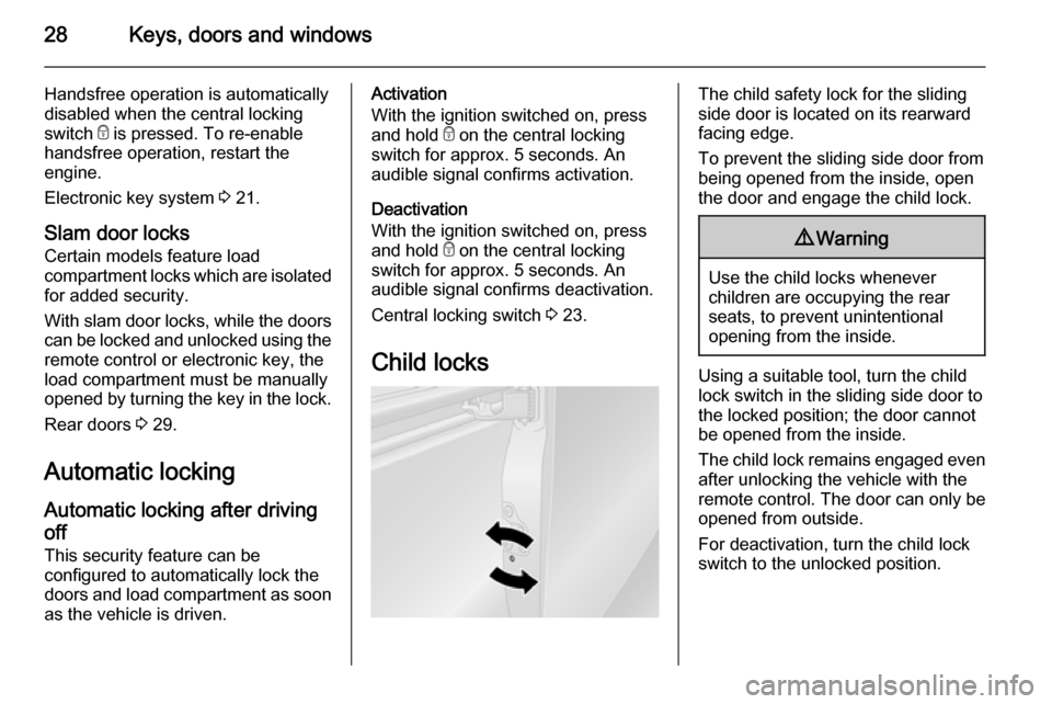
Child locksThe child safety lock for the sliding
side door is located on its rearward
facing edge.
To prevent the sliding side door from being opened from the inside, open
the door and engage the child lock.9 Warning
Use the child locks whenever
children are occupying the rear
seats, to prevent unintentional
opening from the inside.
Using a suitable tool, turn the child
lock switch in the sliding side door to
the locked position; the door cannot
be opened from the inside.
The child lock remains engaged even after unlocking the vehicle with the
remote control. The door can only be
opened from outside.
For deactivation, turn the child lock
switch to the unlocked position.
Page 138 of 203

136Vehicle careVehicle careGeneral Information...................136
Vehicle checks ........................... 137
Bulb replacement .......................145
Electrical system ........................150
Vehicle tools .............................. 155
Wheels and tyres .......................156
Jump starting ............................. 167
Towing ....................................... 168
Appearance care .......................170General Information
Accessories and vehicle
modifications
We recommend the use of Genuine Parts and Accessories and factory
approved parts specific for your
vehicle type. We cannot assess or guarantee reliability of other products
- even if they have a regulatory or
otherwise granted approval.
Do not make any modifications to the electrical system, e.g. changes of
electronic control units (chip tuning).Caution
When transporting the vehicle on
a train or on a recovery vehicle, the
mud flaps might be damaged.
Vehicle storage
Storage for a long period of time
If the vehicle is to be stored for several months:
■ Wash and wax the vehicle.
■ Have the wax in the engine compartment and underbody
checked.
■ Clean and preserve rubber seals.
■ Fill up fuel tank completely.
■ Change the engine oil.
■ Drain the washer fluid reservoir.
■ Check the coolant antifreeze and corrosion protection.
■ Adjust tyre pressure to the value specified for full load.
■ Park vehicle in a dry, well ventilated
place. Engage first or reverse gear.
Prevent the vehicle from rolling.
■ Do not apply the parking brake.
Page 149 of 203
Vehicle care147
4. Renew bulb and install bulbholder.
5. Install harness connector and access cover.
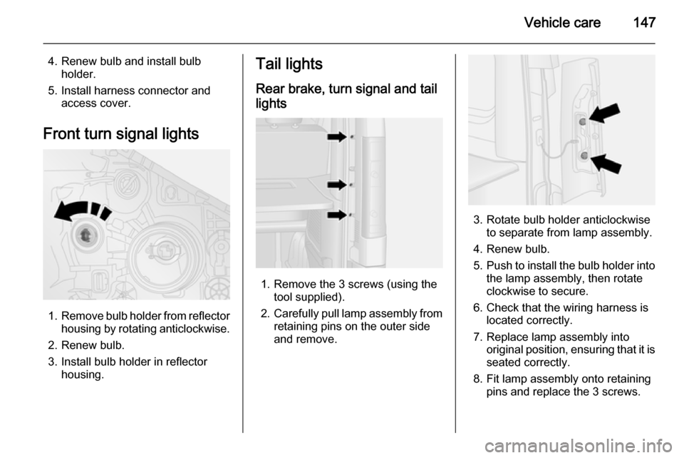
Front turn signal lights
1. Remove bulb holder from reflector
housing by rotating anticlockwise.
2. Renew bulb.
3. Install bulb holder in reflector housing.
Tail lights
Rear brake, turn signal and tail lights
1. Remove the 3 screws (using the tool supplied).
2. Carefully pull lamp assembly from
retaining pins on the outer side
and remove.
3. Rotate bulb holder anticlockwise to separate from lamp assembly.
4. Renew bulb.
5. Push to install the bulb holder into
the lamp assembly, then rotate
clockwise to secure.
6. Check that the wiring harness is located correctly.
7. Replace lamp assembly into original position, ensuring that it isseated correctly.
8. Fit lamp assembly onto retaining pins and replace the 3 screws.
Page 150 of 203
148Vehicle careSide turn signal lights
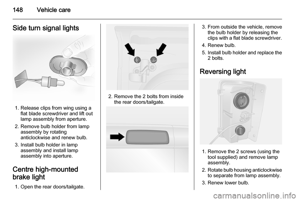
1. Release clips from wing using aflat blade screwdriver and lift out
lamp assembly from aperture.
2. Remove bulb holder from lamp assembly by rotating
anticlockwise and renew bulb.
3. Install bulb holder in lamp assembly and install lamp
assembly into aperture.
Centre high-mounted
brake light
1. Open the rear doors/tailgate.
2. Remove the 2 bolts from inside the rear doors/tailgate.
3. From outside the vehicle, remove the bulb holder by releasing the
clips with a flat blade screwdriver.
4. Renew bulb.
5. Install bulb holder and replace the
2 bolts.
Reversing light
1. Remove the 2 screws (using the tool supplied) and remove lamp
assembly.
2. Rotate bulb housing anticlockwise
to separate from lamp assembly.
3. Renew lower bulb.
Page 151 of 203
Vehicle care149
4.Push to install the bulb holder into
the lamp assembly, then rotate
clockwise to secure.
5. Install lamp assembly with the 2 screws.
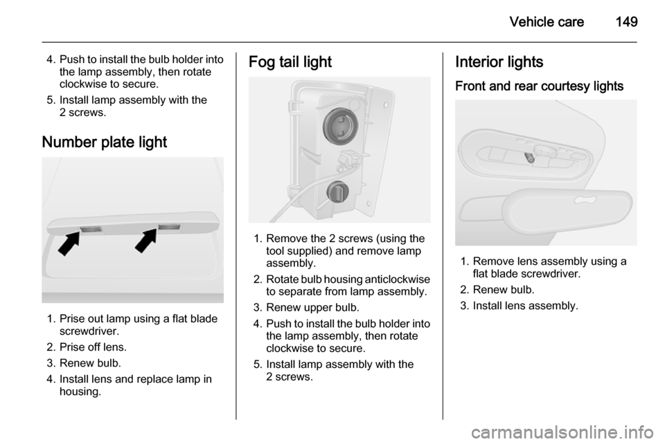
Number plate light
1. Prise out lamp using a flat blade screwdriver.
2. Prise off lens.
3. Renew bulb.
4. Install lens and replace lamp in housing.
Fog tail light
1. Remove the 2 screws (using thetool supplied) and remove lamp
assembly.
2. Rotate bulb housing anticlockwise
to separate from lamp assembly.
3. Renew upper bulb.
4. Push to install the bulb holder into
the lamp assembly, then rotate
clockwise to secure.
5. Install lamp assembly with the 2 screws.
Interior lights
Front and rear courtesy lights
1. Remove lens assembly using a flat blade screwdriver.
2. Renew bulb.
3. Install lens assembly.
Page 157 of 203
Vehicle care155
No.Circuit39Warning chimes40Load compartment power outlet41Driver power window42Rear power outlet43Starting, body control module44Heated seats45Heating, air conditioning46Windscreen wiper47TachographVehicle toolsTools
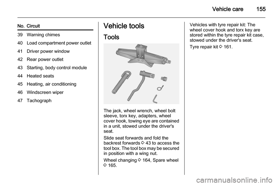
The jack, wheel wrench, wheel bolt
sleeve, torx key, adapters, wheel
cover hook, towing eye are contained
in a unit, stowed under the driver's
seat.
Slide seat forwards and fold the
backrest forwards 3 43 to access the
tool box. The tool box may be secured
in position with a wing nut.
Wheel changing 3 164, Spare wheel
3 165.
Vehicles with tyre repair kit: The
wheel cover hook and torx key are
stored within the tyre repair kit case,
stowed under the driver's seat.
Tyre repair kit 3 161.
Page 163 of 203
Vehicle care161
Tyre chains are only permitted on the
front wheels.
Always use fine mesh chains that add no more than 15 mm to the tyre tread
and the inboard sides (including chain lock).
For tyre size 215/60 R17, consult a
workshop.9 Warning
Damage may lead to tyre blowout.
Wheel covers on steel wheels may
come into contact with parts of the
chains. In such cases, remove the
wheel covers.
Tyre chains may only be used at
speeds up to 30 mph and, when
travelling on roads that are free of
snow, they may only be used for brief
periods since they are subject to rapid wear on a hard road and may snap.
The use of tyre chains is not permitted on the temporary spare wheel.
Tyre repair kit
Minor damage to the tyre tread or
sidewall can be repaired with the tyre
repair kit.
Do not remove foreign bodies from
the tyres.
Tyre damage exceeding 4 mm or that
is at tyre sidewall near the rim cannot
be repaired with the tyre repair kit.9 Warning
Do not drive faster than 50 mph.
Do not use for a lengthy period.
Steering and handling may be
affected.
If the vehicle has a flat tyre:
Apply the parking brake and engage
first gear or reverse gear.
The tyre repair kit is located under the
driver's seat. Vehicle tools 3 155.
1. Remove the compressor and sealant bottle from the tyre repairkit case.
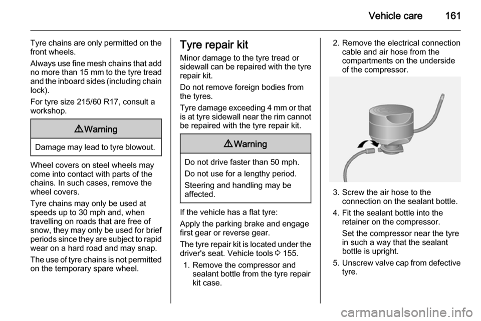
2. Remove the electrical connection cable and air hose from the
compartments on the underside
of the compressor.
3. Screw the air hose to the connection on the sealant bottle.
4. Fit the sealant bottle into the retainer on the compressor.
Set the compressor near the tyre
in such a way that the sealant
bottle is upright.
5. Unscrew valve cap from defective
tyre.
Page 166 of 203

164Vehicle care
Replace the used sealant bottle.Dispose of the sealant bottle as
prescribed by applicable laws.
Wheel changing
Some vehicles are equipped with a
tyre repair kit instead of a spare wheel 3 161.
Make the following preparations and
observe the following information:
■ Park the vehicle on a level, firm and
non-slippery surface. The front wheels must be in the straight-
ahead position.
■ Apply the parking brake and engage first gear or reverse gear.
■ Remove the spare wheel 3 165.
■ Never change more than one wheel
at a time.
■ Use the jack only to change wheels
in case of puncture, not for a
seasonal winter or summer tyre
change.
■ If the ground on which the vehicle is standing is soft, a solid board
(max. 1 cm thick) should be placed
under the jack.■ Take heavy objects out of the vehicle before jacking up.
■ No people or animals may be in the
vehicle when it is jacked-up.
■ Never crawl under a jacked-up vehicle.
■ Do not start the engine when the vehicle is raised on the jack.
1. Remove the wheel cover (using the hook supplied). Vehicle tools
3 155.
2. Loosen each of the wheel bolts by
half a turn using the wheel
wrench. Ensure the wrench
locates securely. The wrench
should turn anticlockwise to
loosen the bolts. Invert the wrench if necessary.
3. Place lifting pad spigot of the jack
under the jacking hole located
nearest the wheel concerned.
Ensure the jack is positioned
correctly. The jack base must be
on the ground directly below the
jacking hole in a manner that
prevents it from slipping.
4. Install wrench onto the jack and raise the vehicle by turning the
wrench until the wheel is clear of
the ground.
Page 167 of 203

Vehicle care165
5. Unscrew wheel bolts completelyby turning anticlockwise and wipe
clean with a cloth.
Put wheel bolts somewhere
where the threads will not be
soiled.
6. Change the wheel. Spare wheel 3 165.
7. Screw in the wheel bolts.
8. Lower the vehicle and remove jack.
9. Tighten each of the wheel bolts in
a crosswise sequence using the
wheel wrench. Ensure the wrench locates securely. The wrench
should turn clockwise to tighten
the bolts. Invert the wrench if
necessary.
Tightening torque is 160 Nm.
10. Replace the wheel cover, ensuring that the valve hole in thewheel cover is aligned with the
tyre valve before installing.Notice
If applicable, fit anti-theft bolts
nearest the tyre valve (otherwise it
may not be possible to refit the wheel
cover).
11. Stow the replaced wheel 3 165
and the vehicle tools 3 155.
12. Have the new wheel balanced on the vehicle.
Check the tyre pressure of the
installed tyre 3 190.
Check the wheel bolt torque.
Have the defective tyre renewed or
repaired as soon as possible.
Spare wheel
Some vehicles are equipped with a
tyre repair kit instead of a spare wheel 3 161.
If mounting a spare wheel which is
different from the other wheels, this
wheel might be classified as a
temporary spare wheel and the
corresponding speed limits apply,even though no label indicates this.
Seek the assistance of a workshop to
check the applicable speed limit.Caution
The use of a spare wheel that is smaller than the other wheels or in combination with winter tyres
could affect driveability. Have the defective tyre replaced as soon as
possible.
It may be necessary to jack the
vehicle up to gain access to the spare
wheel on a fully loaded vehicle with a flat rear tyre.
Wheel changing 3 164.