headlights VAUXHALL VIVARO 2015.5 Owner's Manual
[x] Cancel search | Manufacturer: VAUXHALL, Model Year: 2015.5, Model line: VIVARO, Model: VAUXHALL VIVARO 2015.5Pages: 203, PDF Size: 4.54 MB
Page 14 of 203
12In brief
Instrument panel
illumination control ................96
Auxiliary heater ...................104
Speed limiter ....................... 128Exterior lighting
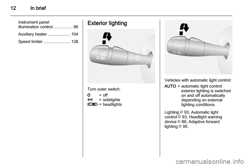
Turn outer switch:
7=off8=sidelights9P=headlights
Vehicles with automatic light control:
AUTO=automatic light control:
exterior lighting is switched
on and off automatically
depending on external
lighting conditions.
Lighting 3 93, Automatic light
control 3 93, Headlight warning
device 3 89, Adaptive forward
lighting 3 95.
Page 89 of 203
Instruments and controls87
3. Move out of the flow of traffic asquickly as possible without
impeding other vehicles.
4. Switch off ignition.9 Warning
When the engine is off,
considerably more force is needed
to brake and steer.
Do not remove key until vehicle is stationary, otherwise the steering
wheel lock could engage
unexpectedly.
Check oil level before seeking
assistance of a workshop 3 138.
Fuel economy mode
ECO illuminates green when ECO
mode is engaged to reduce fuel
consumption.
ECO mode, driving economically
3 110.
Low fuel
Y illuminates yellow.
When the ignition is switched on, the control indicator illuminates briefly.
Illuminates when level in fuel tank is
low (range of approx. 30 miles); refuel
immediately 3 132.
Catalytic converter 3 118.
Bleeding the diesel fuel system
3 144.
Autostop
D illuminates when engine is in an
Autostop.
Stop-start system 3 115.
Exterior light
9 illuminates green.
Illuminated when the headlights are on.
8 illuminates green.
Illuminated when the sidelights are
on.
Lighting 3 93.High beam
P illuminates blue.
Illuminated when high beam is on and during headlight flash 3 94.
Fog light > illuminates green.
Illuminated when the front fog lights
are on 3 96.
Rear fog light
r illuminates green.
Illuminated when the rear fog light is
on 3 96.
Cruise control
m , U illuminates green or yellow.
m illuminates green when a certain
speed is stored.
U illuminates green when the system
is on.
Speed limiter
U illuminates yellow.
Page 95 of 203
Lighting93LightingExterior lighting............................ 93
Interior lighting ............................. 96
Lighting features ..........................98Exterior lighting
Light switch
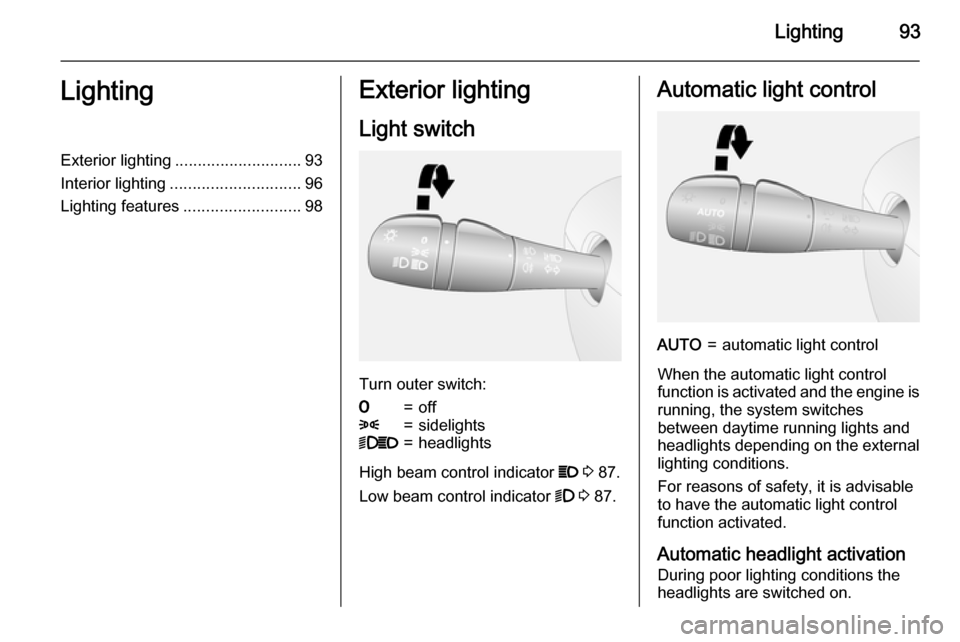
Turn outer switch:
7=off8=sidelights9P=headlights
High beam control indicator P 3 87.
Low beam control indicator 9 3 87.
Automatic light controlAUTO=automatic light control
When the automatic light control
function is activated and the engine is running, the system switches
between daytime running lights and headlights depending on the external lighting conditions.
For reasons of safety, it is advisable
to have the automatic light control
function activated.
Automatic headlight activation
During poor lighting conditions the
headlights are switched on.
Page 96 of 203
94Lighting
Daytime running lights 3 95.
High beam
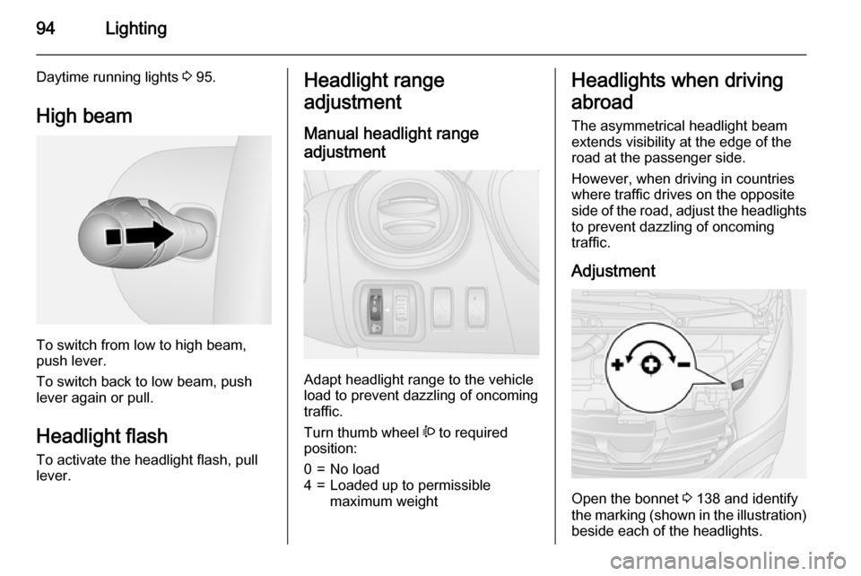
To switch from low to high beam,
push lever.
To switch back to low beam, push
lever again or pull.
Headlight flash
To activate the headlight flash, pull
lever.
Headlight range
adjustment
Manual headlight range
adjustment
Adapt headlight range to the vehicle
load to prevent dazzling of oncoming
traffic.
Turn thumb wheel ? to required
position:
0=No load4=Loaded up to permissible
maximum weightHeadlights when driving
abroad
The asymmetrical headlight beam
extends visibility at the edge of the
road at the passenger side.
However, when driving in countries
where traffic drives on the opposite
side of the road, adjust the headlights to prevent dazzling of oncoming
traffic.
Adjustment
Open the bonnet 3 138 and identify
the marking (shown in the illustration)
beside each of the headlights.
Page 98 of 203
96Lighting
If the lever is moved past the first stop,the turn signal is switched on
constantly. Switch the turn signal off
manually by moving the lever to its
original position.
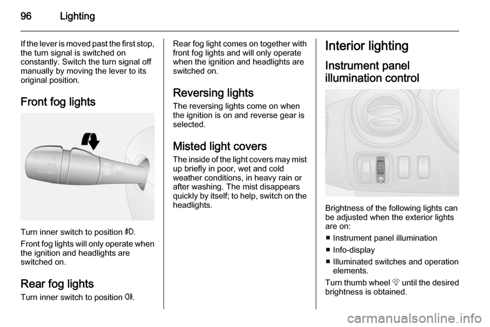
Front fog lights
Turn inner switch to position >.
Front fog lights will only operate when
the ignition and headlights are
switched on.
Rear fog lights Turn inner switch to position r.
Rear fog light comes on together with
front fog lights and will only operate
when the ignition and headlights are
switched on.
Reversing lights The reversing lights come on when
the ignition is on and reverse gear is
selected.
Misted light covers The inside of the light covers may mistup briefly in poor, wet and cold
weather conditions, in heavy rain or
after washing. The mist disappears
quickly by itself; to help, switch on the
headlights.Interior lighting
Instrument panel
illumination control
Brightness of the following lights can
be adjusted when the exterior lights
are on:
■ Instrument panel illumination
■ Info-display
■ Illuminated switches and operation elements.
Turn thumb wheel b until the desired
brightness is obtained.
Page 100 of 203
98LightingLighting featuresEntry lighting
Welcome lighting Vehicle lights are switched on for a
short time to facilitate locating the
vehicle when it is dark.
Remote control operation
Lights switch on when unlocking the
vehicle with the remote control.
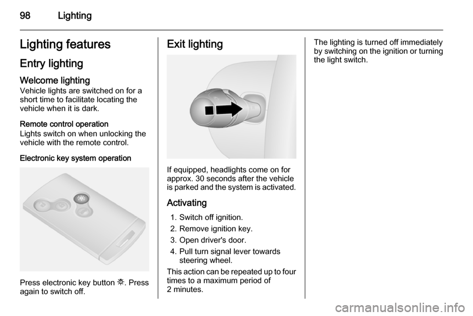
Electronic key system operation
Press electronic key button t. Press
again to switch off.
Exit lighting
If equipped, headlights come on for
approx. 30 seconds after the vehicle
is parked and the system is activated.
Activating 1. Switch off ignition.
2. Remove ignition key.
3. Open driver's door.
4. Pull turn signal lever towards steering wheel.
This action can be repeated up to four
times to a maximum period of
2 minutes.
The lighting is turned off immediately
by switching on the ignition or turning
the light switch.
Page 133 of 203
Driving and operating131
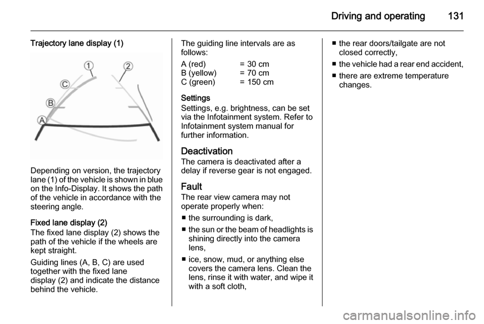
Trajectory lane display (1)
Depending on version, the trajectory
lane (1) of the vehicle is shown in blue
on the Info-Display. It shows the path of the vehicle in accordance with the
steering angle.
Fixed lane display (2)
The fixed lane display (2) shows the
path of the vehicle if the wheels are
kept straight.
Guiding lines (A, B, C) are used together with the fixed lane
display (2) and indicate the distance
behind the vehicle.
The guiding line intervals are as
follows:A (red)=30 cmB (yellow)=70 cmC (green)=150 cm
Settings
Settings, e.g. brightness, can be set via the Infotainment system. Refer to
Infotainment system manual for
further information.
Deactivation
The camera is deactivated after a
delay if reverse gear is not engaged.
Fault The rear view camera may notoperate properly when:
■ the surrounding is dark,
■ the sun or the beam of headlights is
shining directly into the camera
lens,
■ ice, snow, mud, or anything else covers the camera lens. Clean the
lens, rinse it with water, and wipe it
with a soft cloth,
■ the rear doors/tailgate are not closed correctly,
■ the vehicle had a rear end accident,
■ there are extreme temperature changes.
Page 148 of 203
146Vehicle careHeadlights
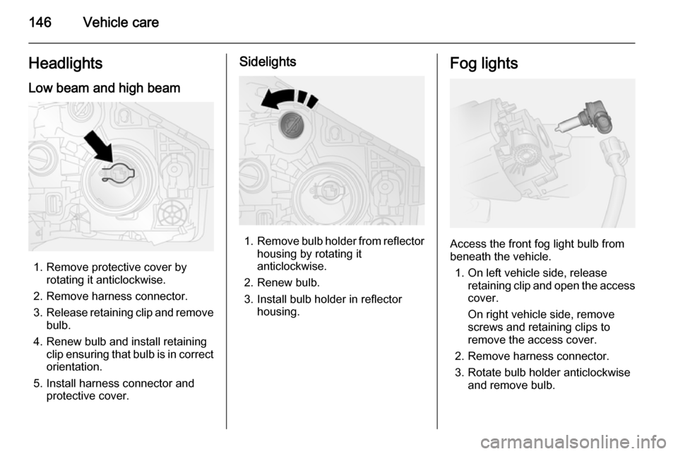
Low beam and high beam
1. Remove protective cover by rotating it anticlockwise.
2. Remove harness connector.
3. Release retaining clip and remove
bulb.
4. Renew bulb and install retaining clip ensuring that bulb is in correctorientation.
5. Install harness connector and protective cover.
Sidelights
1.Remove bulb holder from reflector
housing by rotating it
anticlockwise.
2. Renew bulb.
3. Install bulb holder in reflector housing.
Fog lights
Access the front fog light bulb from
beneath the vehicle.
1. On left vehicle side, release retaining clip and open the accesscover.
On right vehicle side, remove screws and retaining clips to
remove the access cover.
2. Remove harness connector.
3. Rotate bulb holder anticlockwise and remove bulb.
Page 170 of 203
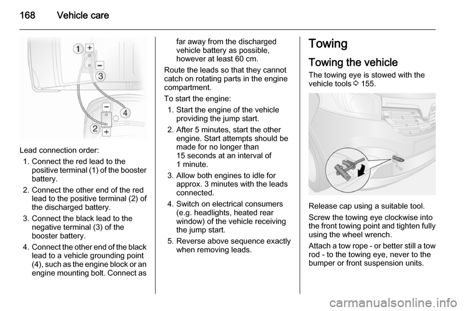
168Vehicle care
Lead connection order:1. Connect the red lead to the positive terminal (1) of the booster
battery.
2. Connect the other end of the red lead to the positive terminal (2) of
the discharged battery.
3. Connect the black lead to the negative terminal (3) of the
booster battery.
4. Connect the other end of the black
lead to a vehicle grounding point
(4), such as the engine block or an
engine mounting bolt. Connect as
far away from the discharged
vehicle battery as possible,
however at least 60 cm.
Route the leads so that they cannot
catch on rotating parts in the engine
compartment.
To start the engine: 1. Start the engine of the vehicle providing the jump start.
2. After 5 minutes, start the other engine. Start attempts should be
made for no longer than
15 seconds at an interval of
1 minute.
3. Allow both engines to idle for approx. 3 minutes with the leads
connected.
4. Switch on electrical consumers (e.g. headlights, heated rear
window) of the vehicle receiving
the jump start.
5. Reverse above sequence exactly when removing leads.Towing
Towing the vehicle The towing eye is stowed with thevehicle tools 3 155.
Release cap using a suitable tool.
Screw the towing eye clockwise into
the front towing point and tighten fully
using the wheel wrench.
Attach a tow rope - or better still a tow rod - to the towing eye, never to the
bumper or front suspension units.
Page 198 of 203

196
Front door pockets........................ 66
Front fog lights ........................ 93, 96
Front seats.................................... 42 Front storage ................................ 66
Front turn signal lights ...............147
Fuel consumption - CO 2-
Emissions ............................... 133
Fuel cut-off system .....................115
Fuel economy gauge ....................80
Fuel economy mode .....................87
Fuel economy rating ...............89, 90
Fuel for diesel engines ..............132
Fuel gauge ................................... 80 Fuse box ..................................... 152
Fuses ......................................... 150
G Gauges ......................................... 78
General information ...................134
Glovebox ..................................... 65
Glovebox cooler ......................... 108
Glove box lighting .........................97
H Hand brake - see Parking brake. 121
Hazard warning flashers ..............95
Headlight flash ............................. 94
Headlight range adjustment ........94
Headlights ...................... 93, 94, 146
Headlights when driving abroad ..94Head restraint adjustment .............8
Head restraints ............................ 41
Heated exterior mirrors .................15
Heated mirrors ............................. 37
Heated rear window ...............15, 40
Heating ........................................ 45
Heating and ventilation system ...99
High beam ............................. 87, 94
Hill start assist ........................... 121
Horn ....................................... 14, 74
I
Identification plate .....................177
Idle speed control .......................114
Ignition switch positions .............112
Immobiliser .................................. 35
Indicators ...................................... 78
Info-display ................................... 88
Information displays...................... 88
Initial drive information.................... 6
Instrument cluster ........................78
Instrument panel fuse box .........152
Instrument panel illumination .....150
Instrument panel illumination control ...................................... 96
Instrument panel overview ........... 10
Instrument panel storage ..............65
Interior care ............................... 171
Interior lighting .............................. 96
Interior lights ........................ 97, 149Interior mirrors.............................. 37
Introduction .................................... 3
Isofix child restraint systems ........ 64
J Jack ............................................ 155
Journey record.............................. 90
Jump starting ............................. 167
K Keys ............................................. 19
Keys, locks ................................... 19
L
Lashing eyes ............................... 69
Light covers, misted...................... 96
Lighting ......................................... 93
Lighting features ........................... 98
Light switch .................................. 93
Load compartment ....................... 31
Load compartment cover .............68
Load compartment lighting ...........97
Loading information .....................71
Load-through feature ....................67
Low fuel ....................................... 87
M
Malfunction indicator light ............84
Manual adjustment ......................36
Manual anti-dazzle ......................37