sensor VAUXHALL VIVARO 2018.5 Owner's Manual
[x] Cancel search | Manufacturer: VAUXHALL, Model Year: 2018.5, Model line: VIVARO, Model: VAUXHALL VIVARO 2018.5Pages: 239, PDF Size: 5.75 MB
Page 16 of 239
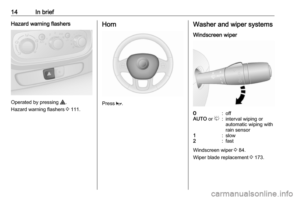
14In briefHazard warning flashers
Operated by pressing ¨.
Hazard warning flashers 3 111.
Horn
Press j.
Washer and wiper systems
Windscreen wiper7:offAUTO or P:interval wiping or
automatic wiping with
rain sensor1:slow2:fast
Windscreen wiper 3 84.
Wiper blade replacement 3 173.
Page 43 of 239

Keys, doors and windows41Automatic anti-dazzle
Dazzle from following vehicles at
night is automatically reduced.
Windows
Windscreen Heat-reflecting windscreenThe heat-reflecting windscreen has a
coating which reflects solar radiation.
Also data signals, e.g. from toll
stations, might be reflected.
The marked areas on the windscreen are not covered with the coating.
Devices for electronic data recording
and fee payment must be attached in
these areas. Otherwise data
recording malfunctions may occur.
Windscreen stickers
Do not attach stickers such as toll
road stickers or similar on the
windscreen in the area of the interior
mirror.
Windscreen replacementCaution
If the vehicle has a front-looking
camera sensor for the driver
assistance systems, it is very
important that any windscreen
replacement is performed
accurately according to Vauxhall
specifications. Otherwise, these systems may not work properly
and there is a risk of unexpected
behaviour and/or messages from
these systems.
Page 60 of 239
58Seats, restraintsAirbag systemThe airbag system consists of a
number of individual systems
depending on the scope of
equipment.
When triggered, the airbags inflate
within milliseconds. They also deflate
so quickly that it is often unnoticeable during the collision.9 Warning
As the airbag system deploys in an
explosive manner, repairs must be
performed by skilled personnel
only.
9 Warning
Adding accessories that change
the vehicle's frame, bumper
system, height, front end or side
sheet metal, may keep the airbag
system from working properly. The operation of the airbag system can
also be affected by changing any
parts of the front seats, seat belts,
airbag sensing and diagnostic
module, steering wheel,
instrument panel, inner door seals including the speakers, any of the
airbag modules, ceiling or pillar
trim, front sensors, side impact
sensors or airbag wiring.
Notice
The airbag systems and belt
pretensioner control electronics are
located in the centre console area.
Do not put any magnetic objects in
this area.
Do not affix any objects onto the
airbag covers and do not cover them with other materials. Have damagedcovers replaced by a workshop.
Each airbag is triggered only once.
Have deployed airbags replaced by
a workshop. Furthermore, it may be
necessary to have the steering
wheel, the instrument panel, parts of
the panelling, the door seals,
handles and the seats replaced.
Do not make any modifications to
the airbag system as this will
invalidate the vehicle operating
permit.
Control indicator v for airbag systems
3 96.
Child restraint systems on front
passenger seat with airbag
systems
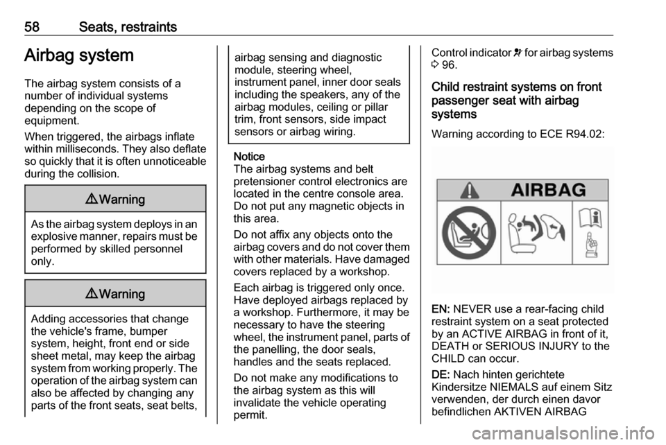
Warning according to ECE R94.02:
EN: NEVER use a rear-facing child
restraint system on a seat protected
by an ACTIVE AIRBAG in front of it,
DEATH or SERIOUS INJURY to the
CHILD can occur.
DE: Nach hinten gerichtete
Kindersitze NIEMALS auf einem Sitz
verwenden, der durch einen davor
befindlichen AKTIVEN AIRBAG
Page 86 of 239
84Instruments and controlsWindscreen wiper andwasher
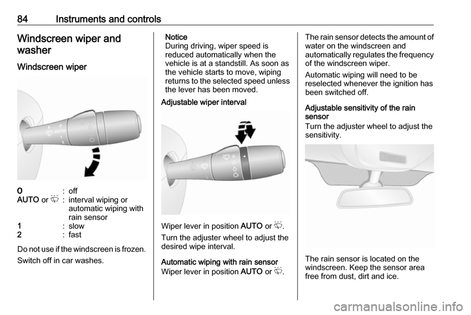
Windscreen wiper7:offAUTO or P:interval wiping or
automatic wiping with
rain sensor1:slow2:fast
Do not use if the windscreen is frozen.
Switch off in car washes.
Notice
During driving, wiper speed is
reduced automatically when the
vehicle is at a standstill. As soon as
the vehicle starts to move, wiping
returns to the selected speed unless the lever has been moved.
Adjustable wiper interval
Wiper lever in position AUTO or P.
Turn the adjuster wheel to adjust the
desired wipe interval.
Automatic wiping with rain sensor
Wiper lever in position AUTO or P.
The rain sensor detects the amount of
water on the windscreen and
automatically regulates the frequency
of the windscreen wiper.
Automatic wiping will need to be
reselected whenever the ignition has
been switched off.
Adjustable sensitivity of the rain
sensor
Turn the adjuster wheel to adjust the
sensitivity.
The rain sensor is located on the
windscreen. Keep the sensor area
free from dust, dirt and ice.
Page 101 of 239

Instruments and controls99Illuminates red when the engine isrunning
Stop, switch off engine.Caution
Coolant temperature too high.
Check coolant level 3 168.
If there is sufficient coolant, consult a workshop.
The control indicator must be blue
before continuing driving.
Preheating
! illuminates yellow.
Preheating is activated. Only
activates when outside temperature
is low.
AdBlue Y illuminates yellow.
AdBlue level is low. Refill AdBlue as
soon as possible, to avoid prevention
of engine starts.
Illuminates together with control
indicator j to indicate a system
failure or as a warning that engine starting may not be possible after a
certain distance. Seek the assistance
of a workshop immediately.
A corresponding message appears in the Driver Information Centre 3 101.
AdBlue percentage remaining can
also be checked by pressing button
repeatedly on end of wiper lever.
Trip computer 3 104.
AdBlue 3 140.
Tyre pressure monitoring system
w illuminates or flashes yellow.
Illuminates briefly when the ignition is
switched on.
Illuminates
Tyre pressure loss. Stop immediately
and check tyre pressure.
Control indicator w illuminates
together with C 3 97 and a
corresponding message appears inthe Driver Information Centre when a puncture or severely under-inflated
tyre is detected.
Flashes
Fault in system. After a delay the
control indicator illuminates
continuously. Consult a workshop.
Control indicator w illuminates
together with A 3 97 and a
corresponding message appears in
the Driver Information Centre when a
tyre without a pressure sensor is
mounted (e.g. spare wheel).
Tyre pressure monitoring system
3 187.
Engine oil pressure
I illuminates red.
Illuminates briefly when the ignition is
switched on.
Page 127 of 239

Climate control125Open the cover and replace the
battery (Type A: CR 2430, Type B:
2CR 11108, or equivalent), ensuring
the new battery is correctly installed
with the positive ( <) side facing the
positive terminals. Replace the cover securely.
Dispose of old batteries in
accordance with environmental
regulations.
Batteries do not belong in household
waste. They must be disposed of at
an appropriate recycling collection
point.
Operation (Type A)
Heating Y
Select Y in the menu bar and press
G to confirm. The predetermined
heating duration, e.g. L 30, flashes in
the display. The factory setting is 30 minutes.
Adjust the heating duration using k
or l and confirm. The value can be
set from ten to 120 minutes. Due to
the power consumption, note the
heating duration.
To switch off, select Y in the menu bar
again and press d.
Programming P
Up to three preset departure times
can be programmed, either during
one day or over one week.
● Select P in the menu bar and
press G to confirm.
● Select desired preset memory number P1, P2 or P3 and
confirm.
● Select F and confirm.
● Select weekday or weekday group and confirm.
● Select hour and confirm.
● Select minutes and confirm.
● Select Y and confirm.
● Select ECO or HIGH and confirm.
● Select duration and confirm.
● Press d to exit.Repeat the procedure to programme
the other preset memory numbers if
required.
To activate a desired preset memory
number select P1, P2 or P3, then
select On and confirm.
When a program is activated P and
Y will be displayed together.
To deactivate a preset memory,
select P1, P2 or P3, then select Off
and confirm.
Heating stops automatically
5 minutes after the programmed
departure time.
Notice
The remote control system features a temperature sensor which
calculates the runtime according to the ambient temperature and thedesired heating level (ECO or
HIGH). The system starts
automatically between five and
60 minutes prior to the programmed
departure time.
Set time and weekday Þ
If the vehicle battery is disconnected or its voltage is too low, the unit will
need to be reset.
Page 137 of 239

Driving and operating135Resetting with electronic key
system
To reset the fuel cut-off system and
enable the vehicle to be driven:
1. Insert the electronic key in the card reader 3 131.
2. Press START/STOP without
depressing any pedals.
3. Wait a few minutes to allow the fuel system to be reset.
If the engine does not start, repeat the procedure.
Electronic key system 3 21.
Power button 3 131.
Refuelling 3 159.
Overrun cut-off The fuel supply is automatically cut off
during overrun, i.e. when the vehicle
is driven with a gear engaged but
accelerator pedal is released.
Depending on driving conditions, the
overrun cut-off may be deactivated.Stop-start system
The stop-start system helps to save
fuel and to reduce the exhaust
emissions. When conditions allow, it
switches off the engine as soon as the
vehicle is at a low speed or at a
standstill, e.g. at a traffic light or in a
traffic jam. It restarts the engine
automatically as soon as the clutch pedal is depressed.
A vehicle battery sensor ensures that
an Autostop is only performed if the
vehicle battery is sufficiently charged
for a restart.
Switch off engine and ignition before
exiting the vehicle.
Activation
The stop-start system is available as
soon as the engine is started, the
vehicle starts-off and the conditions
as stated below in this section are
fulfilled.
If the below conditions are not
fulfilled, an Autostop is prohibited and
control indicator \ illuminates in the
instrument cluster 3 100.Deactivation
Deactivate the stop-start system
manually by pressing Î. LED in the
button illuminates to indicate
deactivation and a corresponding message appears in the Driver
Information Centre 3 101.
If deactivated manually, it is possible to reactivate the stop-start system by
pressing Î again. The LED
extinguishes in the button and a
corresponding message appears in
the Driver Information Centre. The
system is reactivated automatically
the next time the ignition is switched
on.
Page 156 of 239
154Driving and operatingPressing < will also reactivate the
speed limiter function, but at the
current vehicle speed only, not the
stored speed.
Switching off the system
Press U. The yellow control indicator
U extinguishes in the instrument
cluster.
Maximum speed limiter
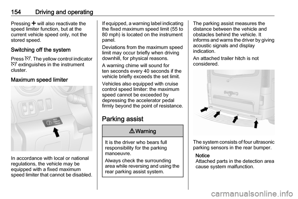
In accordance with local or national
regulations, the vehicle may be
equipped with a fixed maximum
speed limiter that cannot be disabled.
If equipped, a warning label indicating the fixed maximum speed limit (55 to
80 mph) is located on the instrument
panel.
Deviations from the maximum speed
limit may occur briefly when driving
downhill, for physical reasons.
A warning chime will sound for
ten seconds every 40 seconds if the vehicle briefly exceeds the set limit.
Vehicles also equipped with cruise
control speed limiter: the maximum
speed cannot be exceeded by
depressing the accelerator pedal
firmly beyond the point of resistance.
Parking assist9 Warning
It is the driver who bears full
responsibility for the parking
manoeuvre.
Always check the surrounding
area while reversing and using the rear parking assist system.
The parking assist measures the
distance between the vehicle and
obstacles behind the vehicle. It
informs and warns the driver by giving acoustic signals and display
indication.
An attached trailer hitch is not
considered.
The system consists of four ultrasonic parking sensors in the rear bumper.
Notice
Attached parts in the detection area
cause system malfunction.
Page 158 of 239
156Driving and operatingand j illuminates in the instrument
cluster 3 97. Consult a workshop to
have the cause of the fault remedied.Caution
When reversing, the area should
be free from obstacles which could impact on the underside of the
vehicle.
Impact to the rear axle, which may
not be visible, could lead to
uncharacteristic changes in the
vehicle handling. In the event of
such an impact, consult a
workshop.
Vehicle messages 3 102.
Basic notes on parking assist
system
9 Warning
Under certain circumstances,
various reflective surfaces on
objects or clothing as well as
external noise sources may cause the system to fail to detect
obstacles.
Special attention must be paid to
low obstacles which can damage
the lower part of the bumper.Caution
Performance of the sensors can
be reduced when sensors are
covered, e.g. by ice or snow.
Performance of the parking assist
system can be reduced due to
heavy loading.
Special conditions apply if there
are taller vehicles involved (e.g.
off-road vehicles, mini vans,
vans). Object identification in the
upper part of these vehicles
cannot be guaranteed.
Objects with a very small reflection
cross-section, e.g. objects of
narrow size or soft materials, may
not be detected by the system.
The parking assist system will not
detect objects which are out of the detection range of the sensors.
Rear view camera
The rear view camera assists the
driver when reversing by displaying a view of the area behind the vehicle in
either the interior mirror or the Info
Display.
9 Warning
The rear view camera does not
replace driver vision. Note that
objects that are outside the
camera's field of view, e.g. below
the bumper or underneath the
vehicle, are not displayed.
Do not reverse the vehicle by only looking at the display and checkthe surrounding area behind and
around the vehicle before
reversing.
Page 189 of 239
Vehicle care187Trailer towingWhen towing a trailer with a fully
laden vehicle, the tyre pressure must
be increased by 20 kPa/0.2 bar
(3.0 psi) and the maximum speed
limited to 60 mph.
Trailer towing 3 161.
Tyre pressure monitoring
system
The tyre pressure monitoring system
uses radio and sensor technology to
check tyre pressure levels.Caution
Tyre pressure monitoring system
warns only about low tyre pressure condition and does not replace
regular tyre maintenance by the
driver.
All wheels must be equipped with pressure sensors and the tyres must
have the prescribed pressure.
Notice
In countries where the tyre pressure
monitoring system is legally
required, the use of wheels without
pressure sensors will invalidate the
vehicle operating permit.
The tyre pressure monitoring system
sensors monitor the air pressure in
the tyres and transmit tyre pressure
readings to a receiver located in the
vehicle.
Tyre pressure chart 3 220.
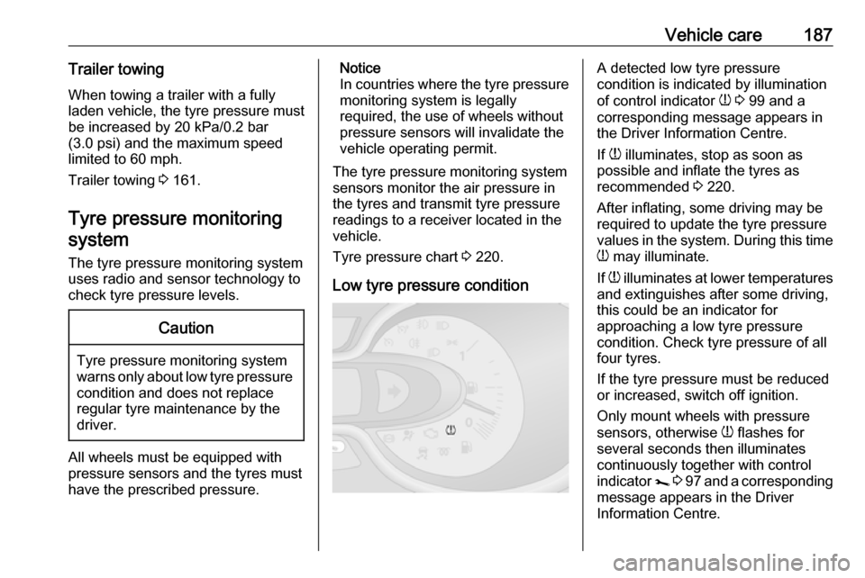
Low tyre pressure conditionA detected low tyre pressure
condition is indicated by illumination
of control indicator w 3 99 and a
corresponding message appears in
the Driver Information Centre.
If w illuminates, stop as soon as
possible and inflate the tyres as
recommended 3 220.
After inflating, some driving may be
required to update the tyre pressure
values in the system. During this time
w may illuminate.
If w illuminates at lower temperatures
and extinguishes after some driving,
this could be an indicator for
approaching a low tyre pressure
condition. Check tyre pressure of all
four tyres.
If the tyre pressure must be reduced
or increased, switch off ignition.
Only mount wheels with pressure
sensors, otherwise w flashes for
several seconds then illuminates
continuously together with control
indicator j 3 97 and a corresponding
message appears in the Driver
Information Centre.