change wheel VAUXHALL VIVARO 2018 Owner's Manual
[x] Cancel search | Manufacturer: VAUXHALL, Model Year: 2018, Model line: VIVARO, Model: VAUXHALL VIVARO 2018Pages: 233, PDF Size: 5.73 MB
Page 13 of 233

In brief111Side air vents ...................... 125
2 Ashtray .................................. 88
Cupholder ............................ 73
3 Light switch ........................ 106
Rear fog light ....................... 110
Front fog lights ...................109
Exit lighting .......................... 112
Turn and lane-change
signals ................................. 109
Sidelights ............................ 106
Headlight flash, low beam
and high beam ....................107
4 Instruments .......................... 89
Driver Information Centre .... 100
Trip computer .....................103
5 Horn ...................................... 83
Driver airbag ......................... 616Windscreen wiper,
windscreen washer system ..84
Rear window wiper, rear
window washer system ........85
Trip computer .....................103
7 Card reader for electronic
key system ............................ 22
8 Steering column controls ......83
9 Centre air vents ................... 125
10 Power outlet .......................... 86
Cigarette lighter ..................... 88
Coin tray, USB slot ................ 71
11 Info display .......................... 100
12 Front passenger airbag .........61
13 Glovebox .............................. 72
14 Heated exterior mirrors .........40
Heated rear window ..............43
Idle speed control ...............133
15 Power outlet .......................... 86
Cigarette lighter ..................... 8816 Climate control system ........ 114
Electronic climate control
system ................................. 116
17 Ashtray .................................. 88
Cupholder ............................ 73
18 Hazard warning flashers .....109
Central locking system ..........24
19 Power button for electronic
key system .......................... 130
20 Eco button for fuel
economy mode ...................128
21 Stop-start system ................134
Cruise control and speed
limiter ................................. 150
22 Remote control on
steering wheel ......................83
Cruise control .....................150
23 Ignition switch with
steering wheel lock .............130
24 Steering wheel adjustment ...83
25 Bonnet release lever ...........164
26 Fuse box ............................. 180
Page 111 of 233
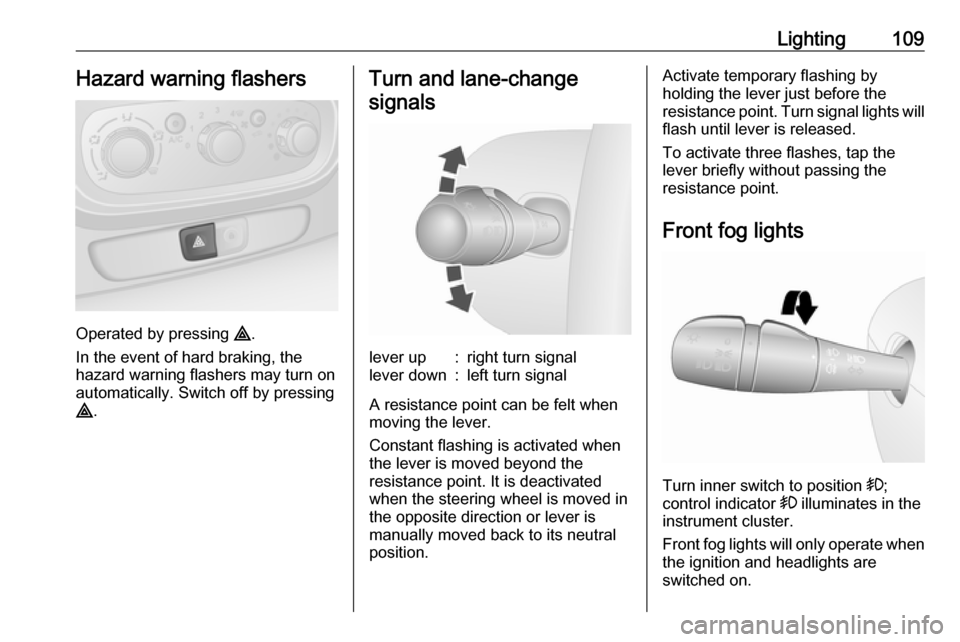
Lighting109Hazard warning flashers
Operated by pressing ¨.
In the event of hard braking, the
hazard warning flashers may turn on automatically. Switch off by pressing
¨ .
Turn and lane-change
signalslever up:right turn signallever down:left turn signal
A resistance point can be felt when
moving the lever.
Constant flashing is activated when
the lever is moved beyond the
resistance point. It is deactivated
when the steering wheel is moved in
the opposite direction or lever is
manually moved back to its neutral
position.
Activate temporary flashing by
holding the lever just before the
resistance point. Turn signal lights will
flash until lever is released.
To activate three flashes, tap the
lever briefly without passing the
resistance point.
Front fog lights
Turn inner switch to position >
;
control indicator > illuminates in the
instrument cluster.
Front fog lights will only operate when
the ignition and headlights are
switched on.
Page 159 of 233
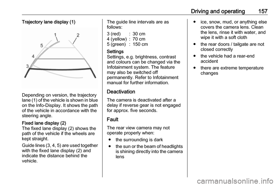
Driving and operating157Trajectory lane display (1)
Depending on version, the trajectory
lane (1) of the vehicle is shown in blue
on the Info-Display. It shows the path of the vehicle in accordance with the
steering angle.
Fixed lane display (2)
The fixed lane display (2) shows the
path of the vehicle if the wheels are
kept straight.
Guide lines (3, 4, 5) are used together
with the fixed lane display (2) and
indicate the distance behind the
vehicle.The guide line intervals are as
follows:3 (red):30 cm4 (yellow):70 cm5 (green):150 cmSettings
Settings, e.g. brightness, contrast
and colours can be changed via the
Infotainment system. The feature
may also be switched off
permanently. Refer to Infotainment
manual for further information.
Deactivation
The camera is deactivated after a
delay if reverse gear is not engaged
for approx. five seconds.
Fault
The rear view camera may not
operate properly when:
● the surrounding is dark
● the sun or the beam of headlights
is shining directly into the camera lens
● ice, snow, mud, or anything else covers the camera lens. Clean
the lens, rinse it with water, and
wipe it with a soft cloth
● the rear doors / tailgate are not closed correctly
● the vehicle had a rear-end accident
● there are extreme temperature changes
Page 185 of 233
Vehicle care183No.Circuit40Rear power outlet41Starting / Body control module42Heated seats43Tachograph44Windscreen wiper45Heating / Air conditioning
After having changed defective fuses,
replace the trim panel.
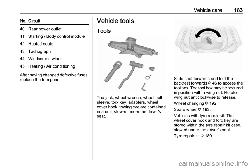
Vehicle tools
Tools
The jack, wheel wrench, wheel bolt
sleeve, torx key, adapters, wheel
cover hook, towing eye are contained
in a unit, stowed under the driver's
seat.
Slide seat forwards and fold the
backrest forwards 3 46 to access the
tool box. The tool box may be secured
in position with a wing nut. Rotate
wing nut anticlockwise to release.
Wheel changing 3 192.
Spare wheel 3 193.
Vehicles with tyre repair kit: The wheel cover hook and torx key are
stored within the tyre repair kit case,
stowed under the driver's seat.
Tyre repair kit 3 189.
Page 194 of 233
192Vehicle careNotice
The driving characteristics of the repaired tyre is severely affected,
therefore have this tyre replaced.
If unusual noise is heard or the
compressor becomes hot, turn
compressor off for at least
30 minutes.
Pay attention to storage information
and expiry date on sealant bottle. Its
sealing capability is not guaranteed
after this time.
Replace the used sealant bottle. Dispose of the sealant bottle as
prescribed by applicable laws.
Wheel changing
Some vehicles are equipped with a
tyre repair kit instead of a spare wheel
3 189.
Make the following preparations and
observe the following information:
● Park the vehicle on a level, firm and non-slippery surface. The
front wheels must be in the
straight-ahead position.
● Apply the parking brake and engage first gear or reverse gear.● Remove the spare wheel 3 193.
● Never change more than one wheel at a time.
● Use the jack only to change wheels in case of puncture, not
for a seasonal winter or summer
tyre change.
● The jack is maintenance-free. ● If the ground on which the vehicle
is standing is soft, a solid board
(max. 1 cm thick) should be
placed under the jack.
● Remove heavy objects out of the
vehicle before jacking up.
● No people or animals may be in the vehicle when it is jacked-up.
● Never crawl under a jacked-up vehicle.
● Do not start the engine when the vehicle is raised on the jack.
● Clean wheel bolts / nuts and thread with a clean cloth before
mounting the wheel.9 Warning
Do not grease wheel bolt, wheel
nut and wheel nut cone.
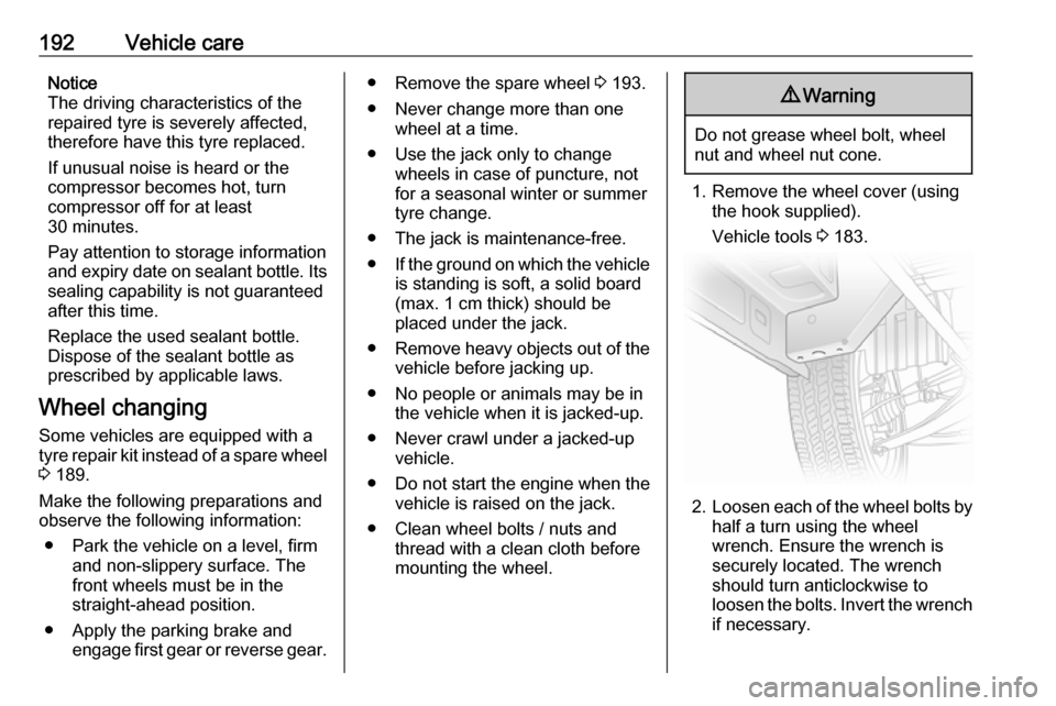
1. Remove the wheel cover (using the hook supplied).
Vehicle tools 3 183.
2. Loosen each of the wheel bolts by
half a turn using the wheel
wrench. Ensure the wrench is
securely located. The wrench
should turn anticlockwise to
loosen the bolts. Invert the wrench if necessary.
Page 195 of 233
Vehicle care193
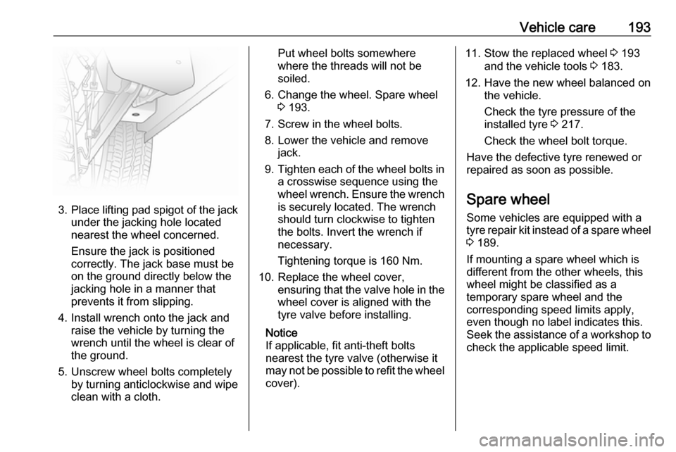
3.Place lifting pad spigot of the jack
under the jacking hole located
nearest the wheel concerned.
Ensure the jack is positioned
correctly. The jack base must be
on the ground directly below the
jacking hole in a manner that
prevents it from slipping.
4. Install wrench onto the jack and raise the vehicle by turning the
wrench until the wheel is clear of
the ground.
5. Unscrew wheel bolts completely by turning anticlockwise and wipe
clean with a cloth.
Put wheel bolts somewhere
where the threads will not be
soiled.
6. Change the wheel. Spare wheel 3 193.
7. Screw in the wheel bolts.
8. Lower the vehicle and remove jack.
9. Tighten each of the wheel bolts in
a crosswise sequence using the
wheel wrench. Ensure the wrench is securely located. The wrench
should turn clockwise to tighten
the bolts. Invert the wrench if
necessary.
Tightening torque is 160 Nm.
10. Replace the wheel cover, ensuring that the valve hole in thewheel cover is aligned with the
tyre valve before installing.
Notice
If applicable, fit anti-theft bolts
nearest the tyre valve (otherwise it
may not be possible to refit the wheel
cover).11. Stow the replaced wheel 3 193
and the vehicle tools 3 183.
12. Have the new wheel balanced on the vehicle.
Check the tyre pressure of the
installed tyre 3 217.
Check the wheel bolt torque.
Have the defective tyre renewed or
repaired as soon as possible.
Spare wheel
Some vehicles are equipped with a tyre repair kit instead of a spare wheel
3 189.
If mounting a spare wheel which is
different from the other wheels, this
wheel might be classified as a
temporary spare wheel and the
corresponding speed limits apply,
even though no label indicates this.
Seek the assistance of a workshop to
check the applicable speed limit.
Page 230 of 233

228Rear view camera ...................... 155
Rear windows .............................. 42
Rear window wiper/washer .......... 85
Recommended fluids and lubricants ........................ 202, 206
Refuelling ................................... 158 Registered trademarks ...............222
Remote control ............................. 20
Restraining lattice .........................79
Reversing light ........................... 176
Reversing lights .........................110
Ride control systems ..................147
Roof load ...................................... 80
Roof rack ..................................... 80
S Safety belts ................................... 53
Safety net .................................... 78
Seat adjustment ....................... 7, 46
Seat belt ........................................ 8
Seat belt reminder .......................95
Seat belts ..................................... 53
Seat folding .................................. 48
Seat heating ................................. 48
Seat position ................................ 45
Seats ............................................ 74
Selective catalytic reduction .......139
Service ............................... 127, 201
Service display ............................ 91
Service information ....................201Service vehicle soon .................... 96
Side airbag system ......................61
Sidelights .................................... 106
Side turn signal lights ................175
Sliding door .................................. 31
Sliding side door ........................... 31
Spare wheel ............................... 193
Spare wheel security tool ...........183
Speed limiter......................... 89, 153
Speedometer ............................... 89
Starting and operating ................130
Starting off ................................... 17
Starting the engine ...............17, 132
Steering ...................................... 129
Steering column controls ..............83
Steering wheel adjustment ......9, 83
Steering wheel controls ...............83
Stop engine .................................. 96
Stop-start system............ 17, 99, 134
Storage ......................................... 71
Storage box .................................. 74
Storage compartment ...................73
Storage compartments .................71
Sun visors .................................... 43
Symbols ......................................... 4
T
Tablet holder................................. 71
Tachograph ........................ 100, 105
Tachometer ................................. 90Tailgate......................................... 33
Tailgate emergency release .........33
Tail lights ................................... 174
Technical data ............................ 207
Temporary spare wheel ..............193
Three-point seat belt .................... 54
Toll road stickers .......................... 41
Tools .......................................... 183
Top-Tether .................................... 63
Torx key ...................................... 183
Touchscreen ............................... 100
Tow bar....................................... 160
Towing ................................ 160, 196
Towing another vehicle .............197
Towing a trailer ........................... 161
Towing eye ......................... 183, 196
Towing the vehicle .....................196
Traction Control system ............. 147
Trailer coupling ........................... 160
Trailer stability assist .................161
Trailer towing ............................. 161
Transmission ............................... 16
Tread depth ............................... 188
Trip computer ............................ 103
Trip odometer .............................. 89
Turbo engine warm-up ...............132
Turn and lane-change signals ...109
Turn signal ................................... 94
Tyre chains ................................ 189
Tyre changing ............................. 192