ECU VAUXHALL VIVARO 2019 Owner's Guide
[x] Cancel search | Manufacturer: VAUXHALL, Model Year: 2019, Model line: VIVARO, Model: VAUXHALL VIVARO 2019Pages: 231, PDF Size: 5.82 MB
Page 127 of 231

Climate control125Open the cover and replace the
battery (Type A: CR 2430, Type B:
2CR 11108, or equivalent), ensuring
the new battery is correctly installed
with the positive ( <) side facing the
positive terminals. Replace the cover securely.
Dispose of old batteries in
accordance with environmental
regulations.
Batteries do not belong in household
waste. They must be disposed of at
an appropriate recycling collection
point.
Operation (Type A)
Heating Y
Select Y in the menu bar and press
G to confirm. The predetermined
heating duration, e.g. L 30, flashes in
the display. The factory setting is 30 minutes.
Adjust the heating duration using k
or l and confirm. The value can be
set from ten to 120 minutes. Due to
the power consumption, note the
heating duration.
To switch off, select Y in the menu bar
again and press d.
Programming P
Up to three preset departure times
can be programmed, either during
one day or over one week.
● Select P in the menu bar and
press G to confirm.
● Select desired preset memory number P1, P2 or P3 and
confirm.
● Select F and confirm.
● Select weekday or weekday group and confirm.
● Select hour and confirm.
● Select minutes and confirm.
● Select Y and confirm.
● Select ECO or HIGH and confirm.
● Select duration and confirm.
● Press d to exit.Repeat the procedure to programme
the other preset memory numbers if
required.
To activate a desired preset memory
number select P1, P2 or P3, then
select On and confirm.
When a program is activated P and
Y will be displayed together.
To deactivate a preset memory,
select P1, P2 or P3, then select Off
and confirm.
Heating stops automatically
5 minutes after the programmed
departure time.
Notice
The remote control system features a temperature sensor which
calculates the runtime according to the ambient temperature and thedesired heating level (ECO or
HIGH). The system starts
automatically between five and
60 minutes prior to the programmed
departure time.
Set time and weekday Þ
If the vehicle battery is disconnected or its voltage is too low, the unit will
need to be reset.
Page 170 of 231
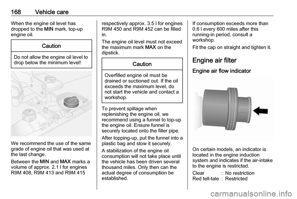
168Vehicle careWhen the engine oil level has
dropped to the MIN mark, top-up
engine oil.Caution
Do not allow the engine oil level to drop below the minimum level!
We recommend the use of the same
grade of engine oil that was used at
the last change.
Between the MIN and MAX marks a
volume of approx. 2.1 l for engines R9M 408, R9M 413 and R9M 415
respectively approx. 3.5 l for engines
R9M 450 and R9M 452 can be filled
in.
The engine oil level must not exceed the maximum mark MAX on the
dipstick.Caution
Overfilled engine oil must be
drained or suctioned out. If the oil
exceeds the maximum level, do
not start the vehicle and contact a
workshop.
To prevent spillage when
replenishing the engine oil, we
recommend using a funnel to top-up the engine oil. Ensure funnel is
securely located onto the filler pipe.
After topping-up, put the funnel into a
plastic bag and stow it securely.
A stabilization of the engine oil
consumption will not take place until
the vehicle has been driven several
thousand miles. Only then can the
actual degree of consumption be
established.
If consumption exceeds more than
0.6 l every 600 miles after this
running-in period, consult a
workshop.
Fit the cap on straight and tighten it.
Engine air filter
Engine air flow indicator
On certain models, an indicator is
located in the engine induction
system and indicates if the air-intake
to the engine is restricted.
Clear:No restrictionRed tell-tale:Restricted
Page 176 of 231
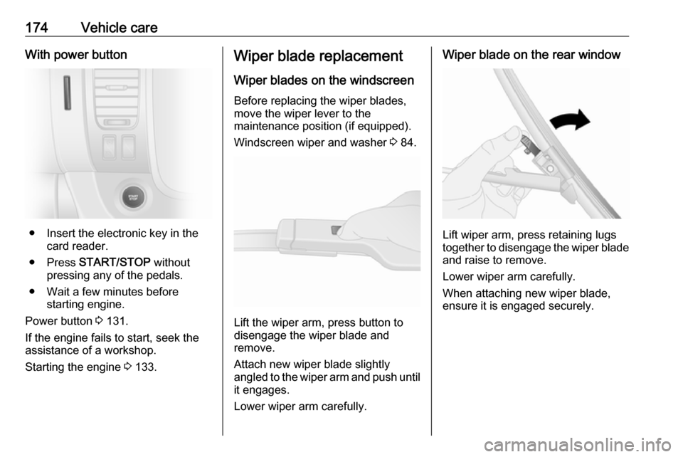
174Vehicle careWith power button
● Insert the electronic key in thecard reader.
● Press START/STOP without
pressing any of the pedals.
● Wait a few minutes before starting engine.
Power button 3 131.
If the engine fails to start, seek the
assistance of a workshop.
Starting the engine 3 133.
Wiper blade replacement
Wiper blades on the windscreen
Before replacing the wiper blades,
move the wiper lever to the
maintenance position (if equipped).
Windscreen wiper and washer 3 84.
Lift the wiper arm, press button to
disengage the wiper blade and
remove.
Attach new wiper blade slightly
angled to the wiper arm and push until
it engages.
Lower wiper arm carefully.
Wiper blade on the rear window
Lift wiper arm, press retaining lugs
together to disengage the wiper blade
and raise to remove.
Lower wiper arm carefully.
When attaching new wiper blade,
ensure it is engaged securely.
Page 179 of 231
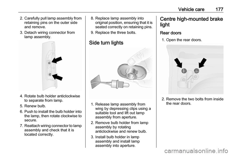
Vehicle care1772.Carefully pull lamp assembly from
retaining pins on the outer side
and remove.
3. Detach wiring connector from lamp assembly.
4. Rotate bulb holder anticlockwiseto separate from lamp.
5. Renew bulb.
6. Push to install the bulb holder into
the lamp, then rotate clockwise to secure.
7. Reattach wiring connector to lamp
assembly and check that it is
located correctly.
8. Replace lamp assembly into original position, ensuring that it isseated correctly on retaining pins.
9. Replace the three bolts.
Side turn lights
1. Release lamp assembly from wing by depressing clips using a
suitable tool and lift out lamp
assembly from aperture.
2. Remove bulb holder from lamp assembly by rotating
anticlockwise and renew bulb.
3. Install bulb holder in lamp assembly and install lamp
assembly into aperture.
Centre high-mounted brake
light
Rear doors 1. Open the rear doors.
2. Remove the two bolts from inside the rear doors.
Page 181 of 231
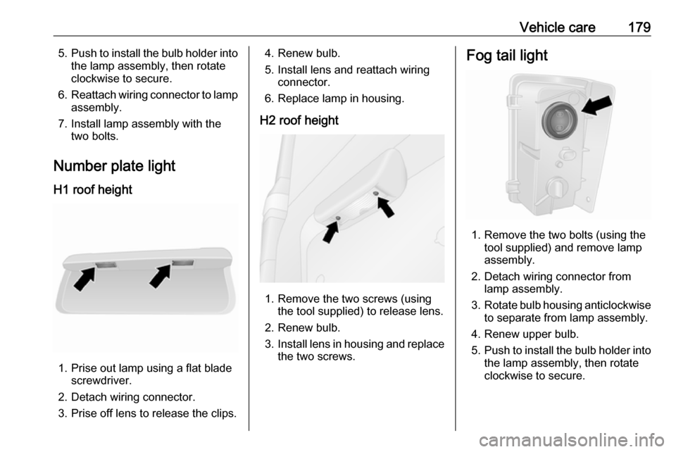
Vehicle care1795.Push to install the bulb holder into
the lamp assembly, then rotate
clockwise to secure.
6. Reattach wiring connector to lamp
assembly.
7. Install lamp assembly with the two bolts.
Number plate light
H1 roof height
1. Prise out lamp using a flat blade screwdriver.
2. Detach wiring connector.
3. Prise off lens to release the clips.
4. Renew bulb.
5. Install lens and reattach wiring connector.
6. Replace lamp in housing.
H2 roof height
1. Remove the two screws (using the tool supplied) to release lens.
2. Renew bulb.
3. Install lens in housing and replace
the two screws.
Fog tail light
1. Remove the two bolts (using the tool supplied) and remove lamp
assembly.
2. Detach wiring connector from lamp assembly.
3. Rotate bulb housing anticlockwise
to separate from lamp assembly.
4. Renew upper bulb.
5. Push to install the bulb holder into
the lamp assembly, then rotate
clockwise to secure.
Page 187 of 231
Vehicle care185No.Circuit40Rear power outlet41Starting / Body control module42Heated seats43Tachograph44Windscreen wiper45Heating / Air conditioning
After having changed defective fuses,
replace the trim panel.
Vehicle tools
Tools
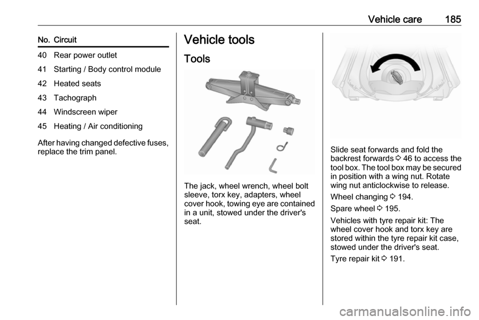
The jack, wheel wrench, wheel bolt
sleeve, torx key, adapters, wheel
cover hook, towing eye are contained
in a unit, stowed under the driver's
seat.
Slide seat forwards and fold the
backrest forwards 3 46 to access the
tool box. The tool box may be secured
in position with a wing nut. Rotate
wing nut anticlockwise to release.
Wheel changing 3 194.
Spare wheel 3 195.
Vehicles with tyre repair kit: The wheel cover hook and torx key are
stored within the tyre repair kit case,
stowed under the driver's seat.
Tyre repair kit 3 191.
Page 196 of 231
194Vehicle careWheel changingSome vehicles are equipped with a
tyre repair kit instead of a spare wheel
3 191.
Make the following preparations and
observe the following information:
● Park the vehicle on a level, firm and non-slippery surface. The
front wheels must be in the
straight-ahead position.
● Apply the parking brake and engage first gear or reverse gear.
● Remove the spare wheel 3 195.
● Never change more than one wheel at a time.
● Use the jack only to change wheels in case of puncture, not
for a seasonal winter or summer
tyre change.
● The jack is maintenance-free.
● If the ground on which the vehicle
is standing is soft, a solid board
(max. 1 cm thick) should be
placed under the jack.
● Remove heavy objects out of the
vehicle before jacking up.● No people or animals may be in the vehicle when it is jacked-up.
● Never crawl under a jacked-up vehicle.
● Do not start the engine when the vehicle is raised on the jack.
● Clean wheel bolts / nuts and thread with a clean cloth before
mounting the wheel.9 Warning
Do not grease wheel bolt, wheel
nut and wheel nut cone.
1. Remove the wheel cover (using the hook supplied).
Vehicle tools 3 185.
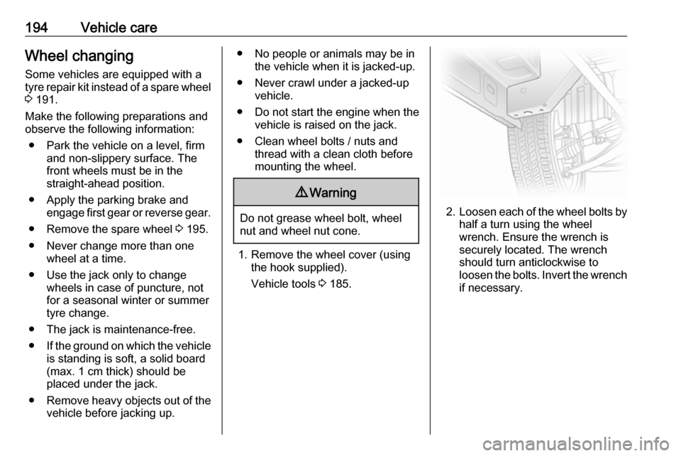
2. Loosen each of the wheel bolts by
half a turn using the wheel
wrench. Ensure the wrench is
securely located. The wrench
should turn anticlockwise to
loosen the bolts. Invert the wrench if necessary.
Page 197 of 231
Vehicle care195
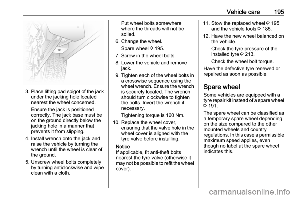
3.Place lifting pad spigot of the jack
under the jacking hole located
nearest the wheel concerned.
Ensure the jack is positioned
correctly. The jack base must be
on the ground directly below the
jacking hole in a manner that
prevents it from slipping.
4. Install wrench onto the jack and raise the vehicle by turning the
wrench until the wheel is clear of
the ground.
5. Unscrew wheel bolts completely by turning anticlockwise and wipe
clean with a cloth.
Put wheel bolts somewhere
where the threads will not be
soiled.
6. Change the wheel. Spare wheel 3 195.
7. Screw in the wheel bolts.
8. Lower the vehicle and remove jack.
9. Tighten each of the wheel bolts in
a crosswise sequence using the
wheel wrench. Ensure the wrench is securely located. The wrench
should turn clockwise to tighten
the bolts. Invert the wrench if
necessary.
Tightening torque is 160 Nm.
10. Replace the wheel cover, ensuring that the valve hole in thewheel cover is aligned with the
tyre valve before installing.
Notice
If applicable, fit anti-theft bolts
nearest the tyre valve (otherwise it
may not be possible to refit the wheel
cover).11. Stow the replaced wheel 3 195
and the vehicle tools 3 185.
12. Have the new wheel balanced on the vehicle.
Check the tyre pressure of the
installed tyre 3 213.
Check the wheel bolt torque.
Have the defective tyre renewed or
repaired as soon as possible.
Spare wheel
Some vehicles are equipped with a tyre repair kit instead of a spare wheel
3 191.
The spare wheel can be classified as
a temporary spare wheel depending
on the size compared to the other
mounted wheels and country
regulations. In this case a permissible maximum speed applies, even
though no label at the spare wheel
indicates this.
Page 198 of 231
196Vehicle careCaution
The use of a spare wheel that issmaller than the other wheels or in combination with winter tyres
could affect driveability. Have the defective tyre replaced as soon as
possible.
It may be necessary to jack the
vehicle up to gain access to the spare
wheel on a fully loaded vehicle with a
flat rear tyre.
Wheel changing 3 194.
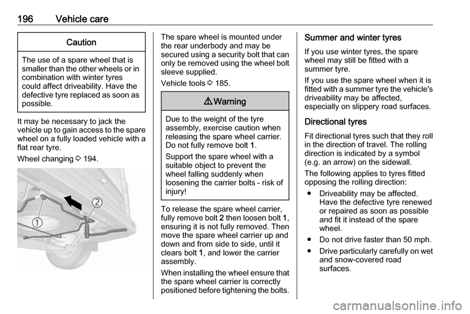
The spare wheel is mounted under
the rear underbody and may be
secured using a security bolt that can
only be removed using the wheel bolt sleeve supplied.
Vehicle tools 3 185.9 Warning
Due to the weight of the tyre
assembly, exercise caution when
releasing the spare wheel carrier.
Do not fully remove bolt 1.
Support the spare wheel with a
suitable object to prevent the
wheel falling suddenly when
loosening the carrier bolts - risk of injury!
To release the spare wheel carrier,fully remove bolt 2 then loosen bolt 1,
ensuring it is not fully removed. Then
move the spare wheel carrier up and
down and from side to side, until it
clears bolt 1, and lower the carrier
assembly.
When installing the wheel ensure that
the spare wheel carrier is correctly
positioned before tightening the bolts.
Summer and winter tyres
If you use winter tyres, the spare
wheel may still be fitted with a
summer tyre.
If you use the spare wheel when it is
fitted with a summer tyre the vehicle's driveability may be affected,
especially on slippery road surfaces.
Directional tyres
Fit directional tyres such that they roll in the direction of travel. The rolling
direction is indicated by a symbol
(e.g. an arrow) on the sidewall.
The following applies to tyres fitted
opposing the rolling direction:
● Driveability may be affected. Have the defective tyre renewed
or repaired as soon as possible
and fit it instead of the spare
wheel.
● Do not drive faster than 50 mph.
● Drive particularly carefully on wet
and snow-covered road
surfaces.
Page 224 of 231

222IndexAAbsorptive Glass Mat battery .....171
Accessories and vehicle modifications .......................... 165
AdBlue .................. 99, 104, 140, 204
AdBlue tank ................................ 212
Adjustable air vents ...................127
AGM battery ............................... 171
Airbag and belt tensioners ...........96
Airbag deactivation ................62, 96
Airbag label............................. 58, 62
Airbag system .............................. 58
Air conditioning regular operation ................................ 128
Air conditioning system .............. 117
Air intake .................................... 128
Air recirculation ...................117, 198
Air vents...................................... 127
Alert ............................................ 103
Antifreeze ................................... 169
Antilock brake system ................ 146
Antilock brake system (ABS) .......98
Anti-theft alarm system ................36
Anti-theft bolts............................. 194
Anti-theft locking system .............. 35
Anti-theft security lock ..................24
Appearance care ........................200
Armrest ........................................ 48
Ashtrays ....................................... 88 Automatic anti-dazzle ..................41Automatic fuel cut-off ..................134
Automatic light control ...............109
Automatic locking ........................30
Autostop ............................. 133, 135
Auxiliary heater ........................... 122
B Battery .................... 20, 21, 122, 171
Battery discharge protection ......115
Battery, jump starting.................. 197
Belts.............................................. 53 Bench seat.................................... 74
Bonnet ....................................... 166
Bottle holders................................ 74 Brake and clutch fluid .................204
Brake assist ............................... 147
Brake fluid .................................. 170
Brakes ............................... 146, 170
Brake system ............................... 97
Breakdown.................................. 198
Bulb replacement ....................... 175
C Capacities .................................. 212
Car Pass ...................................... 20
Catalytic converter .....................139
Central locking system ................24
Centre high-mounted brake light 177
Changing tyre and wheel size ...190
Charging system .......................... 97
Child locks ................................... 30