Battery VAUXHALL VIVARO C 2020 Owner's Guide
[x] Cancel search | Manufacturer: VAUXHALL, Model Year: 2020, Model line: VIVARO C, Model: VAUXHALL VIVARO C 2020Pages: 289, PDF Size: 10.16 MB
Page 219 of 289
Vehicle care217When the vehicle battery is being
replaced, please ensure that there
are no open ventilation holes in the
vicinity of the positive terminal. If a
ventilation hole is open in this area, it
must be closed off with a dummy cap,
and the ventilation in the vicinity of the negative terminal must be opened.
Ensure that the battery is always replaced by the same type of battery.
The vehicle battery has to be
replaced by a workshop.
Stop-start system 3 156.
Charging the vehicle battery9 Warning
On vehicles with stop-start
system, ensure that the charging potential does not exceed 14.6 V
when using a battery charger.
Otherwise the vehicle battery may be damaged.
Jump starting 3 249.
Discharge protection
Battery voltage
When the vehicle battery voltage is
running low, a warning message will
appear in the Driver Information
Centre.
When the vehicle is being driven, the
load reduction function temporarily
deactivates certain functions, such as
the air conditioning, the heated rear
window, heated steering wheel, etc.
The deactivated functions are
reactivated automatically as soon as
conditions permit.
Idle boost
If charging of the vehicle battery is
required due to battery condition, the
power output of the generator must
be increased. This will be achieved by
an idle boost which may be audible.
A message appears in the Driver
Information Centre.
Power outlet
The power outlets are deactivated in
the event of low vehicle battery
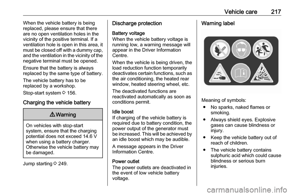
voltage.Warning label
Meaning of symbols:
● No sparks, naked flames or smoking.
● Always shield eyes. Explosive gases can cause blindness or
injury.
● Keep the vehicle battery out of reach of children.
● The vehicle battery contains sulphuric acid which could cause
blindness or serious burn
injuries.
Page 220 of 289

218Vehicle care● See the Owner's Manual forfurther information.
● Explosive gas may be present in the vicinity of the vehicle battery.
Heating functionalities Notice
Individual heating functionalities,
such as heated seats or heated
steering wheel, may be temporarily
unavailable in the event of electrical
loading constraints. Functions will
be resumed after some minutes.
Power saving mode
This mode deactivates electrical
consumers to avoid excessive
discharging of the vehicle battery.
These consumers, such as the
Infotainment system, windscreen
wipers, low beam headlights,
courtesy light, etc. can be used for a
total maximum time of about
40 minutes after ignition is switched
off.Deactivating power saving mode
Power saving mode is deactivated
automatically when the engine is
restarted. Run the engine for a
sufficient charge:
● for less than 10 minutes to use the consumers for approx.
5 minutes
● for more than 10 minutes to use the consumers for up to approx.
30 minutes
Diesel fuel system bleeding If the tank has been run dry, the diesel fuel system must be bled. The
bleeding procedure differs between
the engine types 3 268. Fuel up with
at least five litres of diesel before
starting the bleeding procedure.
Engines DV5RUCd, DV5RUC 1. Switch on the ignition.
2. Wait 1 minute and switch off the
ignition.
3. Try to start the engine.
If the engine does not start after a
short time, repeat the procedure.Engines DW10FEU, DW10FD,
DW10FDCU, DW10F
1. Switch on the ignition.
2. Wait 6 seconds and switch off the ignition.
3. Repeat steps 1 and 2 for ten times.
4. Try to start the engine.
If the engine does not start after a
short time, repeat the procedure.
Engine DV6DU1. Open the engine bonnet.
2. If necessary, unclip the engine
style cover to access the priming
pump.
3. Operate the priming pump
repeatedly until resistance is felt
(there may be resistance at the first
press).
4. Try to start the engine. If the engine
does not start after a short time, wait
around 15 seconds before trying
again. If the engine does not start
after a few attempts, repeat step 3
and try again to start the engine.
5. Put the engine style cover in place
and clip it in.
Page 234 of 289
232Vehicle care
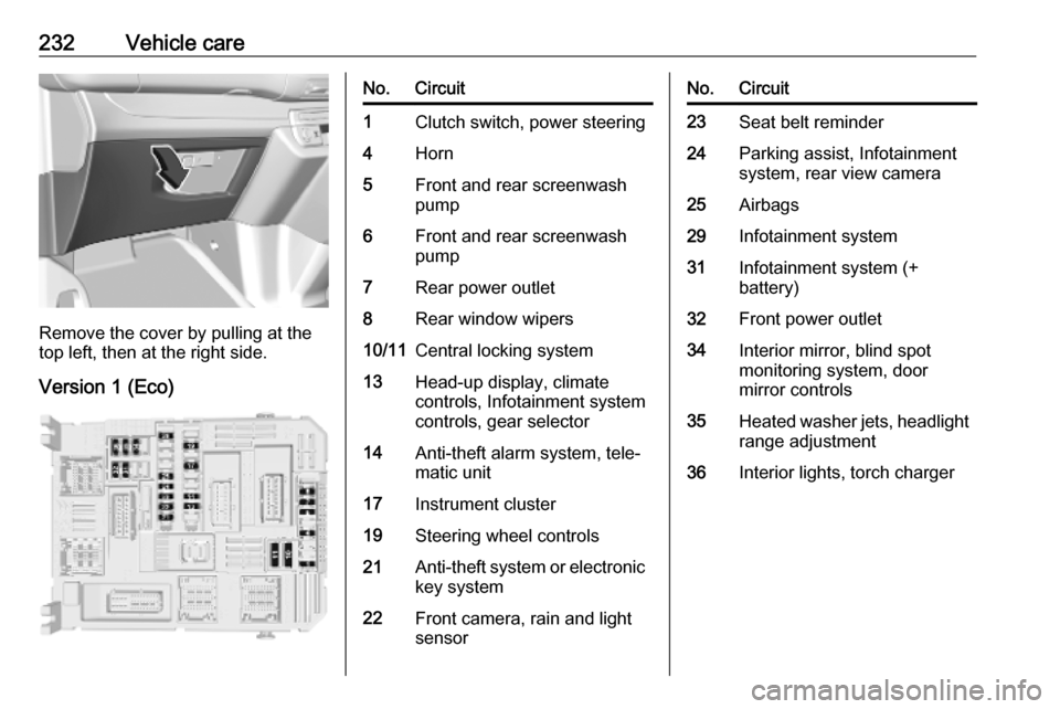
Remove the cover by pulling at the
top left, then at the right side.
Version 1 (Eco)
No.Circuit1Clutch switch, power steering4Horn5Front and rear screenwash
pump6Front and rear screenwash
pump7Rear power outlet8Rear window wipers10/11Central locking system13Head-up display, climate
controls, Infotainment system
controls, gear selector14Anti-theft alarm system, tele‐
matic unit17Instrument cluster19Steering wheel controls21Anti-theft system or electronic key system22Front camera, rain and light
sensorNo.Circuit23Seat belt reminder24Parking assist, Infotainment
system, rear view camera25Airbags29Infotainment system31Infotainment system (+
battery)32Front power outlet34Interior mirror, blind spot
monitoring system, door
mirror controls35Heated washer jets, headlight
range adjustment36Interior lights, torch charger
Page 235 of 289
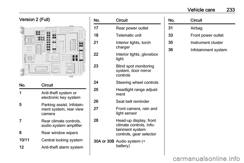
Vehicle care233Version 2 (Full)No.Circuit1Anti-theft system or
electronic key system5Parking assist, Infotain‐
ment system, rear view
camera7Rear climate controls,
audio system amplifier8Rear window wipers10/11Central locking system12Anti-theft alarm systemNo.Circuit17Rear power outlet18Telematic unit21Interior lights, torch
charger22Interior lights, glovebox
light23Blind spot monitoring
system, door mirror
controls24Steering wheel controls25Headlight range adjust‐
ment26Seat belt reminder27Front camera, rain and
light sensor28Head-up display, front
climate controls, Info‐
tainment system
controls, gear selector30A or 30BAudio system (+
battery)No.Circuit31Airbag33Front power outlet35Instrument cluster36Infotainment system
Page 243 of 289
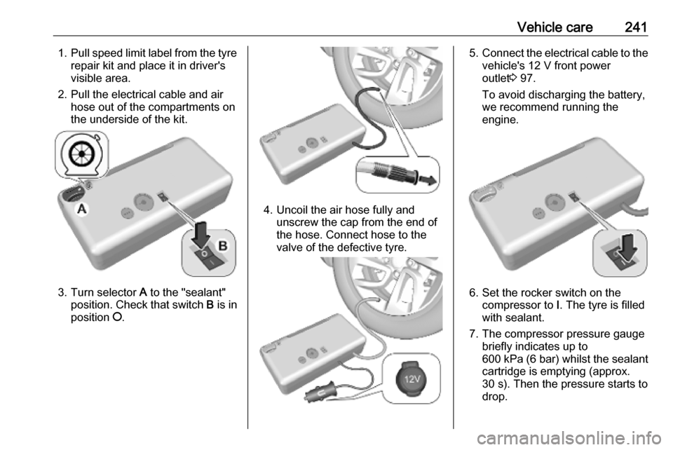
Vehicle care2411.Pull speed limit label from the tyre
repair kit and place it in driver's
visible area.
2. Pull the electrical cable and air hose out of the compartments on
the underside of the kit.
3. Turn selector A to the "sealant"
position. Check that switch B is in
position J.
4. Uncoil the air hose fully and
unscrew the cap from the end of
the hose. Connect hose to the
valve of the defective tyre.
5. Connect the electrical cable to the
vehicle's 12 V front power
outlet 3 97.
To avoid discharging the battery,
we recommend running the
engine.
6. Set the rocker switch on the compressor to I. The tyre is filled
with sealant.
7. The compressor pressure gauge briefly indicates up to
600 kPa (6 bar) whilst the sealant
cartridge is emptying (approx.
30 s). Then the pressure starts to
drop.
Page 251 of 289
Vehicle care249
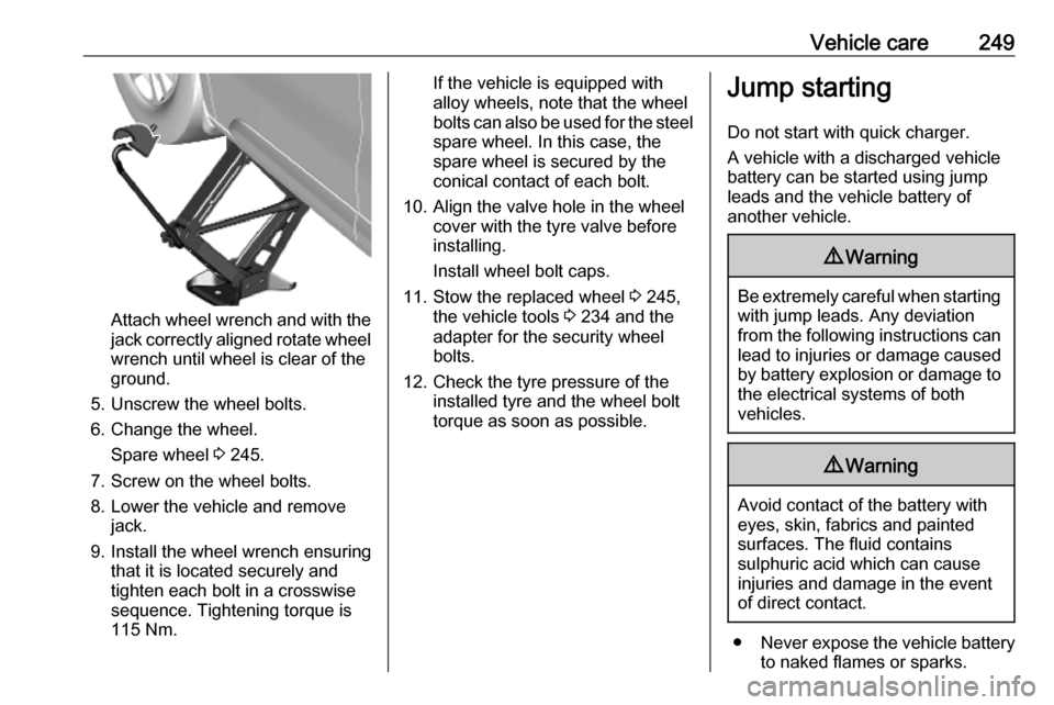
Attach wheel wrench and with the
jack correctly aligned rotate wheel wrench until wheel is clear of the
ground.
5. Unscrew the wheel bolts. 6. Change the wheel. Spare wheel 3 245.
7. Screw on the wheel bolts.
8. Lower the vehicle and remove jack.
9. Install the wheel wrench ensuring that it is located securely and
tighten each bolt in a crosswise
sequence. Tightening torque is
115 Nm.
If the vehicle is equipped with
alloy wheels, note that the wheel
bolts can also be used for the steel spare wheel. In this case, the
spare wheel is secured by the
conical contact of each bolt.
10. Align the valve hole in the wheel cover with the tyre valve before
installing.
Install wheel bolt caps.
11. Stow the replaced wheel 3 245,
the vehicle tools 3 234 and the
adapter for the security wheel bolts.
12. Check the tyre pressure of the installed tyre and the wheel bolttorque as soon as possible.Jump starting
Do not start with quick charger.
A vehicle with a discharged vehicle
battery can be started using jump
leads and the vehicle battery of
another vehicle.9 Warning
Be extremely careful when starting
with jump leads. Any deviation
from the following instructions can
lead to injuries or damage caused
by battery explosion or damage to the electrical systems of both
vehicles.
9 Warning
Avoid contact of the battery with
eyes, skin, fabrics and painted
surfaces. The fluid contains
sulphuric acid which can cause
injuries and damage in the event
of direct contact.
● Never expose the vehicle battery
to naked flames or sparks.
Page 252 of 289

250Vehicle care● A discharged vehicle battery canalready freeze at a temperature
of 0 °C. Defrost the frozen battery before connecting jump leads.
● Wear eye protection and protective clothing when
handling a battery.
● Use a booster battery with the same voltage (12 V). Its capacity
(Ah) must not be much less than
that of the discharged vehicle
battery.
● Use jump leads with insulated terminals and a cross section of
at least 16 mm 2
(25 mm 2
for
diesel engines).
● Do not disconnect the discharged
vehicle battery from the vehicle.
● Switch off all unnecessary electrical consumers.
● Do not lean over the vehicle battery during jump starting.
● Do not allow the terminals of one
lead to touch those of the other
lead.● The vehicles must not come into contact with each other during
the jump starting process.
● Apply the parking brake, transmission in neutral,
automatic transmission in P.
Open the positive terminal protection
caps of both vehicle batteries.
Lead connection order: 1. Connect the red lead to the positive terminal of the booster
battery.
2. Connect the other end of the red lead to the positive terminal of the
discharged battery.
3. Connect the black lead to the negative terminal of the boosterbattery.
4. Connect the other end of the black
lead to a vehicle grounding point
of your vehicle in the engine
compartment.
Route the leads so that they cannot
catch on rotating parts in the engine
compartment.
To start the engine: 1. Start the engine of the vehicle providing the jump.
2. After 5 minutes, start the other engine. Start attempts should be
made for no longer than 15
seconds at an interval of 1 minute.
3. Allow both engines to idle for approx. three minutes with the
leads connected.
4. Switch on electrical consumers e.g. headlights, heated rear
window of the vehicle receiving
the jump start.
5. Reverse above sequence exactly when removing leads.
Page 280 of 289

278Customer informationDepending on technical equipment
level, the data stored is as follows:
● system component operating states (e.g. fill level, tyre
pressure, battery status)
● faults and defects in important system components (e.g. lights,
brakes)
● system reactions in special driving situations (e.g. triggering
of an airbag, actuation of the
stability control systems)
● information on events damaging the vehicle
● for electric vehicles the amount of
charge in the high-voltage
battery, estimated range
In special cases (e.g. if the vehicle
has detected a malfunction), it may be
necessary to save data that would
otherwise just be volatile.
When you use services (e.g. repairs,
maintenance), the operating data
saved can be read together with the
vehicle identification number and
used when necessary. Staff working
for the service network ( e.g. garages,
manufacturers) or third parties (e.g.breakdown services) can read the
data from the vehicle. The same
applies to warranty work and quality
assurance measures.
Data is generally read via the OBD
(On-Board Diagnostics) port
prescribed by law in the vehicle. The operating data which is read out,
documents the technical condition of
the vehicle or individual components
and assists with fault diagnosis,
compliance with warranty obligations
and quality improvement. This data,
in particular information on
component stress, technical events,
operator errors and other faults, is
transmitted to the manufacturer
where appropriate, together with the
vehicle identification number. The
manufacturer is also subject to
product liability. The manufacturer
potentially also uses operating data
from vehicles for product recalls. This
data can also be used to check
customer warranty and guarantee
claims.
Fault memories in the vehicle can be
reset by a service company when
carrying out servicing or repairs or at
your request.Comfort and Infotainment
functions
Comfort settings and custom settingscan be stored in the vehicle and
changed or reset at any time.
Depending on the equipment level in
question, these include
● seat and steering wheel position settings
● chassis and air conditioning settings
● custom settings such as interior lighting
You can input your own data in the
Infotainment functions for your
vehicle as part of the selected
features.
Depending on the equipment level in
question, these include
● multimedia data such as music, videos or photos for playback in
an integrated multimedia system
● address book data for use with an
integrated hands-free system or an integrated navigation system
Page 284 of 289

282IndexAAccessories and vehicle modifications .......................... 211
Active emergency braking ..115, 188
Adaptive cruise control .......114, 179
AdBlue ................................ 113, 161
Adjustable air vents ...................148
Airbag and belt tensioners .........110
Airbag deactivation ..............64, 110
Airbag label................................... 60 Airbag system .............................. 60
Air conditioning regular operation ................................ 150
Air conditioning system .............. 140
Air intake .................................... 149
Air vents...................................... 148
Antilock brake system ................ 168
Antilock brake system (ABS) .....111
Anti-theft alarm system ................36
Anti-theft locking system .............. 35 Appearance care ........................253
Armrest ......................................... 51
Automatic anti-dazzle ..................40
Automatic crash notification (ACN) ...................................... 127
Automatic light control ...............130
Automatic locking ........................28
Automatic transmission .............164
Autostop ............................. 114, 156B
Battery discharge protection ......137
BlueInjection ............................... 161
Bonnet ....................................... 213
Brake and clutch fluid .................262
Brake assist ............................... 169
Brake fluid .................................. 216 Brakes ............................... 168, 216
Brake system ............................. 111
Breakdown.................................. 251
Bulb replacement ....................... 219
C Camera display........................... 199
Capacities .................................. 270
Cargo management system ........81
Catalytic converter .....................160
Central locking system ................24
Centre console lighting ..............136
Centre high-mounted brake light 228
Changing tyre and wheel size ...239
Charging system ........................ 110
child lock ....................................... 42
Child locks ................................... 28
Child restraint installation locations ................................... 69
Child restraints.............................. 66
Child restraint systems ................66
Child surveillance mirror ...............40
Climate control ............................. 15
Page 288 of 289

286Tow bar....................................... 205
Towing ................................ 205, 251
Towing another vehicle .............252
Towing equipment .....................206
Towing the vehicle .....................251
Trailer coupling ........................... 205
Trailer stability assist .................209
Trailer towing ............................. 206
Transmission ............................... 17
Transmission display .................165
Tread depth ............................... 239
Trip odometer ............................ 105
Turn lights .......................... 109, 133
Tyre chains ................................ 240
Tyre deflation detection system . 238
Tyre designations ......................236
Tyre pressure ............................ 237
Tyre pressures ........................... 271
Tyre repair kit ............................. 240
U Ultrasonic parking assist............. 191
Underseat storage .......................79
Upholstery .................................. 255
USB port ....................................... 97
Using this manual ..........................3
V
Valet mode ................................. 119
Vauxhall Connect .......................127
Vehicle battery ........................... 216Vehicle checks............................ 212
Vehicle data ................................ 266
Vehicle data recording and privacy ..................................... 277
Vehicle detected ahead ..............114
Vehicle dimensions .................... 270
Vehicle Identification Number ....264
Vehicle jack ................................ 234
Vehicle locator lighting ...............137
Vehicle messages .....................122
Vehicle personalisation .............123
Vehicle security ............................ 35
Vehicle specific data ......................3
Vehicle storage ........................... 211
Vehicle tools ............................... 234
Vehicle unlocking ........................... 6 Ventilation ................................... 146
W Warning chimes .........................122
Warning lights ............................. 104
Washer and wiper systems .........13
Washer fluid ............................... 215
Wheel changing .........................244
Wheel covers ............................. 240
Wheels and tyres .......................236
Windows ....................................... 41
Windscreen................................... 41
Windscreen wiper and washer ....94Winter tyres ............................... 236
Wiper blade replacement ..........219
X Xenon headlights .......................223