Side light VAUXHALL VIVARO C 2020 Owner's Guide
[x] Cancel search | Manufacturer: VAUXHALL, Model Year: 2020, Model line: VIVARO C, Model: VAUXHALL VIVARO C 2020Pages: 289, PDF Size: 10.16 MB
Page 191 of 289

Driving and operating189FunctionalityActive emergency braking is
equipped with a front camera and
operates in forward gear above
walking speed up to 53 mph. The
system detects stationary vehicles
only if the speed does not exceed
50 mph. Pedestrians are detected
only if the speed does not exceed
37 mph.
A precondition is that active
emergency braking is not deactivated
in the vehicle personalisation menu
3 123.
If deactivated, m illuminates in the
instrument cluster and a warning
message is displayed in the Driver
Information Centre.
If the system has been deactivated, it
is reactivated automatically the next
time the ignition is switched on.
The system includes: ● emergency automatic braking
● forward collision alert
● front pedestrian protectionEmergency automatic braking
After activation of brake preparation
system and just before the imminent
collision, this function automatically
applies limited braking to reduce the
impact speed of the collision or
prohibit a crash.
If active emergency braking is
applied, m flashes in the instrument
cluster.
Depending on the situation, the
vehicle may automatically brake
moderately or hard.
Front automatic braking can only
occur if a vehicle or a pedestrian
ahead is detected.
Forward collision alert 3 186
Front pedestrian protection 3 190
Below a speed of 19 mph, emergency automatic braking may slow down thevehicle to a complete stop. If the
speed exceeds 19 mph, emergency
automatic braking reduces the speed.
However, the driver must apply the
brake.Emergency automatic braking may
slow the vehicle to a complete stop to try to avoid a potential crash. If the
vehicle comes to a complete stop,
automatic braking is maintained for
up to 2 seconds.
● Automatic transmission: If the vehicle comes to a complete
stop, keep the brake pedal
depressed to prevent the vehicle
from starting off again.
● Manual transmission: If the vehicle comes to a completestop, the engine may stall.
Operation of the function may be felt
by a slight vibration in the brake
pedal.9 Warning
Emergency automatic braking is
an emergency crash preparation
feature and is not designed to
avoid crashes. Do not rely on the
system to brake the vehicle.
Emergency automatic braking will
not brake outside of its operating
Page 197 of 289
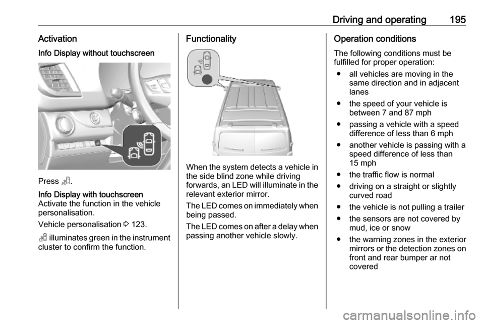
Driving and operating195ActivationInfo Display without touchscreen
Press T.
Info Display with touchscreen
Activate the function in the vehicle
personalisation.
Vehicle personalisation 3 123.
T illuminates green in the instrument
cluster to confirm the function.
Functionality
When the system detects a vehicle in the side blind zone while driving
forwards, an LED will illuminate in the
relevant exterior mirror.
The LED comes on immediately when being passed.
The LED comes on after a delay when
passing another vehicle slowly.
Operation conditions
The following conditions must be
fulfilled for proper operation:
● all vehicles are moving in the same direction and in adjacent
lanes
● the speed of your vehicle is between 7 and 87 mph
● passing a vehicle with a speed difference of less than 6 mph
● another vehicle is passing with a speed difference of less than
15 mph
● the traffic flow is normal
● driving on a straight or slightly curved road
● the vehicle is not pulling a trailer
● the sensors are not covered by mud, ice or snow
● the warning zones in the exterior mirrors or the detection zones on
front and rear bumper ar not
covered
Page 200 of 289
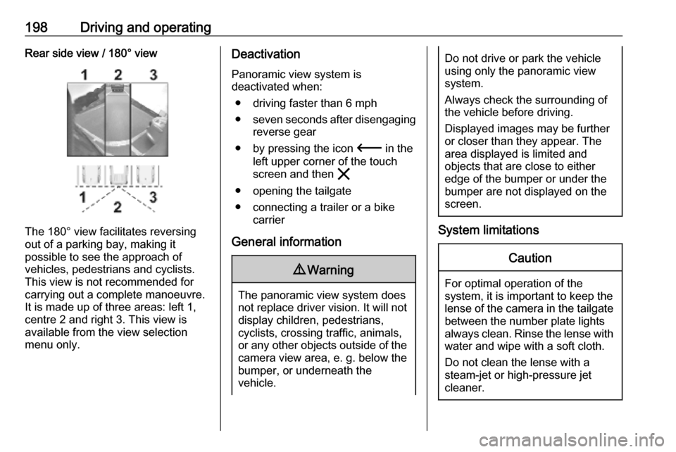
198Driving and operatingRear side view / 180° view
The 180° view facilitates reversing
out of a parking bay, making it
possible to see the approach of
vehicles, pedestrians and cyclists.
This view is not recommended for
carrying out a complete manoeuvre.
It is made up of three areas: left 1,
centre 2 and right 3. This view is
available from the view selection menu only.
Deactivation
Panoramic view system is
deactivated when:
● driving faster than 6 mph
● seven seconds after disengaging
reverse gear
● by pressing the icon 3 in the
left upper corner of the touch
screen and then &
● opening the tailgate
● connecting a trailer or a bike carrier
General information9 Warning
The panoramic view system does
not replace driver vision. It will not display children, pedestrians,
cyclists, crossing traffic, animals,
or any other objects outside of the camera view area, e. g. below the
bumper, or underneath the
vehicle.
Do not drive or park the vehicle
using only the panoramic view
system.
Always check the surrounding of
the vehicle before driving.
Displayed images may be further
or closer than they appear. The
area displayed is limited and
objects that are close to either
edge of the bumper or under the
bumper are not displayed on the
screen.
System limitations
Caution
For optimal operation of the
system, it is important to keep the
lense of the camera in the tailgate between the number plate lightsalways clean. Rinse the lense with water and wipe with a soft cloth.
Do not clean the lense with a
steam-jet or high-pressure jet
cleaner.
Page 201 of 289
Driving and operating199The panoramic view system may not
operate properly when:
● The surrounding is dark.
● The sun or the beam of headlights is shining directly into
the camera lenses.
● During nighttime driving.
● Weather limits visibility, such as fog, rain, or snow.
● The camera lenses are blocked by snow, ice, slush, mud, dirt.
● The vehicle is towing a trailer.
● The vehicle had an accident.
● There are extreme temperature changes.
Rear view camera Depending on version, camera is
mounted above the license plate in
the tailgate / left rear door.9 Warning
The rear view camera does not
replace driver vision. Note that
objects that are outside the
camera's field of view and the
parking assist sensors, e.g. below
the bumper or underneath the
vehicle, are not displayed.
Do not reverse or park the vehicle
using only the rear view camera.
Always check the surrounding of
the vehicle before driving.
The view of the camera is displayed
in the Info Display 3 119 or in the
interior mirror 3 40.
The area displayed by the camera is
limited. The distance of the image that
appears on the display differs from
the actual distance.
Switching on Rear view camera is automatically
activated when reverse gear is
engaged.
Switching off
The camera is switched off when a
forward gear is engaged.
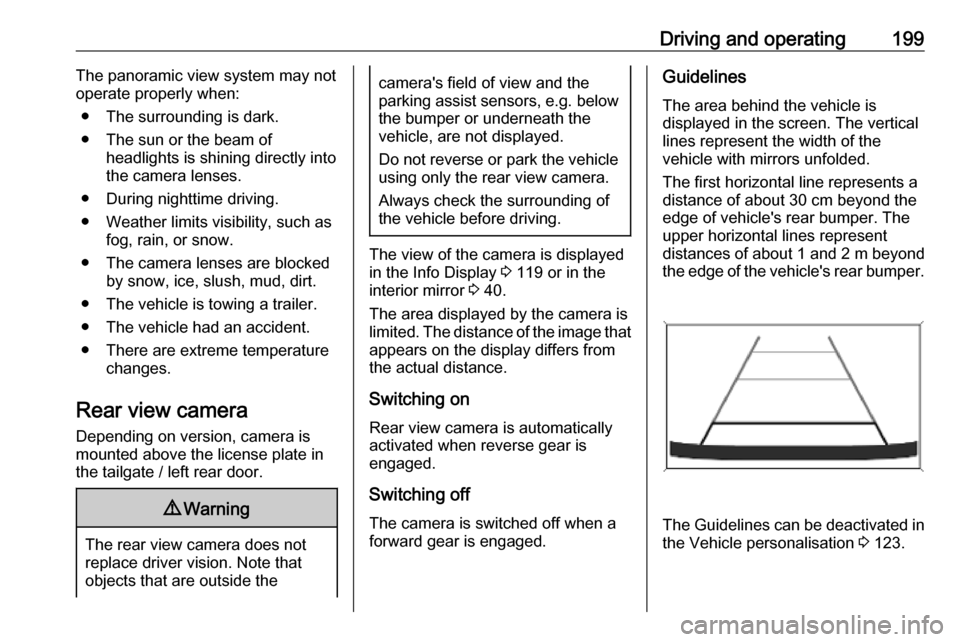
Guidelines
The area behind the vehicle is
displayed in the screen. The vertical
lines represent the width of the
vehicle with mirrors unfolded.
The first horizontal line represents a
distance of about 30 cm beyond the
edge of vehicle's rear bumper. The
upper horizontal lines represent
distances of about 1 and 2 m beyond
the edge of the vehicle's rear bumper.
The Guidelines can be deactivated in
the Vehicle personalisation 3 123.
Page 206 of 289
204Driving and operatingArctic grade diesel fuel can be used
in extreme low temperatures below
-20 °C. Using this fuel grade in warm
or hot climates is not recommended
and may cause engine stalling, poor
starting or damage on the fuel
injection system.
Refuelling9 Danger
Before refuelling, switch off
ignition and any external heaters
with combustion chambers.
Follow the operating and safety
instructions of the filling station
when refuelling.
9 Danger
Fuel is flammable and explosive.
No smoking. No naked flames or
sparks.
If a smell of fuel can be noticed
inside the vehicle, have the cause of this remedied immediately by aworkshop.
A label with symbols at the fuel filler
flap is indicating the allowed fuel
types. In Europe the pump nozzles of the filling stations are marked with
these symbols. Refuel only the
allowed fuel type.Caution
In case of misfuelling, do not
switch on ignition.
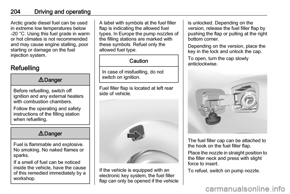
Fuel filler flap is located at left rear
side of vehicle.
If the vehicle is equipped with an
electronic key system, the fuel filler
flap can only be opened if the vehicle
is unlocked. Depending on the
version, release the fuel filler flap by
pushing the flap or pulling at the right bottom corner.
Depending on the version, place the
key in the lock and unlock the cap.
To open, turn the cap slowly
anticlockwise.
The fuel filler cap can be attached to
the hook on the fuel filler flap.
Place the nozzle in straight position to the filler neck and press with slight
force to insert.
To refuel, switch on pump nozzle.
Page 212 of 289

210Vehicle careVehicle careGeneral Information...................211
Accessories and vehicle modifications .......................... 211
Vehicle storage ........................211
End-of-life vehicle recovery .....212
Vehicle checks ........................... 212
Performing work ......................212
Bonnet ..................................... 213
Engine oil ................................. 213
Engine coolant ......................... 214
Washer fluid ............................ 215
Brakes ..................................... 216
Brake fluid ............................... 216
Vehicle battery ......................... 216
Diesel fuel system bleeding .....218
Wiper blade replacement ........219
Bulb replacement .......................219
Halogen headlights ..................219
Xenon headlights .....................223
Front fog lights ......................... 224
Front turn lights .......................224
Tail lights ................................. 225
Side turn lights ......................... 228
Centre high-mounted brake light ......................................... 228Number plate light...................229
Interior lights ............................ 230
Electrical system ........................230
Fuses ....................................... 230
Engine compartment fuse box . 231
Instrument panel fuse box .......231
Vehicle tools .............................. 234
Tools ........................................ 234
Wheels and tyres .......................236
Winter tyres ............................. 236
Tyre designations ....................236
Tyre pressure .......................... 237
Tyre deflation detection
system .................................... 238
Tread depth ............................. 239
Changing tyre and wheel size . 239
Wheel covers ........................... 240
Tyre chains .............................. 240
Tyre repair kit .......................... 240
Wheel changing .......................244
Spare wheel ............................ 245
Jump starting ............................. 249
Towing ....................................... 251
Towing the vehicle ...................251
Towing another vehicle ...........252
Appearance care .......................253
Exterior care ............................ 253Interior care............................. 255
Floor mats ............................... 256
Page 227 of 289
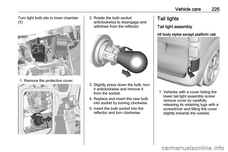
Vehicle care225Turn light bulb sits in inner chamber
( 1 )
1. Remove the protective cover.
2. Rotate the bulb socket
anticlockwise to disengage and
withdraw from the reflector.
3. Slightly press down the bulb, turn it anticlockwise and remove it
from the socket.
4. Replace and insert the new bulb into socket by turning clockwise.
5. Insert the bulb socket into the reflector and turn clockwise.
Tail lights
Tail light assembly All body styles except platform cab
1. Vehicles with a cover hiding the lower tail light assembly screw:
remove cover by carefully
releasing its retaining lugs with a
screwdriver and tilting the cover
slightly towards the outside.
Page 229 of 289
Vehicle care227
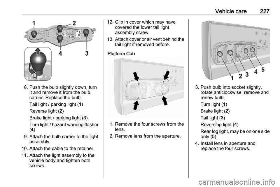
8. Push the bulb slightly down, turnit and remove it from the bulb
carrier. Replace the bulb:
Tail light / parking light ( 1)
Reverse light ( 2)
Brake light / parking light ( 3)
Turn light / hazard warning flasher
( 4 )
9. Attach the bulb carrier to the light assembly.
10. Attach the cable to the retainer.
11. Attach the light assembly to the vehicle body and tighten both
screws.
12. Clip in cover which may have covered the lower tail light
assembly screw.
13. Attach cover or air vent behind the
tail light if removed before.
Platform Cab
1. Remove the four screws from the lens.
2. Remove lens from the aperture.
3. Push bulb into socket slightly, rotate anticlockwise, remove and
renew bulb.
Turn light ( 1)
Brake light ( 2)
Tail light ( 3)
Reversing light ( 4)
Rear fog light, may be on one side
only ( 5)
4. Install lens in aperture and replace the four screws.
Page 230 of 289
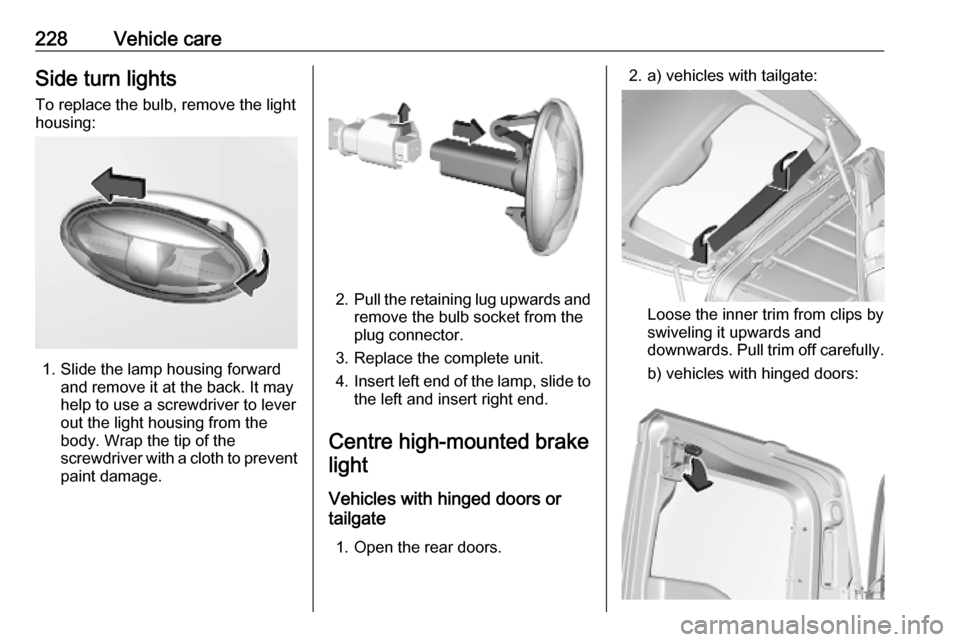
228Vehicle careSide turn lightsTo replace the bulb, remove the light
housing:
1. Slide the lamp housing forward and remove it at the back. It may
help to use a screwdriver to lever
out the light housing from the
body. Wrap the tip of the
screwdriver with a cloth to prevent
paint damage.
2. Pull the retaining lug upwards and
remove the bulb socket from the
plug connector.
3. Replace the complete unit.
4. Insert left end of the lamp, slide to
the left and insert right end.
Centre high-mounted brake light
Vehicles with hinged doors or
tailgate
1. Open the rear doors.
2. a) vehicles with tailgate:
Loose the inner trim from clips by
swiveling it upwards and
downwards. Pull trim off carefully.
b) vehicles with hinged doors:
Page 232 of 289
230Vehicle care2. Pull the bulb from the bulb holderand replace it.
3. Attach the cover.
Interior lights
Have the following lights replaced by
a workshop:
● courtesy light, reading lights
● load compartment light
● instrument panel illuminationElectrical system
Fuses Data on the replacement fuse must
match the data on the defective fuse.
There are two fuse boxes in the
vehicle:
● engine compartment
● instrument panel
Before replacing a fuse, turn off the
respective switch and the ignition.
A blown fuse can be recognised by its melted wire.Caution
Do not replace the fuse until the
cause of the fault has been
remedied.
Some functions are protected by
several fuses.
Fuses may also be inserted without
existence of a function.
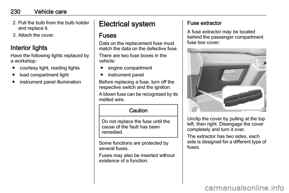
Fuse extractor
A fuse extractor may be located
behind the passenger compartment fuse box cover:
Unclip the cover by pulling at the top
left, then right. Disengage the cover
completely and turn it over.
The extractor has two sides, each side is designed for a different type of
fuses.