Engine VAUXHALL VIVARO C 2020 Manual PDF
[x] Cancel search | Manufacturer: VAUXHALL, Model Year: 2020, Model line: VIVARO C, Model: VAUXHALL VIVARO C 2020Pages: 289, PDF Size: 10.16 MB
Page 233 of 289
Vehicle care231
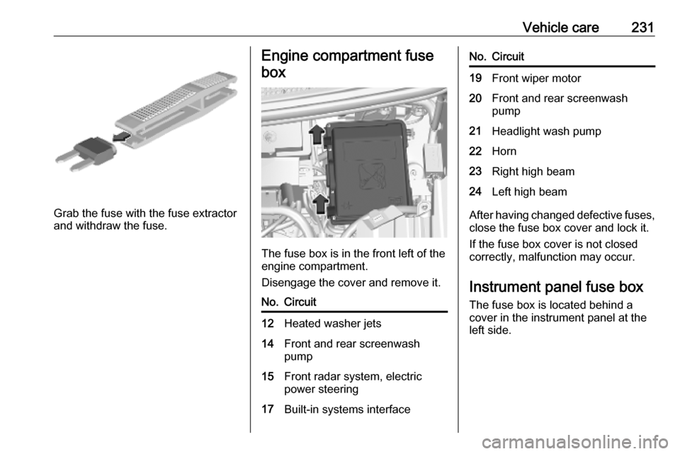
Grab the fuse with the fuse extractor
and withdraw the fuse.
Engine compartment fuse
box
The fuse box is in the front left of the
engine compartment.
Disengage the cover and remove it.
No.Circuit12Heated washer jets14Front and rear screenwash
pump15Front radar system, electric
power steering17Built-in systems interfaceNo.Circuit19Front wiper motor20Front and rear screenwash
pump21Headlight wash pump22Horn23Right high beam24Left high beam
After having changed defective fuses,
close the fuse box cover and lock it.
If the fuse box cover is not closed
correctly, malfunction may occur.
Instrument panel fuse boxThe fuse box is located behind a
cover in the instrument panel at the
left side.
Page 239 of 289
Vehicle care237Directional tyresDirectional tyres should be mounted
so that they rotate in the correct
direction. The proper rotation
direction is indicated by a symbol (e.g. an arrow) on the sidewall.
Tyre pressure
Check the pressure of cold tyres at
least every 14 days and before any
long journey. Do not forget the spare
wheel. This also applies to vehicles
with tyre pressure monitoring system.
Tyre pressure 3 271.
The tyre pressure data refers to cold
tyres. It applies to summer and winter tyres.
Always inflate the spare tyre to the
pressure specified for full load.
Incorrect tyre pressures will impair
safety, vehicle handling, comfort and
fuel economy and will increase tyre
wear.Tyre pressures differ depending on
various options. For the correct tyre
pressure value, follow the procedure
below:
1. Identify the engine identifier code.
Engine data 3 268.
2. Identify the respective tyre.
The tyre pressure tables show all
possible tyre combinations 3 271.
For the tyres approved for your
vehicle, refer to the EEC Certificate of Conformity provided with your vehicle
or other national registration
documents.
The driver is responsible for correct
adjustment of tyre pressure.9 Warning
If the pressure is too low, this can
result in considerable tyre warm-
up and internal damage, leading to tread separation and even to tyre
blow-out at high speeds.
9 Warning
For specific tyres the
recommended tyre pressure as
shown in the tyre pressure table may exceed the maximum tyre
pressure as indicated on the tyre.
Never exceed the maximum tyre
pressure as indicated on the tyre.
Temperature dependency
The tyre pressure depends on the
temperature of the tyre. During
driving, tyre temperature and
pressure increase. Tyre pressure
values provided on the tyre
information label and tyre pressure
chart are valid for cold tyres, which means at 20 °C.
The pressure increases by nearly
1.5 psi for a 10 °C temperature
increase. This must be considered
when warm tyres are checked.
Page 243 of 289
Vehicle care2411.Pull speed limit label from the tyre
repair kit and place it in driver's
visible area.
2. Pull the electrical cable and air hose out of the compartments on
the underside of the kit.
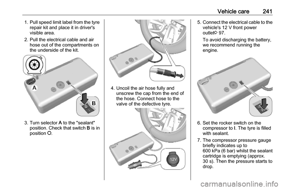
3. Turn selector A to the "sealant"
position. Check that switch B is in
position J.
4. Uncoil the air hose fully and
unscrew the cap from the end of
the hose. Connect hose to the
valve of the defective tyre.
5. Connect the electrical cable to the
vehicle's 12 V front power
outlet 3 97.
To avoid discharging the battery,
we recommend running the
engine.
6. Set the rocker switch on the compressor to I. The tyre is filled
with sealant.
7. The compressor pressure gauge briefly indicates up to
600 kPa (6 bar) whilst the sealant
cartridge is emptying (approx.
30 s). Then the pressure starts to
drop.
Page 252 of 289

250Vehicle care● A discharged vehicle battery canalready freeze at a temperature
of 0 °C. Defrost the frozen battery before connecting jump leads.
● Wear eye protection and protective clothing when
handling a battery.
● Use a booster battery with the same voltage (12 V). Its capacity
(Ah) must not be much less than
that of the discharged vehicle
battery.
● Use jump leads with insulated terminals and a cross section of
at least 16 mm 2
(25 mm 2
for
diesel engines).
● Do not disconnect the discharged
vehicle battery from the vehicle.
● Switch off all unnecessary electrical consumers.
● Do not lean over the vehicle battery during jump starting.
● Do not allow the terminals of one
lead to touch those of the other
lead.● The vehicles must not come into contact with each other during
the jump starting process.
● Apply the parking brake, transmission in neutral,
automatic transmission in P.
Open the positive terminal protection
caps of both vehicle batteries.
Lead connection order: 1. Connect the red lead to the positive terminal of the booster
battery.
2. Connect the other end of the red lead to the positive terminal of the
discharged battery.
3. Connect the black lead to the negative terminal of the boosterbattery.
4. Connect the other end of the black
lead to a vehicle grounding point
of your vehicle in the engine
compartment.
Route the leads so that they cannot
catch on rotating parts in the engine
compartment.
To start the engine: 1. Start the engine of the vehicle providing the jump.
2. After 5 minutes, start the other engine. Start attempts should be
made for no longer than 15
seconds at an interval of 1 minute.
3. Allow both engines to idle for approx. three minutes with the
leads connected.
4. Switch on electrical consumers e.g. headlights, heated rear
window of the vehicle receiving
the jump start.
5. Reverse above sequence exactly when removing leads.
Page 254 of 289
252Vehicle careCaution
Drive slowly. Do not drive jerkily.
Excessive tractive force can
damage the vehicle.
When the engine is not running,
considerably more force is needed to
brake and steer.
To prevent the entry of exhaust gases from the towing vehicle, switch on the
air recirculation and close the
windows.
Vehicles with automatic transmission: The vehicle must be towed facing
forwards, not faster than 50 mph nor further than 60 miles. In all other
cases and when the transmission is
defective, the front axle must be
raised off the ground.
Seek the assistance of a workshop. After towing, unscrew the towing eye.
Insert cap with the flange into the
recess and fix cap by pushing.
Towing another vehicle
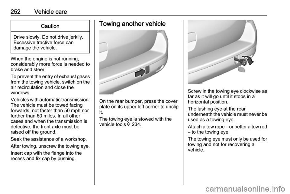
On the rear bumper, press the cover
plate on its upper left corner to unclip it.
The towing eye is stowed with the
vehicle tools 3 234.
Screw in the towing eye clockwise as
far as it will go until it stops in a
horizontal position.
The lashing eye at the rear
underneath the vehicle must never be used as a towing eye.
Attach a tow rope – or better a tow rod
– to the towing eye.
The towing eye must only be used for towing and not for recovering a
vehicle.
Page 256 of 289

254Vehicle careDo not clean the engine compartmentwith a steam-jet or high-pressure jet
cleaner.
Thoroughly rinse and leather-off the
vehicle. Rinse leather frequently. Use
separate leathers for painted and
glass surfaces: remnants of wax on
the windows will impair vision.
Have the door hinges of all doors
greased by a workshop.
Exterior lights
Headlight and other light covers are
made of plastic. Do not use any
abrasive or caustic agents, do not use
an ice scraper, and do not clean them dry.
Polishing and waxing Wax the vehicle regularly at the latest
when water no longer beads.
Otherwise, the paintwork will dry out.
Polishing is necessary only if the paint
has become dull or if solid deposits
have become attached to it.
Paintwork polish with silicone forms a
protective film, making waxing
unnecessary.Plastic body parts must not be treated with wax or polishing agents.
Windows and wiper blades Switch off wipers before handling in
their areas.
Use a soft lint-free cloth or chamois
leather together with window cleaner
and insect remover.
Use only water-repellent products
approved for the vehicle.
When cleaning the rear window from
inside, always wipe in parallel to the
heating element to prevent damage.
For mechanical removal of ice, use a
sharp-edged ice scraper. Press the
scraper firmly against the glass so
that no dirt can get under it and
scratch the glass.
Clean smearing wiper blades with a
soft cloth and window cleaner.
Remove dirt residues from smearing
wiper blades by using a soft cloth and
window cleaner. Also make sure to
remove any residues such as wax,
insect residues and similar from the
window.Ice residues, pollution and continuous
wiping on dry windows will damage or
even destroy the wiper blades.
Glass panel Never clean with solvents or abrasive
agents, fuels, aggressive media e.g.
paint cleaner, acetone-containing
solutions, acidic or highly alkaline
media or abrasive pads.
Wheels and tyres
Do not use high-pressure jet
cleaners.
Clean rims with a pH-neutral wheel
cleaner.
Rims are painted and can be treated
with the same agents as the body.
Paintwork damageRectify minor paintwork damage witha touch-up pen before rust forms.
Have more extensive damage or rust
areas repaired by a workshop.
Page 262 of 289

260Service and maintenanceService intervals
Engine code
DV5RC
DV5RD
DW10FDU
DW10FCU
DW10FEU
DV6DU
DW10F
Country group 125,000 miles / 2 year 1)32,000 miles / 2 yearCountry group 225,000 miles / 2 year32,000 miles / 2 yearCountry group 312,500 miles / 1 year12,500 miles / 1 yearCountry group 412,500 miles / 1 year12,500 miles / 1 year12,500 miles / 1 yearCountry group 56,000 miles / 1 year12,500 miles / 1 year6,000 miles / 1 year1)
Unless otherwise indicated in the service display.Country Group 1:
Andorra, Austria, Belgium,Cyprus, Denmark, Finland, France, Germany, Greece, Iceland, Ireland, Italy, Liechtenstein, Luxembourg, Malta, Monaco, Netherlands, Norway, Portugal, San Marino, Spain, Sweden, Switzerland, United Kingdom.Country Group 2:
Bosnia-Herzegovina, Bulgaria, Croatia, Czech Republic, Estonia, Hungary, Latvia, Lithuania, Macedonia, Poland,
Romania, Slovakia, Slovenia.Country Group 3:
Albania, Montenegro, Serbia.Country Group 4:
Israel, South Africa, Turkey.Country Group 5:
All other countries which are not listed in the previous country groups. (International interval)
Page 264 of 289
262Service and maintenanceRecommended fluids,lubricants and parts
Recommended fluids and lubricants
Only use products that meet the
recommended specifications.9 Warning
Operating materials are
hazardous and could be
poisonous. Handle with care. Pay
attention to information given on
the containers.
Engine oil
Engine oil is identified by its quality
and its viscosity. Quality is more
important than viscosity when
selecting which engine oil to use. The oil quality ensures e.g. engine
cleanliness, wear protection and oil
aging control, whereas viscosity
grade gives information on the oil's
thickness over a temperature range.
Select the appropriate engine oil
based on its quality and on the
minimum ambient temperature
3 266.
Topping up engine oilCaution
In case of any spilled oil, wipe it up and dispose it properly.
Engine oils of different manufacturersand brands can be mixed as long as
they comply with the required engine
oil quality and viscosity.
Use of engine oils for all petrol
engines with only ACEA quality is
prohibited, since it can cause engine
damage under certain operating
conditions.
Select the appropriate engine oil
based on its quality and on the
minimum ambient temperature
3 266.
Additional engine oil additives
The use of additional engine oil
additives could cause damage and
invalidate the warranty.
Engine oil viscosity grades
The SAE viscosity grade gives
information of the thickness of the oil.
Multigrade oil is indicated by two
figures, e.g. SAE 5W-30. The first
figure, followed by a W, indicates the
low temperature viscosity and the
second figure the high temperature viscosity.
Select the appropriate viscosity grade depending on the minimum ambient
temperature 3 266.
All of the recommended viscosity
grades are suitable for high ambient
temperatures.
Coolant and antifreeze
Use only organic acid type-long life
coolant (LLC) antifreeze approved for
the vehicle. Consult a workshop.
The system is factory filled with
coolant designed for excellent
corrosion protection and frost
protection down to approx. -37 °C.
This concentration should be
maintained all year round. The use of additional coolant additives that
intend to give additional corrosion
Page 266 of 289

264Technical dataTechnical dataVehicle identification..................264
Vehicle Identification Number ..264
Identification plate ...................264
Engine identification ................265
Vehicle data ............................... 266
Recommended fluids and lubricants ................................ 266
Engine data ............................. 268
Vehicle dimensions .................270
Capacities ................................ 270
Tyre pressures ........................ 271Vehicle identification
Vehicle IdentificationNumber
The Vehicle Identification Number
may be embossed on the instrument
panel, visible through the windscreen.
Identification plate
The identification plate is located on
the front left or right door frame.
Page 267 of 289

Technical data265Information on identification label:1:manufacturer2:type approval number3:vehicle identification number4:permissible gross vehicle weightrating in kg5:permissible gross train weight
in kg6:maximum permissible front axle
load in kg7:maximum permissible rear axle
load in kg8:vehicle-specific or country-
specific data
The combined total of front and rear
axle loads must not exceed the
permissible gross vehicle weight.
Vehicle's kerb weight depends on the
specification of the vehicle, e.g.
optional equipment and accessories. Refer to the EEC Certificate of
Conformity provided with your vehicle
or other national registration
documents.
The technical data is determined in
accordance with European
Community standards. We reserve
the right to make modifications.
Specifications in the vehicle
documents always have priority over
those given in this manual.
Engine identification
The technical data tables show the
engine identifier code.
Engine data 3 268.
To identify the respective engine,
refer to the engine power in the EEC
Certificate of Conformity provided
with your vehicle or other national
registration documents.