ECU VAUXHALL ZAFIRA TOURER 2014 Owner's Manual
[x] Cancel search | Manufacturer: VAUXHALL, Model Year: 2014, Model line: ZAFIRA TOURER, Model: VAUXHALL ZAFIRA TOURER 2014Pages: 297, PDF Size: 8.87 MB
Page 21 of 297

Keys, doors and windows19Keys, doors and
windowsKeys, locks ................................... 19
Doors ........................................... 24
Vehicle security ............................ 25
Exterior mirrors ............................ 28
Interior mirrors ............................. 29
Windows ...................................... 30
Roof ............................................. 33Keys, locks
Keys Replacement keys
The key number is specified in the
Car Pass or on a detachable tag.
The key number must be quoted
when ordering replacement keys as it
is a component of the immobiliser
system.
Locks 3 262.
Lock cylinders
Designed to free-wheel if they are
forcefully rotated without the correct
key or if the correct key is not fully
inserted. To reset, turn cylinder with
the correct key until its slot is vertical, remove key and then re-insert it. If the
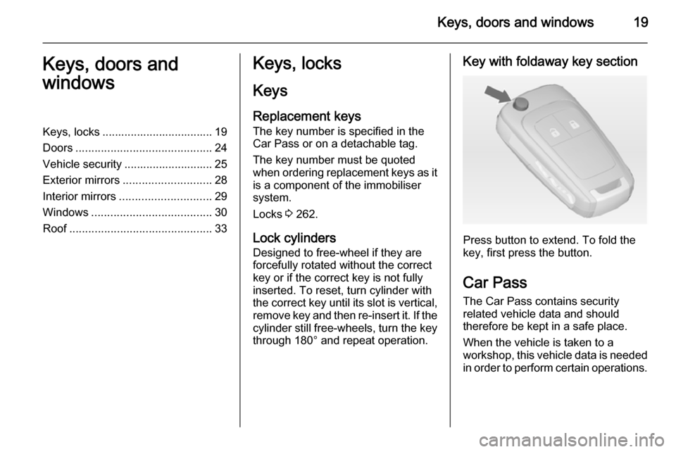
cylinder still free-wheels, turn the key through 180° and repeat operation.Key with foldaway key section
Press button to extend. To fold the
key, first press the button.
Car Pass The Car Pass contains security
related vehicle data and should
therefore be kept in a safe place.
When the vehicle is taken to a
workshop, this vehicle data is needed
in order to perform certain operations.
Page 25 of 297

Keys, doors and windows23
Fault in radio remote control
system
Unlocking
Manually unlock the driver's door by
turning the key in the lock. Switch on
the ignition and press the central
locking button c to unlock all doors,
load compartment and fuel filler flap.
By switching on the ignition, the anti-
theft locking system is deactivated.
Locking
Manually lock the driver's door by
turning the key in the lock.
Fault in central locking system
Unlocking
Manually unlock the driver's door by
turning the key in the lock. The other
doors can be opened by pulling the
interior handle twice. The load
compartment and fuel filler flap
cannot be opened. To deactivate the
anti-theft locking system, switch on
the ignition 3 25.
Locking
Push inside locking knob of all doors
except driver's door. Then close the
driver's door and lock it from the
outside with the key. The fuel filler flap and tailgate cannot be locked.
Automatic locking
This security feature can be
configured to automatically lock all
doors, load compartment and fuel
filler flap as soon as a certain speed
is exceeded.
Additionally it is configurable to
unlock the driver's door or all doors
after the ignition is switched off andthe ignition key is removed (manual
transmission) or the selector lever is
moved to P position (automatic
transmission).
Settings can be changed in the menu Settings in the Info-Display. Vehicle
personalisation 3 128.
The settings can be saved for the key being used 3 21.
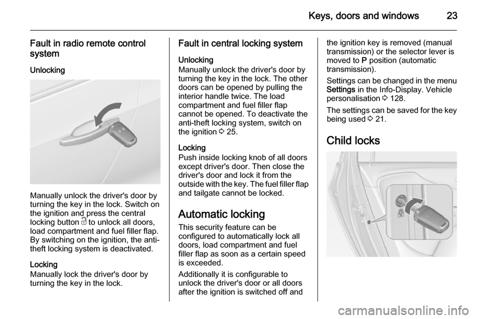
Child locks
Page 27 of 297

Keys, doors and windows25
General hints for operating
tailgate9 Danger
Do not drive with the tailgate open
or ajar, e.g. when transporting
bulky objects, since toxic exhaust
gases, which cannot be seen or
smelled, could enter the vehicle.
This can cause unconsciousness
and even death.
Caution
Before opening the tailgate, check overhead obstructions, e.g. a
garage door, to avoid damage to
the tailgate. Always check the
moving area above and behind the
tailgate.
Notice
The installation of certain heavy
accessories onto the tailgate may
affect its ability to remain open.
Vehicle security
Anti-theft locking system9 Warning
Do not use the system if there are
people in the vehicle! The doorscannot be unlocked from the
inside.
The system deadlocks all the doors.
All doors must be closed otherwise
the system cannot be activated.
If the ignition was on, the driver's door
must be opened and closed once so
that the vehicle can be secured.
Unlocking the vehicle disables the
mechanical anti-theft locking system.
This is not possible with the central
locking button.
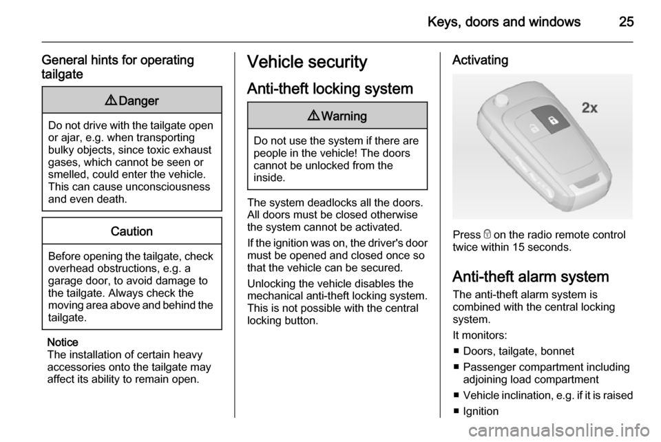
Activating
Press e on the radio remote control
twice within 15 seconds.
Anti-theft alarm system The anti-theft alarm system is
combined with the central locking
system.
It monitors: ■ Doors, tailgate, bonnet
■ Passenger compartment including adjoining load compartment
■ Vehicle inclination, e.g. if it is raised
■ Ignition
Page 56 of 297

54Seats, restraints
Additionally there is a warning label
on the side of the instrument panel,
visible when the front passenger door
is open, or on the front passenger sun
visor.
The front airbag system is triggered in the event of a front-end impact of a
certain severity. The ignition must be
switched on.The inflated airbags cushion the
impact, thereby reducing the risk of
injury to the upper body and head of
the front seat occupants
considerably.
9 Warning
Optimum protection is only
provided when the seat is in the
proper position.
Seat position 3 37.
Keep the area in which the airbag
inflates clear of obstructions.
Fit the seat belt correctly and
engage securely. Only then is the
airbag able to protect.
Side airbag system
The side airbag system consists of an
airbag in each front seat backrest.
This can be identified by the word
AIRBAG .
The side airbag system is triggered in the event of a side impact of a certain
severity. The ignition must be
switched on.
Page 60 of 297

58Seats, restraints
Allow children to enter and exit the
vehicle only on the side facing away
from the traffic.
When the child restraint system is not in use, secure the seat with a seat beltor remove it from the vehicle.
Notice
Do not affix anything on the child restraint systems and do not cover
them with any other materials.
A child restraint system which has
been subjected to stress in an
accident must be replaced.
Page 61 of 297

Seats, restraints59Child restraint installation locationsPermissible options for fitting a child restraint system
Weight and age class
On front passenger seatOn outboard seats in the second rowOn centre seat in
the second rowOn seats in the third rowactivated airbagdeactivated airbagGroup 0: up to 10 kg
or approx. 10 monthsXU 1U2XUGroup 0+: up to 13 kg
or approx. 2 yearsXU 1U2XUGroup I: 9 to 18 kg
or approx. 8 months to 4 yearsXU 1U2XUGroup II: 15 to 25 kg
or approx. 3 to 7 yearsXXUXUGroup III: 22 to 36 kg
or approx. 6 to 12 yearsXXUXU1=Only if front passenger seat airbag system is deactivated. If the child restraint system is being secured using a three- point seat belt, move seat height adjustment to uppermost position and ensure that vehicle safety belt runs forwards
from the upper anchorage point. Adjust seat backrest inclination as far as necessary to a vertical position to ensure
that the belt is tight on the buckle side.2=Seat available with ISOFIX and Top-Tether mounting brackets 3 62.U=Universal suitability in conjunction with three-point seat belt.X=No child restraint system permitted in this weight class.
Page 66 of 297

64StorageCupholders
Front cupholder
Cupholders are located in the centre
console between the front seats.
Slidable cupholder in
FlexConsole armrest
The cupholder can be moved in guide rails in the FlexConsole armrest or
completely removed.
Push the handle in front of cupholder
to slide.
Armrest 3 42.
Remove cupholder
Pull the handle in front of cupholder
and remove it vertically out of the
console.
Installation in reverse order.
Notice
Install the cupholder in the direction as shown in the illustration.
Otherwise the cupholder may not engage properly.
Page 70 of 297

68StorageRear carrier systemRear carrier system for four
bicycles
The rear carrier system (Flex-Fix
system) allows two bicycles to be
attached to a pull-out carrier
integrated into the vehicle floor. It is
possible to attach two further bicycles
on an adapter. The transportation of
other objects is not permitted.
The maximum load of the rear carrier
system is 80 kg with attached adapter and 60 kg without attached adapter.The maximum load per bicycle on the
pull-out carrier is 30 kg. This allows
the attachment of electrically-
powered bicycles to the pull-out
carrier. The maximum load per
bicycle on the adapter is 20 kg.
The wheelbase of a bicycle must not
exceed 1.15 metres. Otherwise the
secure fastening of a bicycle is not
possible.
If not in use, the rear carrier system
must be slid back into the vehicle
floor.
There must not be any objects on the bicycles that could become loose
during transportation.Caution
If the rear carrier system is
extended and the vehicle is fully loaded, the chassis clearance will
be reduced.
Drive carefully whenever the road has a steep inclination or when
driving over a ramp, bump, etc.
Caution
Consult your bicycle dealer before
attaching bicycles with carbon
frames. The bicycles might get
damaged.
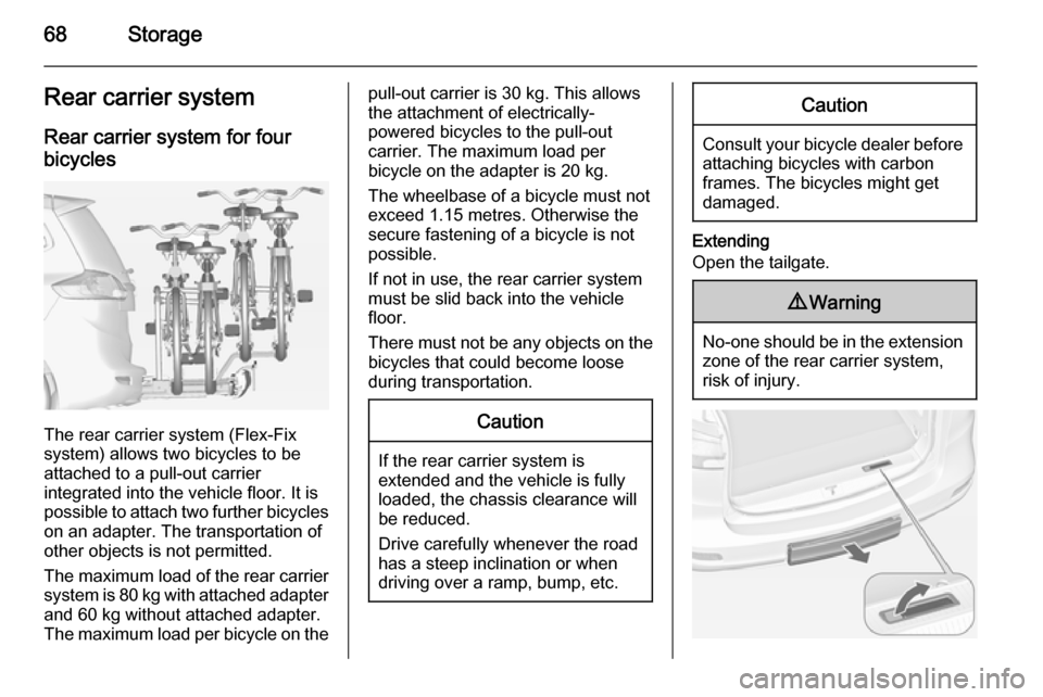
Extending
Open the tailgate.
9 Warning
No-one should be in the extension
zone of the rear carrier system,
risk of injury.
Page 73 of 297

Storage71
1. Rotate the pedals into position asshown in the illustration and put
the bicycle on the foremost wheel
recess.
Make sure that the bicycle stands centrally on the wheel recesses.
2. Attach the short mounting bracket
to the bicycle frame. Turn the
knob clockwise to fasten.
3. Secure both bicycle wheels to the
wheel recesses using the strap
retainers.
4. Check the bicycle to make sure it is secure.
Caution
Ensure gap between bicycle and
vehicle is at least 5 cm. If
necessary, loosen handlebar and swivel sideways.
Attaching the adapter
When carrying more than two
bicycles, the adapter must be fixed
before the second bicycle is attached.
1. Attach the adapter to the rear
carrier system as shown in the
illustration.
Page 74 of 297

72Storage
2. Turn the lever (1) forwards andhold, then lower the adapter (2) at
the rear.
3. Release lever and check if the adapter is engaged securely.4. Guide the strap attached to the adapter underneath the lever to
fold back the rear carrier system.
Fasten the strap.
Attaching further bicycles
The attachment of further bicycles is
similar to the attachment of the first
bicycle. Additionally some steps must be considered:
1. Before putting on the bicycle, always unfold the wheel recesses
for the next bicycle, if necessary.
2. Always rotate the pedals into an appropriate position before
putting on the bicycle.3. Position the bicycles on the rear carrier system alternately aligned
to the left and to the right.
4. Align the bicycles to the one attached before. The wheel hubsof the bicycles must not touch
each other.
5. Attach the bicycles with mounting brackets and strap retainers as
described for the first bicycle. The mounting brackets should be
fixed in parallel.
Use the long mounting bracket to
attach the second bicycle to the
rack.