Automat VAUXHALL ZAFIRA TOURER 2016 Manual Online
[x] Cancel search | Manufacturer: VAUXHALL, Model Year: 2016, Model line: ZAFIRA TOURER, Model: VAUXHALL ZAFIRA TOURER 2016Pages: 305, PDF Size: 9.15 MB
Page 198 of 305
196Driving and operating
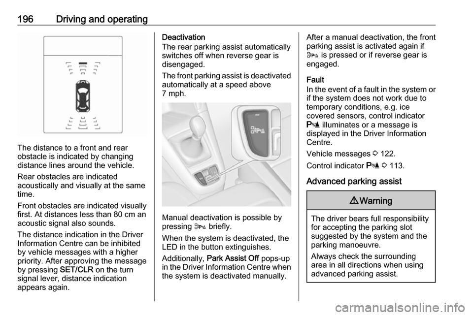
The distance to a front and rear
obstacle is indicated by changing
distance lines around the vehicle.
Rear obstacles are indicated
acoustically and visually at the same
time.
Front obstacles are indicated visually
first. At distances less than 80 cm an
acoustic signal also sounds.
The distance indication in the Driver
Information Centre can be inhibited
by vehicle messages with a higher
priority. After approving the message
by pressing SET/CLR on the turn
signal lever, distance indication
appears again.
Deactivation
The rear parking assist automatically
switches off when reverse gear is
disengaged.
The front parking assist is deactivated
automatically at a speed above
7 mph.
Manual deactivation is possible by
pressing D briefly.
When the system is deactivated, the
LED in the button extinguishes.
Additionally, Park Assist Off pops-up
in the Driver Information Centre when the system is deactivated manually.
After a manual deactivation, the front
parking assist is activated again if
D is pressed or if reverse gear is
engaged.
Fault
In the event of a fault in the system or if the system does not work due to
temporary conditions, e.g. ice
covered sensors, control indicator
r illuminates or a message is
displayed in the Driver Information
Centre.
Vehicle messages 3 122.
Control indicator r 3 113.
Advanced parking assist9 Warning
The driver bears full responsibility
for accepting the parking slot
suggested by the system and the
parking manoeuvre.
Always check the surrounding
area in all directions when using
advanced parking assist.
Page 202 of 305

200Driving and operatingBasic notes on parking assist
systems9 Warning
Under certain circumstances,
various reflective surfaces on
objects or clothing as well as
external noise sources may cause the system to fail to detect
obstacles.
Special attention must be paid to
low obstacles which can damage
the lower part of the bumper.
Caution
Performance of the system can be reduced when sensors are
covered, e.g. by ice or snow.
Performance of the parking assist
system can be reduced due to
heavy loading.
Special conditions apply if there
are taller vehicles in the vicinity
(e.g. off-road vehicles, mini vans,
vans). Object identification and
correct distance indication in the
upper part of these vehicles
cannot be guaranteed.
Objects with a very small reflection
cross-section, e.g. objects of
narrow size or soft materials, may
not be detected by the system.
Parking assist systems do not
detect objects outside the
detection range.
Notice
The parking assist system can be
activated and deactivated by
changing the settings in the
Info-Display. If a trailer coupling is
attached, it must be selected in the
menu.
Vehicle personalisation 3 129.
Notice
The parking assist system
automatically detects factory-fitted
towing equipment. It is deactivated
when the connector is plugged in.
It is possible that the sensor detects
a non-existing object (echo
disturbance) caused by external acoustical or mechanic
disturbances.
Advanced parking assist system
may not respond to changes in the
parking space after initiating a
parallel parking manoeuvre.
Notice
If engaging a forward gear and
exceeding a certain speed, the rear
parking assist will be deactivated
when the rear carrier system is
extended.
If engaging reverse gear first, the
parking assist will detect the rear
carrier system and provide a buzzing sound. Press D briefly to
deactivate the parking assist.
Notice
After production, the advanced
parking assist requires a calibration.
For optimal parking guidance, a
driving distance of at least 22 miles,
including a number of bends, is
required.
Page 204 of 305
202Driving and operatingby approx. 3 metres. The height of thezone is approx. between 0.5 metres
and 2 metres off the ground.
The system is deactivated if the
vehicle is towing a trailer.
Side blind spot alert is designed to ignore stationary objects such as
guardrails, posts, curbs, walls and
beams. Parked vehicles or oncoming
vehicles are not detected.
Fault
Occasional missed alerts can occur under normal circumstances and will
increase in wet conditions.
Side blind spot alert does not operate when the left or right corners of the
rear bumper are covered with mud,
dirt, snow, ice, slush, or in heavy
rainstorms. Cleaning instructions
3 264.
In the event of a fault in the system or if the system does not work due to
temporary conditions, a message is
displayed in the Driver Information
Centre. Seek the assistance of a
workshop in case of a permanent fault.Rear view camera
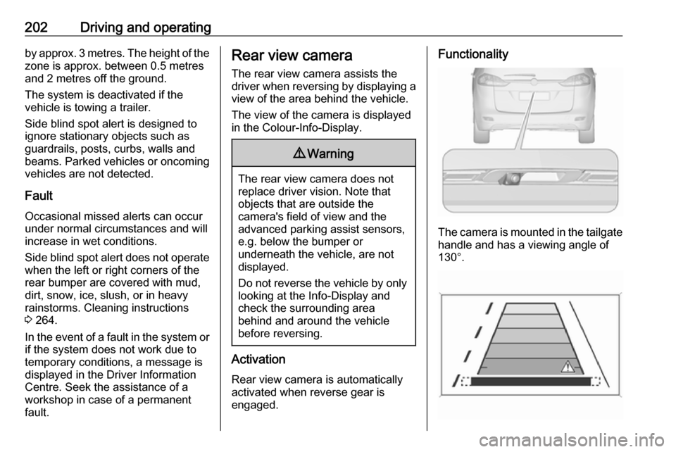
The rear view camera assists the
driver when reversing by displaying a view of the area behind the vehicle.
The view of the camera is displayed
in the Colour-Info-Display.9 Warning
The rear view camera does not
replace driver vision. Note that
objects that are outside the
camera's field of view and the
advanced parking assist sensors,
e.g. below the bumper or
underneath the vehicle, are not
displayed.
Do not reverse the vehicle by only looking at the Info-Display and
check the surrounding area
behind and around the vehicle
before reversing.
Activation
Rear view camera is automatically
activated when reverse gear is
engaged.
Functionality
The camera is mounted in the tailgate handle and has a viewing angle of
130°.
Page 211 of 305
Driving and operating209Fuel for natural gasoperation
Use natural gas with a methane
content of approx. 78 - 99%. L-gas
(low) has approx. 78 - 87% and H-gas (high) has approx. 87 - 99%. Biogas
with the same methane content can
also be used if it has been chemically
prepared and desulphurised.
Only use natural gas or biogas that
complies with DIN 51624.
Liquid gas or LPG must not be used.
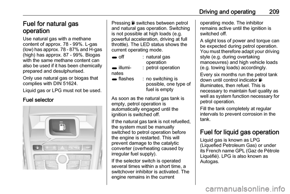
Fuel selectorPressing Y switches between petrol
and natural gas operation. Switching
is not possible at high loads (e.g.
powerful acceleration, driving at full
throttle). The LED status shows the
current operating mode.1 off:natural gas
operation1 illumi‐
nates:petrol operation1 flashes:no switching is
possible, one type of
fuel is empty
As soon as the natural gas tank is empty, petrol operation is
automatically engaged until the
ignition is switched off.
If the natural gas tank is not refuelled, the system must be manually
switched to petrol operation before
the engine is restarted. This will
prevent damage to the catalytic
converter (overheating caused by
irregular fuel supply).
If the selector switch is operated
several times within a short time, a
switchover inhibitor is activated. The
engine remains in the current
operating mode. The inhibitor
remains active until the ignition is
switched off.
A slight loss of power and torque can
be expected during petrol operation.
You must therefore adapt your driving style (e.g. during overtaking
manoeuvres) and high vehicle loads
(e.g. towing loads) accordingly.
Every six months run the petrol tank
down until control indicator Y
illuminates, then refuel. This is
necessary to maintain fuel quality as
well as system function necessary for
petrol operation.
Fill the tank completely at regular
intervals to prevent corrosion in the
tank.
Fuel for liquid gas operation
Liquid gas is known as LPG
(Liquefied Petroleum Gas) or under
its French name GPL (Gaz de Pétrole Liquéfié). LPG is also known as
Autogas.
Page 212 of 305
210Driving and operatingLPG consists mainly of propane and
butane. The octane rating is between 105 and 115, depending on the
butane proportion. LPG is stored
liquid at around 5 - 10 bar pressure.
The boiling point depends on the
pressure and mixing ratio. At ambient
pressure, it is between -42 °C (pure
propane) and -0.5 °C (pure butane).Caution
The system works at an ambient
temperature of approx. -8 °C to
100 °C.
Full function of the LPG system can only be guaranteed with liquid gas
which complies with the minimum
requirements of DIN EN 589.
Fuel selector
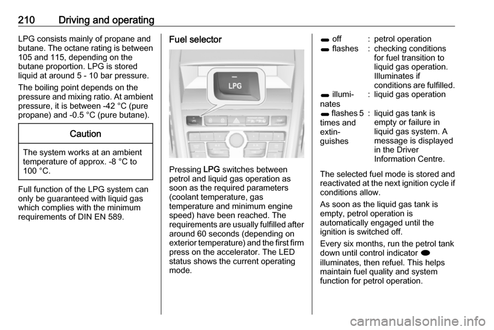
Pressing LPG switches between
petrol and liquid gas operation as
soon as the required parameters (coolant temperature, gas
temperature and minimum engine
speed) have been reached. The
requirements are usually fulfilled after
around 60 seconds (depending on
exterior temperature) and the first firm press on the accelerator. The LED
status shows the current operating
mode.
1 off:petrol operation1 flashes:checking conditions
for fuel transition to
liquid gas operation.
Illuminates if
conditions are fulfilled.1 illumi‐
nates:liquid gas operation1 flashes 5
times and
extin‐
guishes:liquid gas tank is
empty or failure in
liquid gas system. A
message is displayed
in the Driver
Information Centre.
The selected fuel mode is stored and
reactivated at the next ignition cycle if
conditions allow.
As soon as the liquid gas tank is
empty, petrol operation is
automatically engaged until the
ignition is switched off.
Every six months, run the petrol tank down until control indicator i
illuminates, then refuel. This helps
maintain fuel quality and system
function for petrol operation.
Page 214 of 305
212Driving and operating9Danger
Fuel is flammable and explosive.
No smoking. No naked flames or
sparks.
If you can smell fuel in your
vehicle, have the cause of this
remedied immediately by a
workshop.
Caution
In case of misfuelling, do not
switch on ignition.
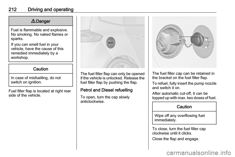
Fuel filler flap is located at right rear
side of the vehicle.
The fuel filler flap can only be opened
if the vehicle is unlocked. Release the
fuel filler flap by pushing the flap.
Petrol and Diesel refuelling To open, turn the cap slowly
anticlockwise.The fuel filler cap can be retained in
the bracket on the fuel filler flap.
To refuel, fully insert the pump nozzle
and switch it on.
After automatic cut-off, it can be
topped up with max. two doses of fuel.
Caution
Wipe off any overflowing fuel
immediately.
To close, turn the fuel filler cap
clockwise until it clicks.
Close the flap and engage.
Page 217 of 305
Driving and operating215
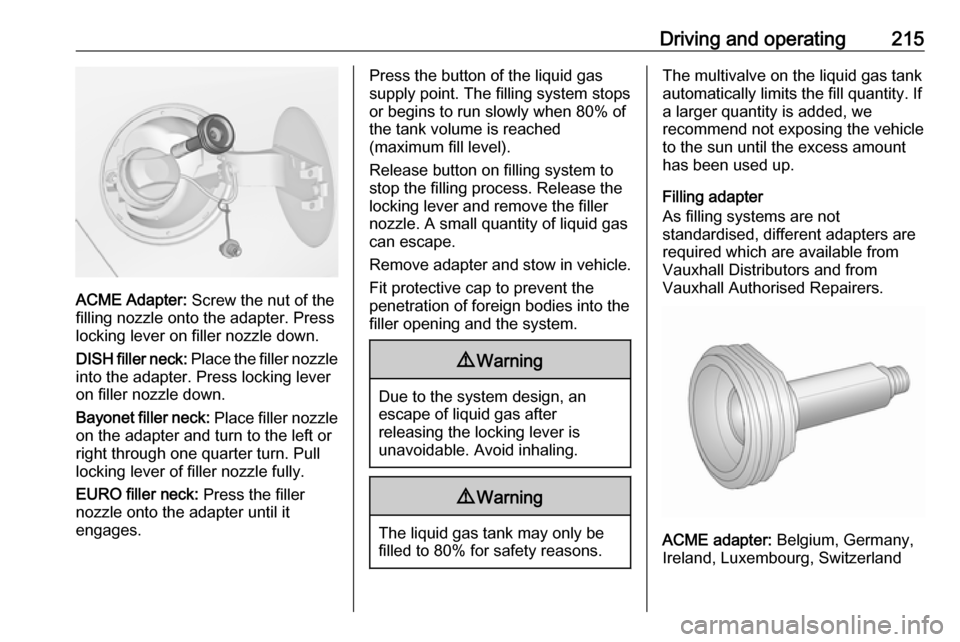
ACME Adapter: Screw the nut of the
filling nozzle onto the adapter. Press
locking lever on filler nozzle down.
DISH filler neck: Place the filler nozzle
into the adapter. Press locking lever
on filler nozzle down.
Bayonet filler neck: Place filler nozzle
on the adapter and turn to the left or
right through one quarter turn. Pull
locking lever of filler nozzle fully.
EURO filler neck: Press the filler
nozzle onto the adapter until it
engages.
Press the button of the liquid gas supply point. The filling system stops
or begins to run slowly when 80% of
the tank volume is reached
(maximum fill level).
Release button on filling system to
stop the filling process. Release the
locking lever and remove the filler
nozzle. A small quantity of liquid gas
can escape.
Remove adapter and stow in vehicle. Fit protective cap to prevent the
penetration of foreign bodies into the
filler opening and the system.9 Warning
Due to the system design, an
escape of liquid gas after
releasing the locking lever is
unavoidable. Avoid inhaling.
9 Warning
The liquid gas tank may only be
filled to 80% for safety reasons.
The multivalve on the liquid gas tank
automatically limits the fill quantity. If
a larger quantity is added, we
recommend not exposing the vehicle
to the sun until the excess amount
has been used up.
Filling adapter
As filling systems are not
standardised, different adapters are
required which are available from
Vauxhall Distributors and from
Vauxhall Authorised Repairers.
ACME adapter: Belgium, Germany,
Ireland, Luxembourg, Switzerland
Page 227 of 305
Vehicle care225
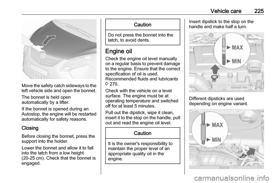
Move the safety catch sideways to theleft vehicle side and open the bonnet.
The bonnet is held open
automatically by a lifter.
If the bonnet is opened during an
Autostop, the engine will be restarted automatically for safety reasons.
Closing Before closing the bonnet, press the
support into the holder.
Lower the bonnet and allow it to fall
into the latch from a low height
(20-25 cm). Check that the bonnet is
engaged.
Caution
Do not press the bonnet into the
latch, to avoid dents.
Engine oil
Check the engine oil level manually
on a regular basis to prevent damage
to the engine. Ensure that the correct specification of oil is used.
Recommended fluids and lubricants
3 270.
Check with the vehicle on a level
surface. The engine must be at
operating temperature and switched
off for at least 5 minutes.
Pull out the dipstick, wipe it clean, insert it to the stop on the handle, pull
out and read the engine oil level.
Caution
It is the owner's responsibility to
maintain the proper level of an
appropriate quality oil in the
engine.
Insert dipstick to the stop on the
handle and make half a turn.
Different dipsticks are used
depending on engine variant.
Page 251 of 305
Vehicle care249Each time the tyres are replaced, tyre
pressure monitoring system sensors
must be dismounted and serviced. For the screwed sensor, replace
valve core and sealing ring. For
clipped sensor, replace complete
valve stem.
Vehicle loading status
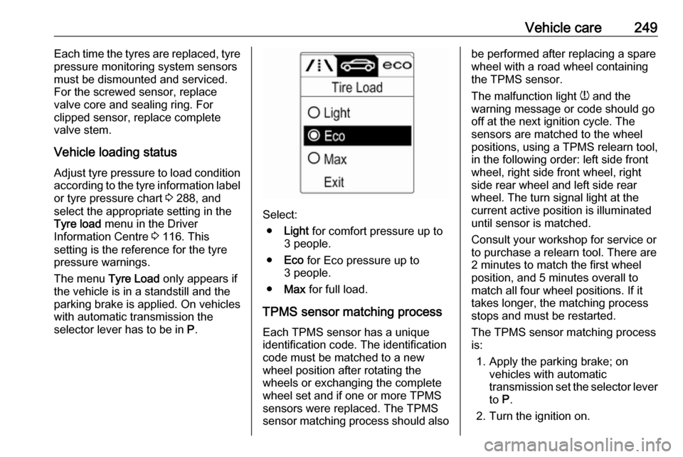
Adjust tyre pressure to load condition according to the tyre information labelor tyre pressure chart 3 288, and
select the appropriate setting in the
Tyre load menu in the Driver
Information Centre 3 116. This
setting is the reference for the tyre
pressure warnings.
The menu Tyre Load only appears if
the vehicle is in a standstill and the
parking brake is applied. On vehicles
with automatic transmission the
selector lever has to be in P.
Select:
● Light for comfort pressure up to
3 people.
● Eco for Eco pressure up to
3 people.
● Max for full load.
TPMS sensor matching process Each TPMS sensor has a unique
identification code. The identification
code must be matched to a new
wheel position after rotating the
wheels or exchanging the complete
wheel set and if one or more TPMS
sensors were replaced. The TPMS sensor matching process should also
be performed after replacing a spare
wheel with a road wheel containing
the TPMS sensor.
The malfunction light w and the
warning message or code should go
off at the next ignition cycle. The
sensors are matched to the wheel
positions, using a TPMS relearn tool,
in the following order: left side front
wheel, right side front wheel, right
side rear wheel and left side rear
wheel. The turn signal light at the
current active position is illuminated
until sensor is matched.
Consult your workshop for service or
to purchase a relearn tool. There are
2 minutes to match the first wheel
position, and 5 minutes overall to
match all four wheel positions. If it
takes longer, the matching process
stops and must be restarted.
The TPMS sensor matching process
is:
1. Apply the parking brake; on vehicles with automatic
transmission set the selector lever
to P.
2. Turn the ignition on.
Page 263 of 305
Vehicle care261●A discharged battery can already
freeze at a temperature of 0 °C.
Defrost the frozen battery before
connecting jump leads.
● Wear eye protection and protective clothing when
handling a battery.
● Use a booster battery with the same voltage (12 Volts). Its
capacity (Ah) must not be much less than that of the discharged
battery.
● Use jump leads with insulated terminals and a cross section of
at least 16 mm 2
(25 mm 2
for
diesel engines).
● Do not disconnect the discharged
battery from the vehicle.
● Switch off all unnecessary electrical consumers.
● Do not lean over the battery during jump starting.
● Do not allow the terminals of one
lead to touch those of the other
lead.
● The vehicles must not come into contact with each other during
the jump starting process.● Apply the parking brake, transmission in neutral,
automatic transmission in P.
● Open the positive terminal protection caps of both batteries.
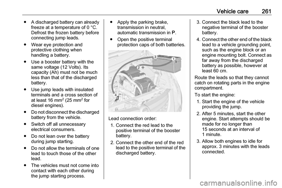
Lead connection order:
1. Connect the red lead to the positive terminal of the booster
battery.
2. Connect the other end of the red lead to the positive terminal of the
discharged battery.
3. Connect the black lead to the negative terminal of the booster
battery.
4. Connect the other end of the black
lead to a vehicle grounding point,
such as the engine block or an
engine mounting bolt. Connect as far away from the discharged
battery as possible, however at
least 60 cm.
Route the leads so that they cannot
catch on rotating parts in the engine
compartment.
To start the engine: 1. Start the engine of the vehicle providing the jump.
2. After 5 minutes, start the other engine. Start attempts should be
made for no longer than
15 seconds at an interval of
1 minute.
3. Allow both engines to idle for approx. 3 minutes with the leads
connected.