service indicator VAUXHALL ZAFIRA TOURER 2017 Owner's Manual
[x] Cancel search | Manufacturer: VAUXHALL, Model Year: 2017, Model line: ZAFIRA TOURER, Model: VAUXHALL ZAFIRA TOURER 2017Pages: 289, PDF Size: 8.91 MB
Page 97 of 289

Instruments and controls95Instruments and
controlsControls ....................................... 96
Steering wheel adjustment ........96
Steering wheel controls .............96
Heated steering wheel ...............96
Horn ........................................... 97
Windscreen wiper/washer .........97
Rear window wiper/washer .......99
Outside temperature ..................99
Clock ....................................... 100
Power outlets ........................... 101
Cigarette lighter .......................102
Ashtrays .................................. 102
Warning lights, gauges and indi‐ cators ......................................... 103
Instrument cluster ....................103
Speedometer ........................... 103
Odometer ................................ 103
Trip odometer .......................... 103
Tachometer ............................. 104
Fuel gauge .............................. 104
Fuel selector ............................ 105
Engine coolant temperature gauge ..................................... 106
Service display ........................ 106Control indicators ....................107
Turn signal ............................... 109
Seat belt reminder ...................110
Airbag and belt tensioners .......110
Airbag deactivation ..................111
Charging system .....................111
Malfunction indicator light ........111
Brake and clutch system .........111
Operate pedal .......................... 112
Electric parking brake ..............112
Electric parking brake fault ......112
Antilock brake system (ABS) ...112
Gear shifting ............................ 113
Power steering ........................ 113
Following distance ...................113
Lane departure warning ..........113
Electronic Stability Control off . 113
Electronic Stability Control and Traction Control system .........113
Traction Control system off .....113
Preheating ............................... 114
Diesel particle filter ..................114
AdBlue ..................................... 114
Tyre pressure monitoring system .................................... 114
Engine oil pressure ..................114
Low fuel ................................... 115
Immobiliser .............................. 115
Exterior light ............................ 115
High beam ............................... 115High beam assist.....................115
LED headlights ........................ 115
Fog light ................................... 115
Rear fog light ........................... 115
Cruise control .......................... 115
Adaptive cruise control ............116
Vehicle detected ahead ...........116
Speed limiter ........................... 116
Traffic sign assistant ................116
Door open ................................ 116
Information displays ...................116
Driver Information Centre ........116
Info display .............................. 121
Vehicle messages ......................122
Warning chimes .......................123
Battery voltage ........................ 123
Vehicle personalisation ..............124
Telematics service .....................127
OnStar ..................................... 127
Page 109 of 289

Instruments and controls107The system must be reset every time
the engine oil is changed to ensure
proper functionality. Seek the
assistance of a workshop.
Next service When the system has calculated that
engine oil life has been diminished,
Change Engine Oil Soon appears in
the Driver Information Centre. Have
engine oil and filter changed by a
workshop within one week or
300 miles (whichever occurs first).
Service information 3 257.
Control indicators
The control indicators described are
not present in all vehicles. The
description applies to all instrument
versions. Depending on the
equipment, the position of the control indicators may vary. When the
ignition is switched on, most control
indicators will illuminate briefly as a
functionality test.
The control indicator colours mean:red:danger, important reminderyellow:warning, information, faultgreen:confirmation of activationblue:confirmation of activationwhite:confirmation of activation
Page 114 of 289

112Instruments and controls9Warning
Stop. Do not continue your
journey. Consult a workshop.
Illuminates when the manual parking
brake is applied and ignition is
switched on 3 165.
Operate pedal - illuminates or flashes yellow.
Illuminates
Brake pedal must be depressed to release the electric parking brake
3 165
Clutch pedal must be depressed to
start the engine in Autostop mode.
Stop-start system 3 153.
Flashes
Clutch pedal must to be depressed for a main start of the engine 3 16,
3 151.
Additionally the operate pedal
message is indicated in the Driver
Information Centre 3 122.
Electric parking brake
m illuminates or flashes red.
Illuminates
Electric parking brake is applied
3 165.
Flashes
Electric parking brake is not fully
applied or released. Switch on
ignition, depress brake pedal and
attempt to reset the system by first
releasing and then applying the
electric parking brake. If m remains
flashing, do not drive and seek the
assistance of a workshop.
Electric parking brake fault j illuminates or flashes yellow.
Illuminates Electric parking brake is operating
with degraded performance 3 165.Flashes
Electric parking brake is in service mode. Stop vehicle, apply and
release the electric parking brake to
reset.9 Warning
Have the cause of the fault
remedied immediately by a
workshop.
Antilock brake system
(ABS)
u illuminates yellow.
Illuminates for a few seconds after the ignition is switched on. The system is
ready for operation when the control
indicator extinguishes.
If the control indicator does not
extinguish after a few seconds, or if it illuminates while driving, there is a
fault in the ABS. The brake system
remains operational but without ABS
regulation.
Antilock brake system 3 165.
Page 240 of 289

238Vehicle careIf w illuminates at lower temperatures
and extinguishes after some driving,
this could be an indicator for
approaching a low tyre pressure
condition. Check tyre pressure.
Vehicle messages 3 122.
If the tyre pressure must be reduced
or increased, switch off ignition.
Only mount wheels with pressure
sensors, otherwise the tyre pressure
will not be displayed and w
illuminates continuously.
A temporary spare wheel is not
equipped with pressure sensors. The
tyre pressure monitoring system is
not operational for these wheels.
Control indicator w illuminates. For
the further three wheels the system remains operational.
The use of commercially available
liquid tyre repair kits can impair the
function of the system. Factory-
approved repair kits can be used.
Operating electronic devices or being
close to facilities using similar wave
frequencies could disrupt the tyre
pressure monitoring system.Each time the tyres are replaced, tyre pressure monitoring system sensors
must be dismounted and serviced.
For the screwed sensor: replace
valve core and sealing ring. For
clipped sensor: replace complete
valve stem.
Vehicle loading status Adjust tyre pressure to load condition
according to the tyre information label or tyre pressure chart 3 272, and
select the appropriate setting in the Tyre load menu in the Driver
Information Centre 3 116. This
setting is the reference for the tyre
pressure warnings.
The Tyre load menu only appears if
the vehicle is at a standstill and the parking brake is applied. On vehicles
with automatic transmission the
selector lever has to be in P.
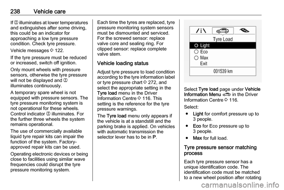
Select Tyre load page under Vehicle
Information Menu ? in the Driver
Information Centre 3 116.
Select: ● Light for comfort pressure up to
3 people.
● Eco for Eco pressure up to
3 people.
● Max for full load.
Tyre pressure sensor matching process
Each tyre pressure sensor has a
unique identification code. The
identification code must be matched
to a new wheel position after rotating
Page 279 of 289

Customer information277Translation of the original declaration
of conformity
Declaration of conformity according
to EC Directive 2006/42/EC
We declare that the product:
Product designation: Jack
Type/GM part number: 13348505,
13504504
is in compliance with the provisions of
Directive 2006/42/EC.
Applied technical standards:GMN9737:jackingGM 14337:standard equipment
jack – hardware
testsGMN5127:vehicle integrity –
hoisting and service station jackingGMW15005:standard equipment
jack and spare tire,
vehicle testISO TS 16949:quality
management
systemsThe signatory is authorised to
compile the technical documentation.
Rüsselsheim, 31st January 2014
signed by
Hans-Peter Metzger
Engineering Group Manager Chassis & Structure
Adam Opel AG
D-65423 Rüsselsheim
Collision damage repair
Paint thickness Due to production techniques, the
thickness of the paint can vary
between 50 and 400 µm.
Therefore, different paint thickness is
no indicator for a collision damage
repair.Software acknowledgement
Certain OnStar components include
libcurl and unzip software and other
third party software. Below are the
notices and licenses associated with
libcurl and unzip and for other third
party software please see http://
www.lg.com/global/support/
opensource/index.
libcurl Copyright and permission notice
Copyright (c) 1996 - 2010, Daniel
Stenberg,
All rights reserved.
Permission to use, copy, modify, and
distribute this software for any
purpose with or without fee is hereby
granted, provided that the above
copyright notice and this permission
notice appear in all copies.
The software is provided "as is",
without warranty of any kind, express
or implied, including but not limited to the warranties of merchantability,
fitness for a particular purpose and
noninfringement of third party rights.
In no event shall the authors or