Plug VAUXHALL ZAFIRA TOURER 2018 Owner's Manual
[x] Cancel search | Manufacturer: VAUXHALL, Model Year: 2018, Model line: ZAFIRA TOURER, Model: VAUXHALL ZAFIRA TOURER 2018Pages: 341, PDF Size: 9.89 MB
Page 103 of 341
Instruments and controls101Do not exceed the maximum power
consumption of 120 watts.
With ignition off, the power outlets are
deactivated. Additionally the power
outlets are deactivated in the event of
low vehicle battery voltage.
Electrical accessories that are
connected must comply with the
electromagnetic compatibility
requirements laid down in
DIN VDE 40 839.
Do not connect any current-delivering
accessories, e.g. electrical charging
devices or batteries.
Do not damage the outlet by using
unsuitable plugs.
Stop-start system 3 201.Cigarette lighter
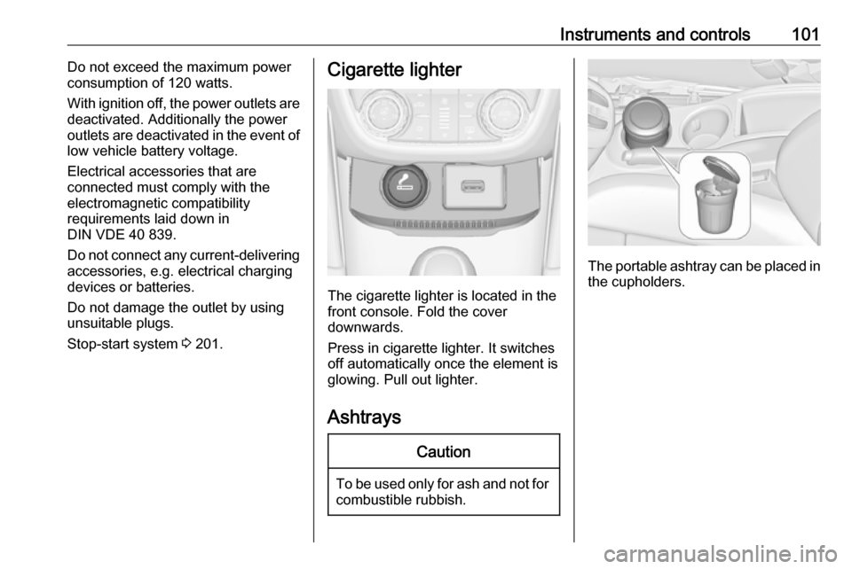
The cigarette lighter is located in the
front console. Fold the cover
downwards.
Press in cigarette lighter. It switches off automatically once the element is
glowing. Pull out lighter.
Ashtrays
Caution
To be used only for ash and not for combustible rubbish.
The portable ashtray can be placed inthe cupholders.
Page 137 of 341
Lighting135Light switch in position AUTO:
switching on front fog lights will switch
headlights on automatically.
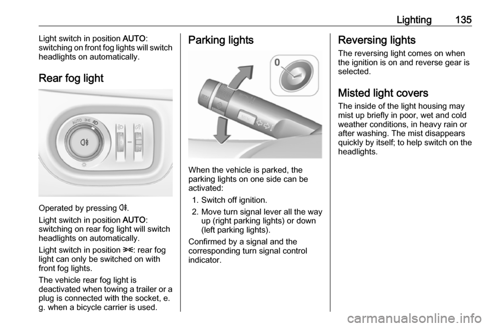
Rear fog light
Operated by pressing r
.
Light switch in position AUTO:
switching on rear fog light will switch
headlights on automatically.
Light switch in position 8: rear fog
light can only be switched on with
front fog lights.
The vehicle rear fog light is
deactivated when towing a trailer or a
plug is connected with the socket, e.
g. when a bicycle carrier is used.
Parking lights
When the vehicle is parked, the
parking lights on one side can be
activated:
1. Switch off ignition.
2. Move turn signal lever all the way up (right parking lights) or down
(left parking lights).
Confirmed by a signal and the
corresponding turn signal control
indicator.
Reversing lights
The reversing light comes on when
the ignition is on and reverse gear is
selected.
Misted light covers
The inside of the light housing may
mist up briefly in poor, wet and cold weather conditions, in heavy rain or
after washing. The mist disappears
quickly by itself; to help switch on the
headlights.
Page 239 of 341
Driving and operating237external noise sources may causethe system to fail to detect
obstacles.
Special attention must be paid to low obstacles which can damage
the lower part of the bumper.Caution
Performance of the system can be reduced when sensors are
covered, e.g. by ice or snow.
Performance of the parking assist
system can be reduced due to
heavy loading.
Special conditions apply if there
are taller vehicles in the vicinity
(e.g. off-road vehicles, mini vans,
vans). Object identification and correct distance indication in the
upper part of these vehicles
cannot be guaranteed.
Objects with a very small reflection
cross-section, e.g. objects of
narrow size or soft materials, may
not be detected by the system.
Parking assist systems do not
detect objects outside the
detection range.
Notice
The parking assist system
automatically detects factory-fitted
towing equipment. It is deactivated
when the connector is plugged in.
It is possible that the sensor detects a non-existing object (echo
disturbance) caused by external acoustical or mechanic
disturbances.
Notice
If engaging a forward gear and
exceeding a certain speed, the rear
parking assist will be deactivated
when the rear carrier system is
extended.
If engaging reverse gear first, the
parking assist will detect the rear
carrier system and provide a buzzing
sound. Press r briefly to
deactivate the parking assist.
Side blind spot alert
The side blind spot alert system
detects and reports objects on either
side of the vehicle, within a specified
"blind spot" zone. The system
displays a visual alert in each exterior
mirror, when detecting objects that
may not be visible in the interior and
exterior mirrors.
The system's sensors are located in
the bumper on the left and right side
of the vehicle.9 Warning
Side blind spot alert does not
replace driver vision.
The system does not detect:
● vehicles outside the side blind zones which may be rapidly
approaching
● pedestrians, cyclists or animals
Before changing a lane, always
check all mirrors, look over the
shoulder and use the turn signal.
Page 248 of 341
246Driving and operatingSome fuel does not contain sufficient
quantities of additive to keep fuel injectors and intake valves clean.
To make up for this lack of
detergency, add Fuel System
Treatment PLUS to the fuel tank at
every engine oil change or every
10,000 miles, whichever occurs first. It is available at your workshop.
Fuels containing oxygenates such as
ethers and ethanol, as well as
reformulated fuel, are available in
some cities. If these fuels comply with the previously described
specification, then they are
acceptable to use. However, E85
(85% ethanol) and other fuels
containing more than 15% ethanol
must be used only in FlexFuel
vehicles.Caution
Do not use fuel containing
methanol. It can corrode metal
parts in the fuel system and also
damage plastic and rubber parts.
This damage would not be
covered by the vehicle warranty.
Some fuels, mainly high octane
racing fuels, can contain an octane
enhancing additive called
methylcyclopentadienyl manganese
tricarbonyl (MMT). Do not use fuels or fuel additives with MMT as they can
reduce spark plug life and affect
emission control system
performance. The malfunction
indicator light Z may illuminate
3 111. If this occurs, seek the
assistance of a workshop.
Fuel for diesel engines Only use diesel fuel that complies
with EN 590 and which has a sulphur
concentration of max. 10 ppm.
Fuels with a biodiesel (compliant with
EN 14214) content of max. 7% by
volume may be used (e.g. named
B7).
If travelling in countries outside the
European Union, occasional use of
Euro-Diesel fuel with a sulphur
concentration below 50 ppm is
possible.Caution
Frequent usage of diesel fuel containing more than 15 ppm
sulphur will cause severe engine
damage.
Caution
Use of fuel that does not comply to EN 590 or similar can lead to
engine powerloss, increased wear
or engine damage and may affect
your warranty.
Do not use marine diesel oils, heating
oils, Aquazole and similar diesel-
water emulsions. Diesel fuels must
not be diluted with fuels for petrol
engines.
Low temperature operation At temperatures below 0° C, some
diesel products with biodiesel blends may clog, freeze or gel, which mayaffect the fuel supply system. Starting
and engine operation may not work
Page 257 of 341
Driving and operating255Rear axle loadWhen the trailer is coupled and the
towing vehicle fully loaded, the
permissible rear axle load (see
identification plate or vehicle
documents) may be exceeded by
60 kg , the gross vehicle weight rating
may be exceeded by 60 kg. If the
permissible rear axle load is
exceeded, a maximum speed of
60 mph applies.
Towing equipmentCaution
When operating without a trailer,
remove the coupling ball bar.
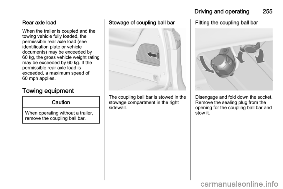
Stowage of coupling ball bar
The coupling ball bar is stowed in the
stowage compartment in the right
sidewall.
Fitting the coupling ball bar
Disengage and fold down the socket. Remove the sealing plug from the
opening for the coupling ball bar and
stow it.
Page 259 of 341
Driving and operating257Attach breakaway stopping cable to
eye.
Check that the coupling ball bar is
correctly installed
● Green marking on rotary knob must point towards green
marking on coupling ball bar.
● There must be no gap between the rotary handle and the
coupling ball bar.
● The coupling ball bar must be firmly engaged in the opening.
● The coupling ball bar must be locked and the key removed.9Warning
Towing a trailer is permitted only
when a coupling ball bar is fitted correctly. If the coupling ball bardoes not engage correctly, seekthe assistance of a workshop.
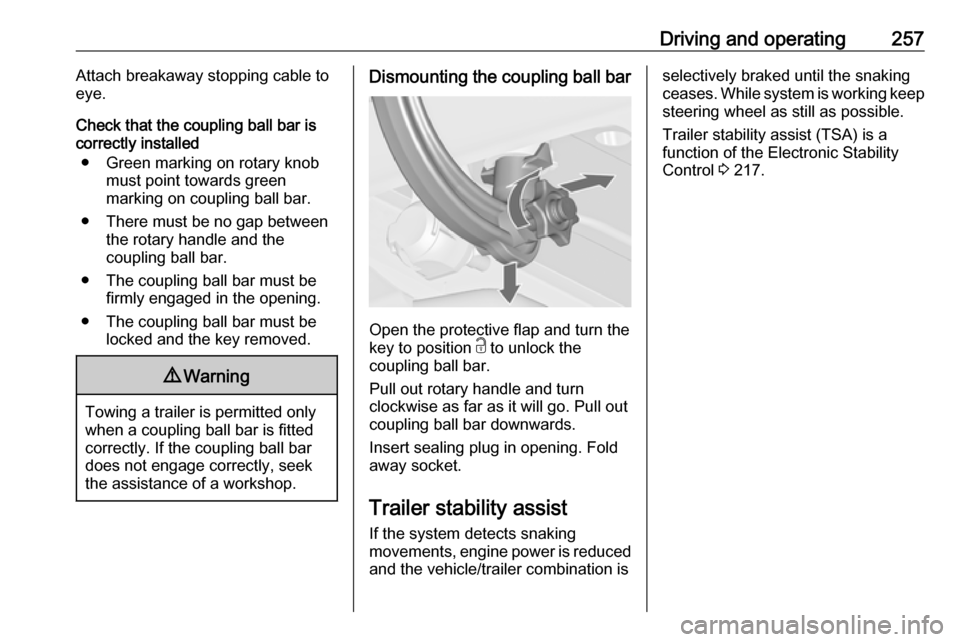
Dismounting the coupling ball bar
Open the protective flap and turn the
key to position c to unlock the
coupling ball bar.
Pull out rotary handle and turn
clockwise as far as it will go. Pull out coupling ball bar downwards.
Insert sealing plug in opening. Fold away socket.
Trailer stability assist
If the system detects snaking
movements, engine power is reduced
and the vehicle/trailer combination is
selectively braked until the snaking ceases. While system is working keep steering wheel as still as possible.
Trailer stability assist (TSA) is a
function of the Electronic Stability
Control 3 217.
Page 270 of 341
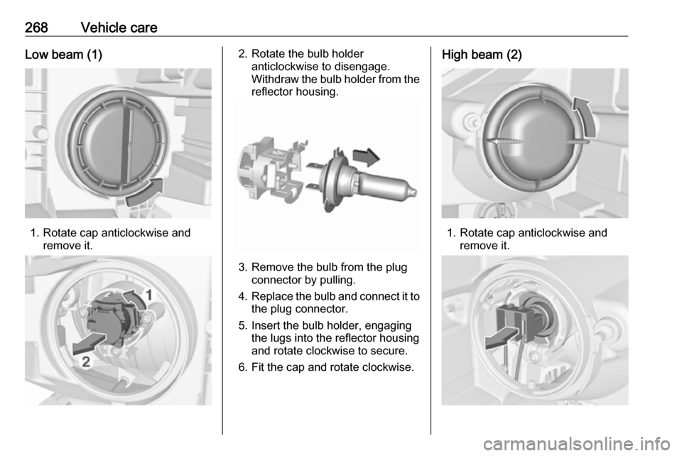
268Vehicle careLow beam (1)
1. Rotate cap anticlockwise andremove it.
2. Rotate the bulb holderanticlockwise to disengage.
Withdraw the bulb holder from the
reflector housing.
3. Remove the bulb from the plug connector by pulling.
4. Replace the bulb and connect it to
the plug connector.
5. Insert the bulb holder, engaging the lugs into the reflector housing
and rotate clockwise to secure.
6. Fit the cap and rotate clockwise.
High beam (2)
1. Rotate cap anticlockwise and remove it.
Page 271 of 341
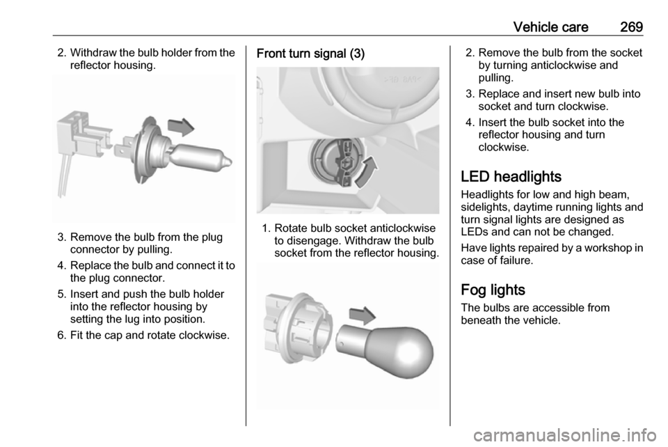
Vehicle care2692.Withdraw the bulb holder from the
reflector housing.
3. Remove the bulb from the plug connector by pulling.
4. Replace the bulb and connect it to
the plug connector.
5. Insert and push the bulb holder into the reflector housing by
setting the lug into position.
6. Fit the cap and rotate clockwise.
Front turn signal (3)
1. Rotate bulb socket anticlockwise to disengage. Withdraw the bulb
socket from the reflector housing.
2. Remove the bulb from the socket by turning anticlockwise and
pulling.
3. Replace and insert new bulb into socket and turn clockwise.
4. Insert the bulb socket into the reflector housing and turn
clockwise.
LED headlights
Headlights for low and high beam,
sidelights, daytime running lights and turn signal lights are designed as
LEDs and can not be changed.
Have lights repaired by a workshop in
case of failure.
Fog lights
The bulbs are accessible from
beneath the vehicle.
Page 272 of 341
270Vehicle care
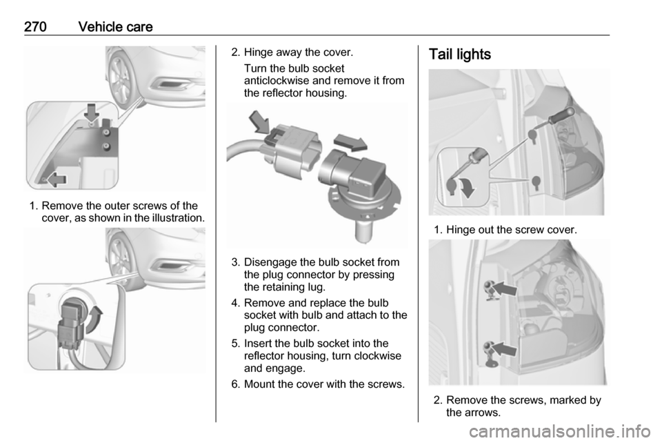
1. Remove the outer screws of thecover, as shown in the illustration.
2. Hinge away the cover.
Turn the bulb socket
anticlockwise and remove it from
the reflector housing.
3. Disengage the bulb socket from the plug connector by pressing
the retaining lug.
4. Remove and replace the bulb socket with bulb and attach to the
plug connector.
5. Insert the bulb socket into the reflector housing, turn clockwise
and engage.
6. Mount the cover with the screws.
Tail lights
1. Hinge out the screw cover.
2. Remove the screws, marked by the arrows.
Page 273 of 341
Vehicle care271
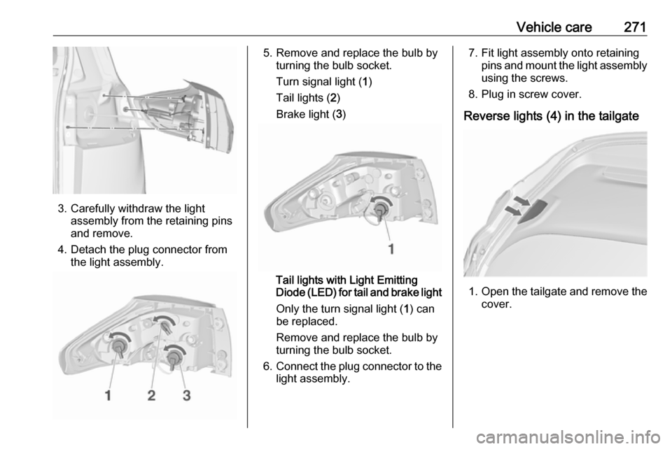
3. Carefully withdraw the lightassembly from the retaining pins
and remove.
4. Detach the plug connector from the light assembly.
5. Remove and replace the bulb by turning the bulb socket.
Turn signal light ( 1)
Tail lights ( 2)
Brake light ( 3)
Tail lights with Light Emitting
Diode (LED) for tail and brake light
Only the turn signal light ( 1) can
be replaced.
Remove and replace the bulb by
turning the bulb socket.
6. Connect the plug connector to the
light assembly.
7. Fit light assembly onto retaining pins and mount the light assembly
using the screws.
8. Plug in screw cover.
Reverse lights (4) in the tailgate
1. Open the tailgate and remove the
cover.