instrument panel VOLKSWAGEN BORA 1998 Service Manual
[x] Cancel search | Manufacturer: VOLKSWAGEN, Model Year: 1998, Model line: BORA, Model: VOLKSWAGEN BORA 1998Pages: 339, PDF Size: 2.35 MB
Page 149 of 339
Downloaded from www.Manualslib.com manuals search engine 01-145
Repair Manual,
Brake System, Repair
Group 45; Removing
and installing parts of
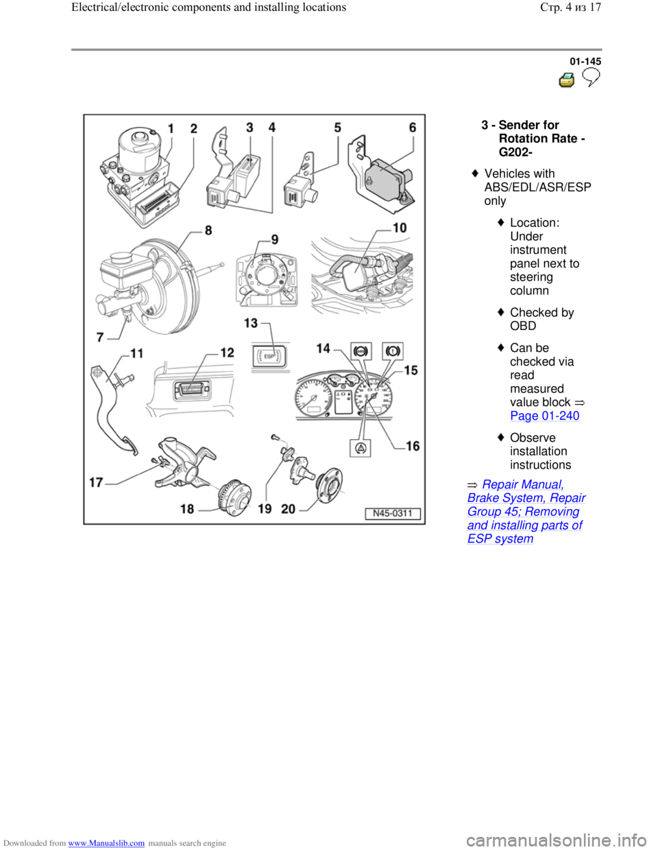
ESP system 3 -
Sender for
Rotation Rate -
G202-
Vehicles with
ABS/EDL/ASR/ESP
only
Location:
Under
instrument
panel next to
steering
column
Checked by
OBD
Can be
checked via
read
measured
value block
Page 01
-240
Observe
installation
instructions
Стр. 4из 17 Electrical/electronic components and installing locations
Page 150 of 339
Downloaded from www.Manualslib.com manuals search engine 01-146
Repair Manual,
Brake System, Repair
Group 45; Removing
and installing parts of
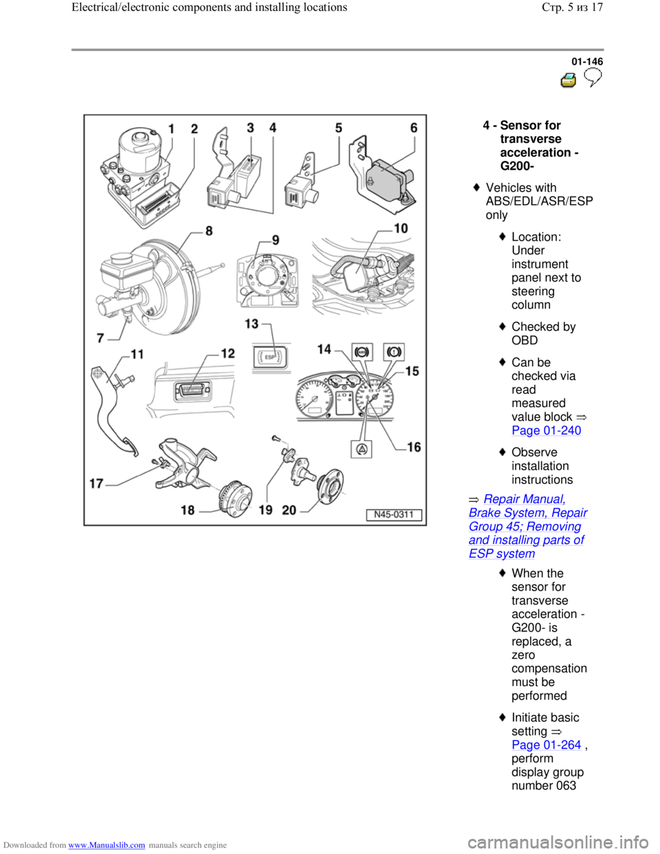
ESP system 4 -
Sensor for
transverse
acceleration -
G200-
Vehicles with
ABS/EDL/ASR/ESP
only
Location:
Under
instrument
panel next to
steering
column
Checked by
OBD
Can be
checked via
read
measured
value block
Page 01
-240
Observe
installation
instructions
When the
sensor for
transverse
acceleration -
G200- is
replaced, a
zero
compensation
must be
performed
Initiate basic
setting
Page 01
-264 ,
perform
display group
number 063
Стр. 5из 17 Electrical/electronic components and installing locations
Page 151 of 339
Downloaded from www.Manualslib.com manuals search engine 01-147
Repair Manual,
Brake System,
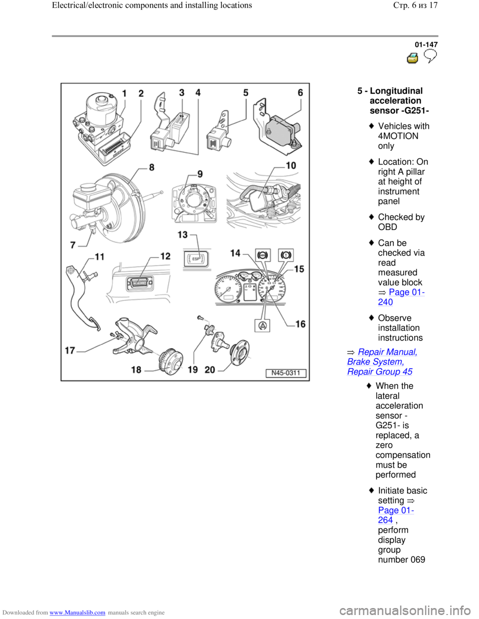
Repair Group 45 5 -
Longitudinal
acceleration
sensor -G251-
Vehicles with
4MOTION
only
Location: On
right A pillar
at height of
instrument
panel
Checked by
OBD
Can be
checked via
read
measured
value block
Page 01
-
240
Observe
installation
instructions
When the
lateral
acceleration
sensor -
G251- is
replaced, a
zero
compensation
must be
performed
Initiate basic
setting
Page 01
-
264 ,
perform
display
group
number 069
Стр. 6из 17 Electrical/electronic components and installing locations
Page 228 of 339
Downloaded from www.Manualslib.com manuals search engine 01-220
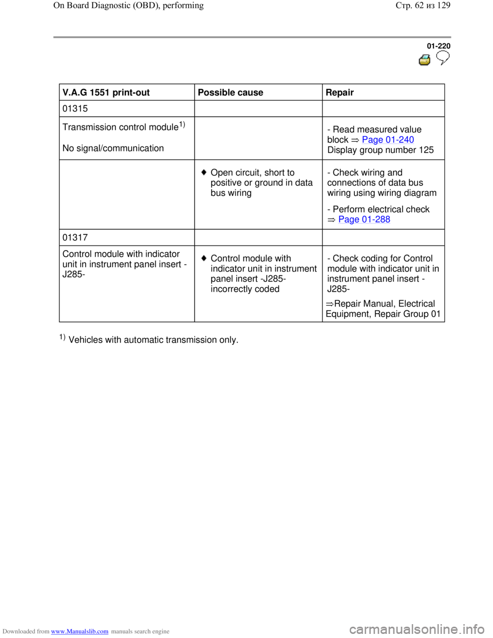
V.A.G 1551 print-out
Possible cause
Repair
01315
Transmission control module
1)
No signal/communication
- Read measured value
block Page 01
-240
Display group number 125
Open circuit, short to
positive or ground in data
bus wiring - Check wiring and
connections of data bus
wiring using wiring diagram
- Perform electrical check
Page 01
-288
01317
Control module with indicator
unit in instrument panel insert -
J285-
Control module with
indicator unit in instrument
panel insert -J285-
incorrectly coded
Repair Manual, Electrical
Equipment, Repair Group 01 - Check coding for Control
module with indicator unit in
instrument panel insert -
J285-
1) Vehicles with automatic transmission only.
Стр. 62из 129 On Board Diagnostic (OBD), performing
Page 316 of 339
Downloaded from www.Manualslib.com manuals search engine 01-308
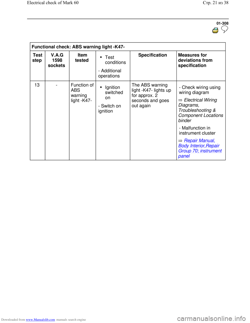
Functional check: ABS warning light -K47-
Test
step V.A.G
1598
sockets Item
tested
Test
conditions
- Additional
operations Specification
Measures for
deviations from
specification
13 - Function of
ABS
warning
light -K47-
Ignition
switched
on
- Switch on
ignition The ABS warning
light -K47- lights up
for approx. 2
seconds and goes
out again Electrical Wiring
Diagrams,
Troubleshooting &
Component Locations
binder
Repair Manual,
Body Interior,Repair
Group 70; instrument
panel - Check wiring using
wiring diagram
- Malfunction in
instrument cluster
Стр. 21из 38 Electrical check of Mark 60
Page 317 of 339
Downloaded from www.Manualslib.com manuals search engine 01-309
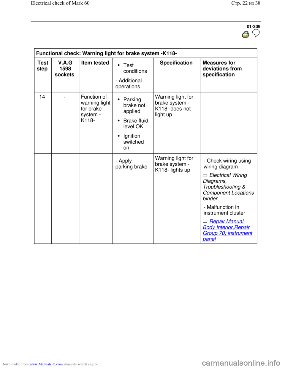
Functional check: Warning light for brake system -K118-
Test
step V.A.G
1598
sockets Item tested
Test
conditions
- Additional
operations Specification
Measures for
deviations from
specification
14 - Function of
warning light
for brake
system -
K118-
Parking
brake not
applied
Brake fluid
level OK
Ignition
switched
on Warning light for
brake system -
K118- does not
light up
- Apply
parking brake Warning light for
brake system -
K118- lights up
Electrical Wiring
Diagrams,
Troubleshooting &
Component Locations
binder
Repair Manual,
Body Interior,Repair
Group 70; instrument
panel - Check wiring using
wiring diagram
- Malfunction in
instrument cluster
Стр. 22из 38 Electrical check of Mark 60
Page 318 of 339
Downloaded from www.Manualslib.com manuals search engine 01-310
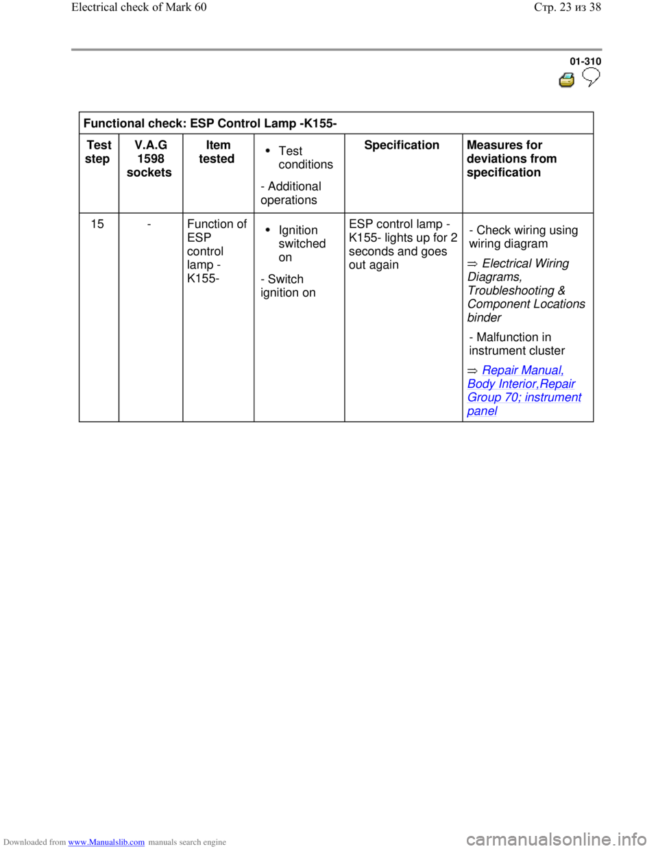
Functional check: ESP Control Lamp -K155-
Test
step V.A.G
1598
sockets Item
tested
Test
conditions
- Additional
operations Specification
Measures for
deviations from
specification
15 - Function of
ESP
control
lamp -
K155-
Ignition
switched
on
- Switch
ignition on ESP control lamp -
K155- lights up for 2
seconds and goes
out again Electrical Wiring
Diagrams,
Troubleshooting &
Component Locations
binder
Repair Manual,
Body Interior,Repair
Group 70; instrument
panel - Check wiring using
wiring diagram
- Malfunction in
instrument cluster
Стр. 23из 38 Electrical check of Mark 60
Page 320 of 339
Downloaded from www.Manualslib.com manuals search engine 01-312
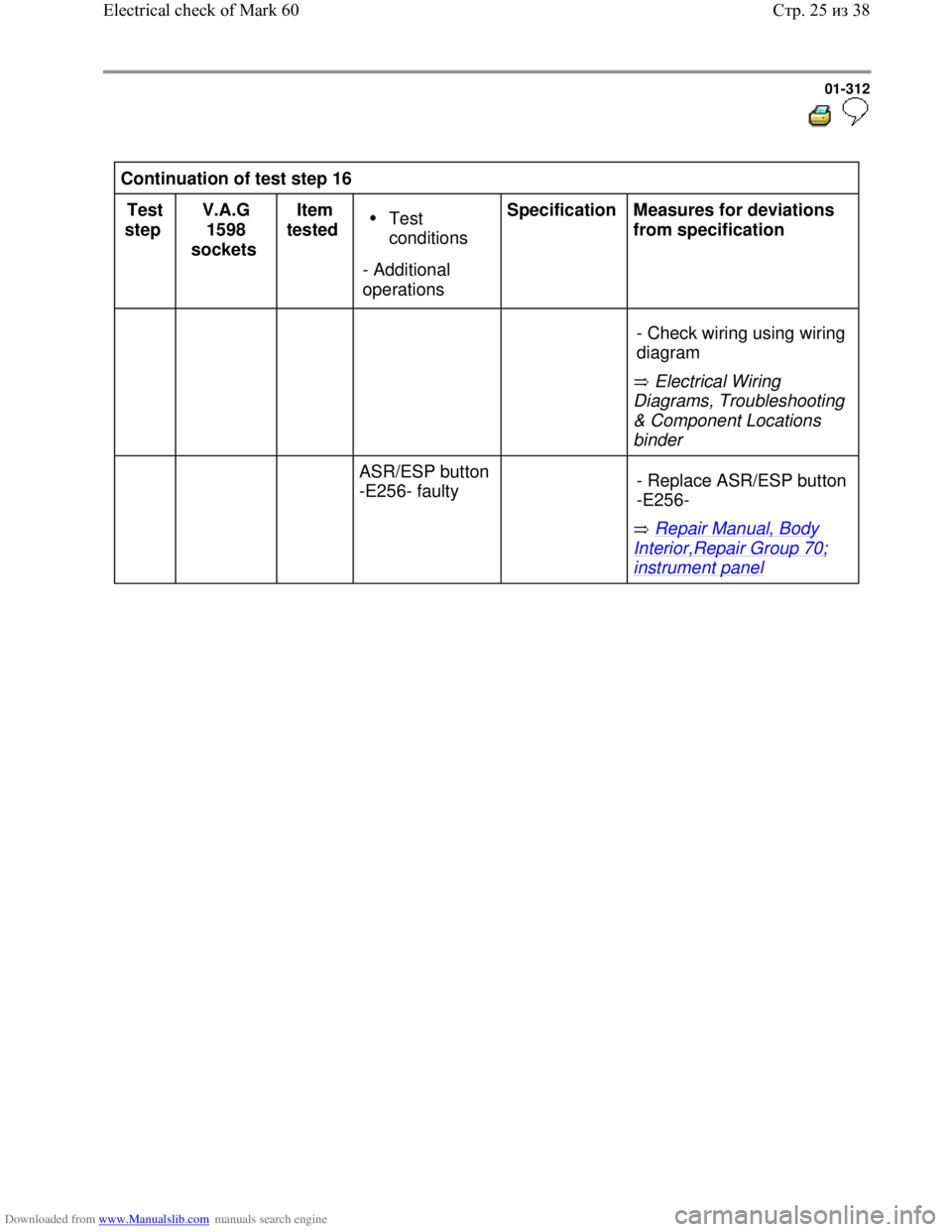
Continuation of test step 16
Test
step V.A.G
1598
sockets Item
tested
Test
conditions
- Additional
operations Specification
Measures for deviations
from specification
Electrical Wiring
Diagrams, Troubleshooting
& Component Locations
binder - Check wiring using wiring
diagram
ASR/ESP button
-E256- faulty
Repair Manual, Body
Interior,Repair Group 70;
instrument panel - Replace ASR/ESP button
-E256-
Стр. 25из 38 Electrical check of Mark 60