wheel VOLKSWAGEN BORA 1998 Service Manual
[x] Cancel search | Manufacturer: VOLKSWAGEN, Model Year: 1998, Model line: BORA, Model: VOLKSWAGEN BORA 1998Pages: 339, PDF Size: 2.35 MB
Page 14 of 339
Downloaded from www.Manualslib.com manuals search engine 01-13
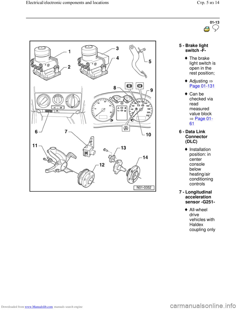
5 -
Brake light
switch -F-
The brake
light switch is
open in the
rest position;
Adjusting
Page 01
-131
Can be
checked via
read
measured
value block
Page 01
-
61
6 -
Data Link
Connector
(DLC)
Installation
position: in
center
console
below
heating/air
conditioning
controls
7 -
Longitudinal
acceleration
sensor -G251-
All-wheel
drive
vehicles with
Haldex
coupling only
Стр. 5из 14 Electrical/electronic components and locations
Page 16 of 339
Downloaded from www.Manualslib.com manuals search engine 01-15
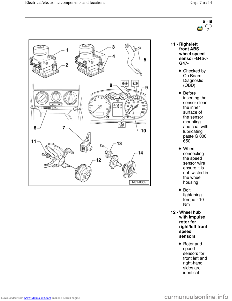
11 -
Right/left
front ABS
wheel speed
sensor -G45-/-
G47-
Checked by
On Board
Diagnostic
(OBD)
Before
inserting the
sensor clean
the inner
surface of
the sensor
mounting
and coat with
lubricating
paste G 000
650
When
connecting
the speed
sensor wire
ensure it is
not twisted in
the wheel
housing
Bolt
tightening
torque - 10
Nm
12 -
Wheel hub
with impulse
rotor for
right/left front
speed
sensors
Rotor and
speed
sensors for
front left and
right-hand
sides are
identical
Стр. 7из 14 Electrical/electronic components and locations
Page 17 of 339

Downloaded from www.Manualslib.com manuals search engine Repair Manual,
Suspension, Wheels,
Steering, Repair
Group 40
Removing
and installing
Стр. 8из 14 Electrical/electronic components and locations
Page 18 of 339
Downloaded from www.Manualslib.com manuals search engine 01-16
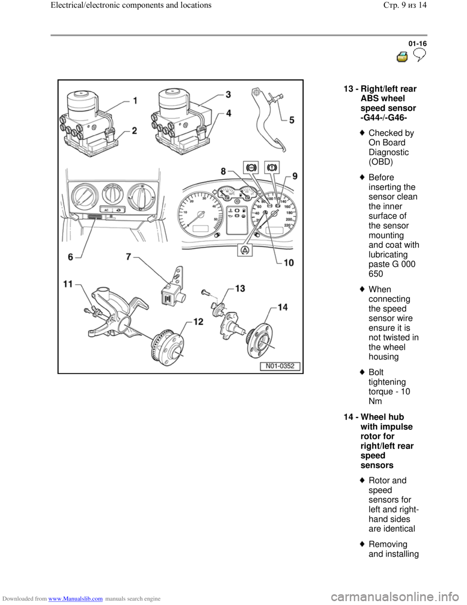
13 -
Right/left rear
ABS wheel
speed sensor
-G44-/-G46-
Checked by
On Board
Diagnostic
(OBD)
Before
inserting the
sensor clean
the inner
surface of
the sensor
mounting
and coat with
lubricating
paste G 000
650
When
connecting
the speed
sensor wire
ensure it is
not twisted in
the wheel
housing
Bolt
tightening
torque - 10
Nm
14 -
Wheel hub
with impulse
rotor for
right/left rear
speed
sensors
Rotor and
speed
sensors for
left and right-
hand sides
are identical
Removing
and installing
Стр. 9из 14 Electrical/electronic components and locations
Page 19 of 339

Downloaded from www.Manualslib.com manuals search engine Repair Manual,
Suspension, Wheels,
Steering, Repair
Group 42
Стр. 10из 14 Electrical/electronic components and locations
Page 22 of 339
Downloaded from www.Manualslib.com manuals search engine 01-19
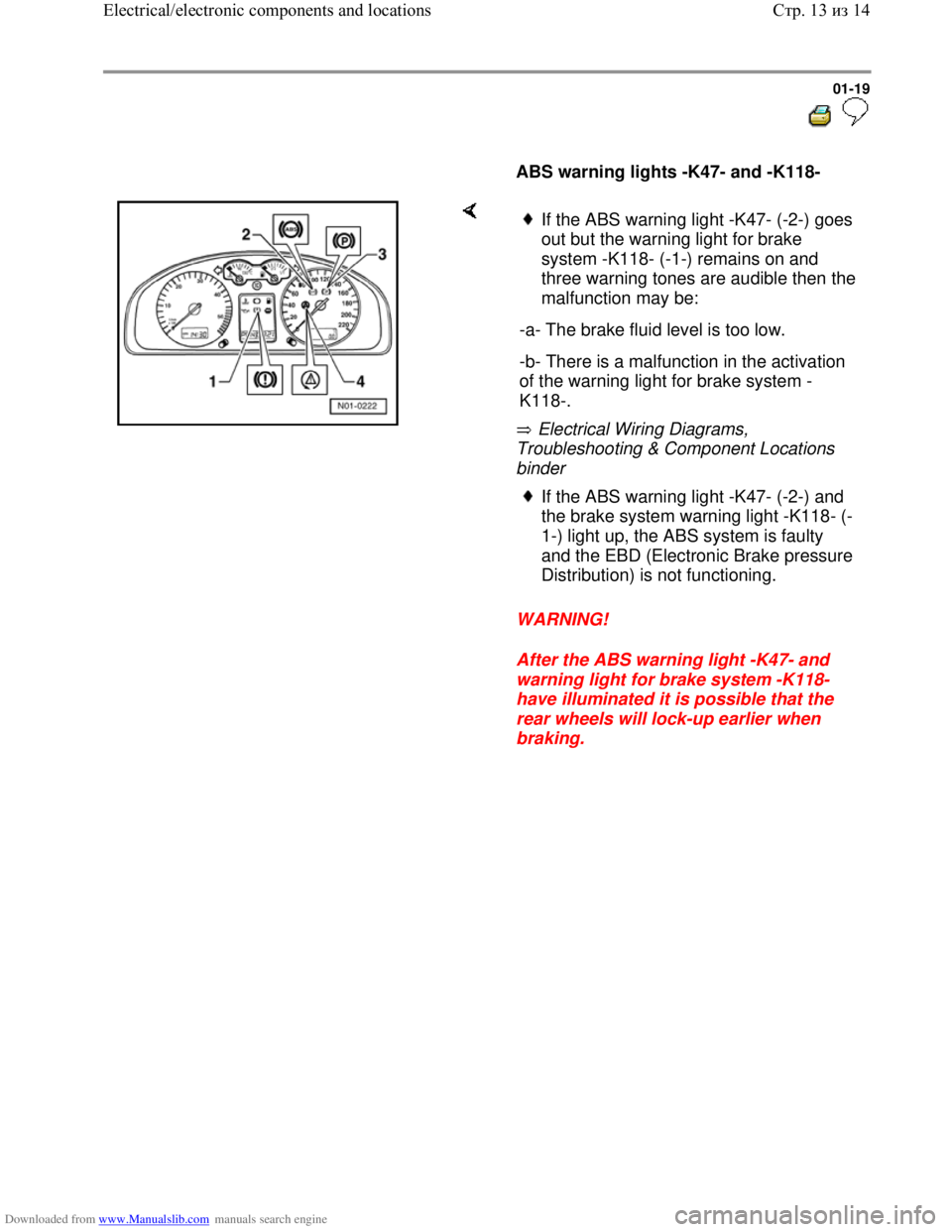
ABS warning lights -K47- and -K118-
Electrical Wiring Diagrams,
Troubleshooting & Component Locations
binder
WARNING!
After the ABS warning light -K47- and
warning light for brake system -K118-
have illuminated it is possible that the
rear wheels will lock-up earlier when
braking.
If the ABS warning light -K47- (-2-) goes
out but the warning light for brake
system -K118- (-1-) remains on and
three warning tones are audible then the
malfunction may be:
-a- The brake fluid level is too low.
-b- There is a malfunction in the activation
of the warning light for brake system -
K118-.
If the ABS warning light -K47- (-2-) and
the brake system warning light -K118- (-
1-) light up, the ABS system is faulty
and the EBD (Electronic Brake pressure
Distribution) is not functioning.
Стр. 13из 14 Electrical/electronic components and locations
Page 25 of 339
Downloaded from www.Manualslib.com manuals search engine 01-22
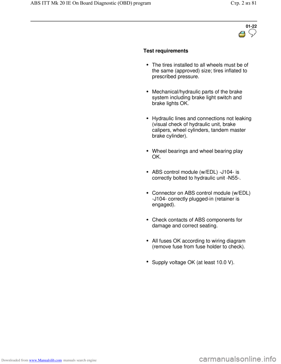
Test requirements
The tires installed to all wheels must be of
the same (approved) size; tires inflated to
prescribed pressure.
Mechanical/hydraulic parts of the brake
system including brake light switch and
brake lights OK.
Hydraulic lines and connections not leaking
(visual check of hydraulic unit, brake
calipers, wheel cylinders, tandem master
brake cylinder).
Wheel bearings and wheel bearing play
OK.
ABS control module (w/EDL) -J104- is
correctly bolted to hydraulic unit -N55-.
Connector on ABS control module (w/EDL)
-J104- correctly plugged-in (retainer is
engaged).
Check contacts of ABS components for
damage and correct seating.
All fuses OK according to wiring diagram
(remove fuse from fuse holder to check).
Supply voltage OK (at least 10.0 V).
Стр. 2из 81 ABS ITT Mk 20 IE On Board Diagnostic (OBD) program
Page 40 of 339
Downloaded from www.Manualslib.com manuals search engine
01-37
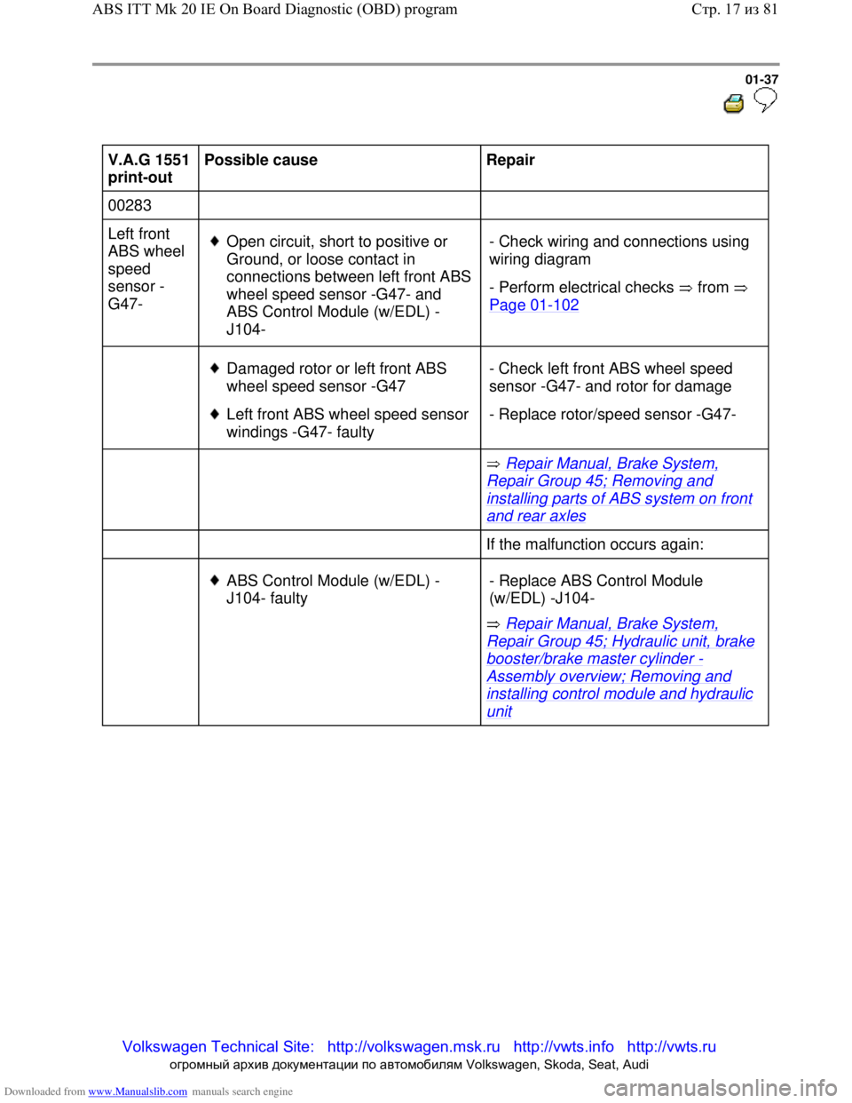
V.A.G 1551
print-out Possible cause
Repair
00283
Left front
ABS wheel
speed
sensor -
G47-
Open circuit, shor
t to positive or
Ground, or loose contact in
connections betwe en left front ABS
wheel speed sens or -G47- and
ABS Control Mo dule (w/EDL) -
J104- - Check wiring and
connections using
wiring diagram
- Perform electrical checks from
Page 01
-102
Damaged rotor or left front ABS
wheel speed sensor -G47
Left front ABS whee l speed sensor
windings -G47- faulty - Check left front
ABS wheel speed
sensor -G47- and rotor for damage
- Replace rotor/speed sensor -G47-
Repair Manual, Brake System,
Repair Group 45; Removing and
installing parts of ABS system on front
and rear axles
If the malfuncti on occurs again:
ABS Control Module (w/EDL) -
J104- faulty
Repair Manual, Brake System,
Repair Group 45; Hydraulic unit, brake
booster/brake master cylinder -
Assembly overview; Removing and
installing control mo dule and hydraulic
unit
- Replace ABS Control Module
(w/EDL) -J104-
Стр. 17
из 81
ABS ITT Mk 20 IE On Board Diagnostic (OBD) program
Volkswagen Technical Site: http://v olkswagen.msk.ru http://vwts.info http://vwts.ru
огромный архив документации по автомобилям Volkswagen, Skoda, Seat, Audi
Page 41 of 339
Downloaded from www.Manualslib.com manuals search engine 01-38
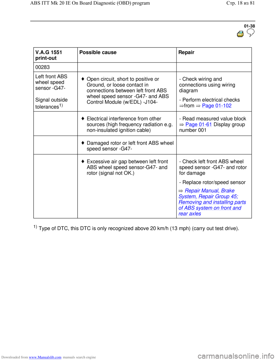
V.A.G 1551
print-out Possible cause
Repair
00283
Left front ABS
wheel speed
sensor -G47-
Signal outside
tolerances
1)
Open circuit, short to positive or
Ground, or loose contact in
connections between left front ABS
wheel speed sensor -G47- and ABS
Control Module (w/EDL) -J104- - Check wiring and
connections using wiring
diagram
- Perform electrical checks
from Page 01
-102
Electrical interference from other
sources (high frequency radiation e.g.
non-insulated ignition cable) - Read measured value block
Page 01
-61 Display group
number 001
Damaged rotor or left front ABS wheel
speed sensor -G47-
Excessive air gap between left front
ABS wheel speed sensor-G47- and
rotor (signal not OK.)
Repair Manual, Brake
System, Repair Group 45;
Removing and installing parts
of ABS system on front and
rear axles - Check left front ABS wheel
speed sensor -G47- and rotor
for damage
- Replace rotor/speed sensor
1) Type of DTC, this DTC is only recognized above 20 km/h (13 mph) (carry out test drive).
Стр. 18из 81 ABS ITT Mk 20 IE On Board Diagnostic (OBD) program
Page 42 of 339
Downloaded from www.Manualslib.com manuals search engine 01-39
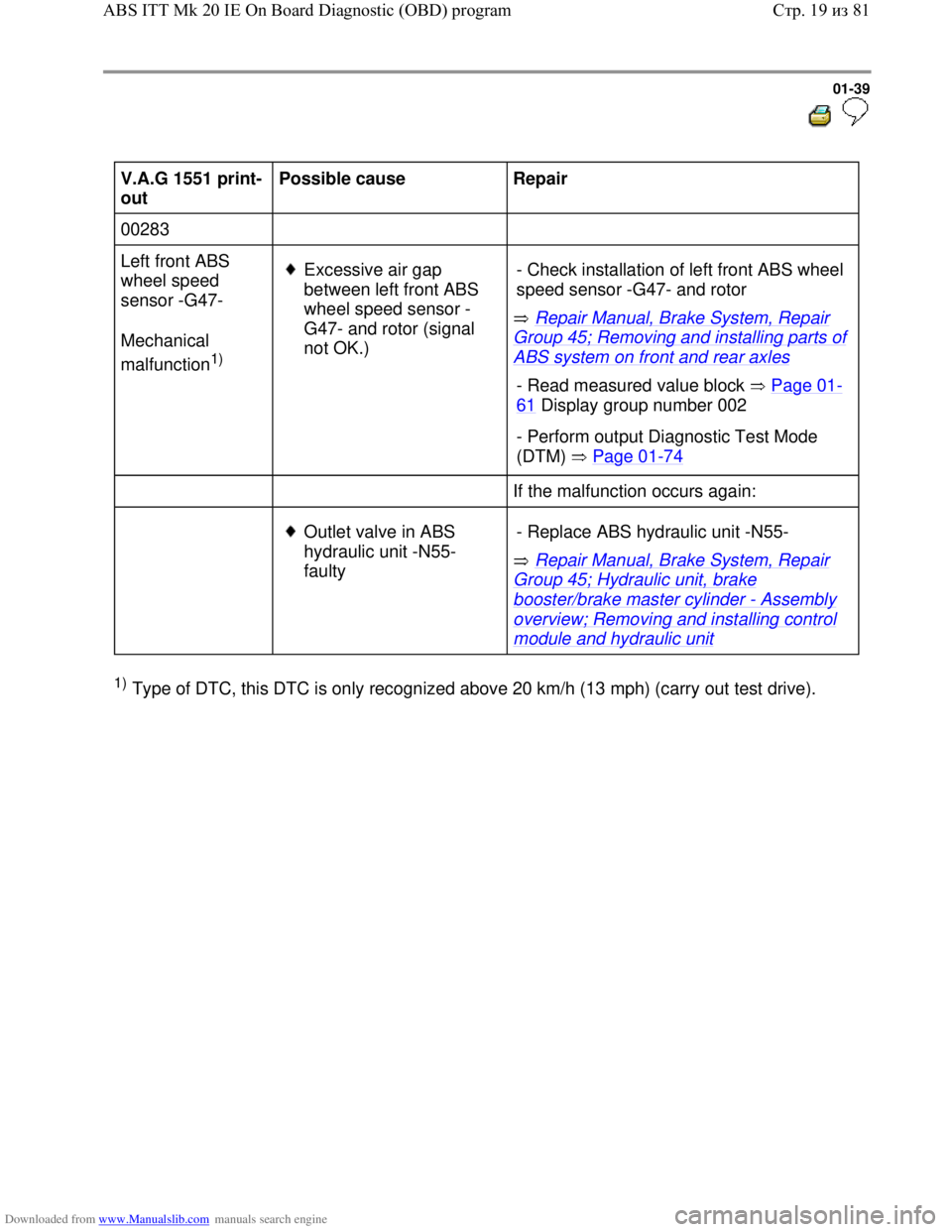
V.A.G 1551 print-
out Possible cause
Repair
00283
Left front ABS
wheel speed
sensor -G47-
Mechanical
malfunction
1)
Excessive air gap
between left front ABS
wheel speed sensor -
G47- and rotor (signal
not OK.) Repair Manual, Brake System, Repair
Group 45; Removing and installing parts of
ABS system on front and rear axles - Check installation of left front ABS wheel
speed sensor -G47- and rotor
- Read measured value block Page 01-
61 Display group number 002
- Perform output Diagnostic Test Mode
(DTM) Page 01
-74
If the malfunction occurs again:
Outlet valve in ABS
hydraulic unit -N55-
faulty Repair Manual, Brake System, Repair
Group 45; Hydraulic unit, brake
booster/brake master cylinder - Assembly
overview; Removing and installing control
module and hydraulic unit - Replace ABS hydraulic unit -N55-
1) Type of DTC, this DTC is only recognized above 20 km/h (13 mph) (carry out test drive).
Стр. 19из 81 ABS ITT Mk 20 IE On Board Diagnostic (OBD) program