brake sensor VOLKSWAGEN CORRADO 1990 User Guide
[x] Cancel search | Manufacturer: VOLKSWAGEN, Model Year: 1990, Model line: CORRADO, Model: VOLKSWAGEN CORRADO 1990Pages: 906, PDF Size: 6.56 MB
Page 381 of 906

ABBREVIATIONS
Article Text (p. 4)
1990 Volkswagen Corrado
For Volkswagen Technical Site: http://vw.belcom.ru
Copyright © 1998 Mitchell Repair Information Company, LLC
Thursday, March 23, 2000 09:42PM³DERM ³Diagnostic Energy Reserve Module ³
³DFI
³Digital Fuel Injection ³
³DIC
³Driver Information Center ³
³DIS
³Direct Ignition System ³
³DIS
³Distributorless Ignition System ³
³DIST
³Distribution ³
³DISTR
³Distributor ³
³DK BLU
³Dark Blue ³
³DK GRN
³Dark Green ³
³DME
³Digital Motor Electronics (Motronic System) ³
³DOHC
³Double Overhead Cam ³
³DOT
³Department of Transportation ³
³DP
³Dashpot ³
³DRB-II
³Diagnostic Readout Box ³
³DVOM
³Digital Volt/Ohm Meter (see VOM) ³
³Def.
³Defogger or Defroster ³
³Def.
³Defrost ³
³Defog.
³Defogger ³
³Diag.
³Diagnostic ³
³Dist.
³Distributor or Distribution ³
³Dr.
³Door ³
ÀÄÄÄÄÄÄÄÄÄÄÄÄÄÄÄÄÄÁÄÄÄÄÄÄÄÄÄÄÄÄÄÄÄÄÄÄÄÄÄÄÄÄÄÄÄÄÄÄÄÄÄÄÄÄÄÄÄÄÄÄÄÄÄÄÄÄÄÄÙ "E" ABBREVIATION TABLE
"E" ABBREVIATION TABLE
ÚÄÄÄÄÄÄÄÄÄÄÄÄÄÄÄÄÄÂÄÄÄÄÄÄÄÄÄÄÄÄÄÄÄÄÄÄÄÄÄÄÄÄÄÄÄÄÄÄÄÄÄÄÄÄÄÄÄÄÄÄÄÄÄÄÄÄÄÄ¿
³ABBREVIATION
³DEFINITION ³
ÃÄÄÄÄÄÄÄÄÄÄÄÄÄÄÄÄÄÅÄÄÄÄÄÄÄÄÄÄÄÄÄÄÄÄÄÄÄÄÄÄÄÄÄÄÄÄÄÄÄÄÄÄÄÄÄÄÄÄÄÄÄÄÄÄÄÄÄÄ´
³EAC
³Electric Assist Choke ³
³EACV
³Electric Air Control Valve ³
³EBCM
³Electronic Brake Control Module ³
³ECA
³Electronic Control Assembly ³
³ECAT
³Electronically Controlled Automatic Transaxle ³
³ECM
³Electronic Control Module ³
³ECT
³Engine Coolant Temperature Sensor ³
³ECU
³Electronic Control Unit or Engine Control Unit ³
³EDF
³Electric Drive Fan relay assembly ³
³EDIS
³Electronic Distributorless Ignition System ³
³EEC
³Electronic Engine Control ³
³EECS
³Evaporative Emission Control System ³
³EEPROM
³Electronically Erasable PROM ³
³EFE
³Early Fuel Evaporation ³
³EFI
³Electronic Fuel Injection ³
³EGO
³Exhaust Gas Oxygen sensor (see HEGO) ³
³EGR
³Exhaust Gas Recirculation system ³
³EGRC
³EGR Control solenoid or system ³
³EGRV
³EGR Vent solenoid or system ³
³EMR
³Emission Maintenance Reminder Module ³
³ESA
³Electronic Spark Advance ³
³ESC
³Electronic Spark Control ³
³EST
³Electronic Spark Timing ³
Page 387 of 906

ABBREVIATIONS
Article Text (p. 10)
1990 Volkswagen Corrado
For Volkswagen Technical Site: http://vw.belcom.ru
Copyright © 1998 Mitchell Repair Information Company, LLC
Thursday, March 23, 2000 09:42PM
"Q" ABBREVIATION TABLEÚÄÄÄÄÄÄÄÄÄÄÄÄÄÄÄÄÄÂÄÄÄÄÄÄÄÄÄÄÄÄÄÄÄÄÄÄÄÄÄÄÄÄÄÄÄÄÄÄÄÄÄÄÄÄÄÄÄÄÄÄÄÄÄÄÄÄÄÄ¿
³ABBREVIATION
³DEFINITION ³
ÃÄÄÄÄÄÄÄÄÄÄÄÄÄÄÄÄÄÅÄÄÄÄÄÄÄÄÄÄÄÄÄÄÄÄÄÄÄÄÄÄÄÄÄÄÄÄÄÄÄÄÄÄÄÄÄÄÄÄÄÄÄÄÄÄÄÄÄÄ´
³Qts.
³Quarts ³
ÀÄÄÄÄÄÄÄÄÄÄÄÄÄÄÄÄÄÁÄÄÄÄÄÄÄÄÄÄÄÄÄÄÄÄÄÄÄÄÄÄÄÄÄÄÄÄÄÄÄÄÄÄÄÄÄÄÄÄÄÄÄÄÄÄÄÄÄÄÙ "R" ABBREVIATION TABLE
"R" ABBREVIATION TABLE
ÚÄÄÄÄÄÄÄÄÄÄÄÄÄÄÄÄÄÂÄÄÄÄÄÄÄÄÄÄÄÄÄÄÄÄÄÄÄÄÄÄÄÄÄÄÄÄÄÄÄÄÄÄÄÄÄÄÄÄÄÄÄÄÄÄÄÄÄÄ¿
³ABBREVIATION
³DEFINITION ³
ÃÄÄÄÄÄÄÄÄÄÄÄÄÄÄÄÄÄÅÄÄÄÄÄÄÄÄÄÄÄÄÄÄÄÄÄÄÄÄÄÄÄÄÄÄÄÄÄÄÄÄÄÄÄÄÄÄÄÄÄÄÄÄÄÄÄÄÄÄ´
³RABS
³Rear Anti-Lock Brake System ³
³RAC
³Remote Accessory Control ³
³RAM
³Random Access Memory ³
³RAP
³Retained Accessory Power ³
³RECIRC
³Recirculation ³
³RED
³Red ³
³RH
³Right Hand ³
³ROM
³Read Only Memory ³
³RPM
³Revolutions Per Minute ³
³RVB
³Rear Vacuum Break ³
³RWAL
³Rear Wheel Anti-Lock Brake ³
³RWD
³Rear Wheel Drive ³
³Recirc.
³Recirculate or Recirculation ³
³Reg.
³Regulator ³
³Rly.
³Relay ³
ÀÄÄÄÄÄÄÄÄÄÄÄÄÄÄÄÄÄÁÄÄÄÄÄÄÄÄÄÄÄÄÄÄÄÄÄÄÄÄÄÄÄÄÄÄÄÄÄÄÄÄÄÄÄÄÄÄÄÄÄÄÄÄÄÄÄÄÄÄÙ "S" ABBREVIATION TABLE
"S" ABBREVIATION TABLE
ÚÄÄÄÄÄÄÄÄÄÄÄÄÄÄÄÄÄÂÄÄÄÄÄÄÄÄÄÄÄÄÄÄÄÄÄÄÄÄÄÄÄÄÄÄÄÄÄÄÄÄÄÄÄÄÄÄÄÄÄÄÄÄÄÄÄÄÄÄ¿
³ABBREVIATION
³DEFINITION ³
ÃÄÄÄÄÄÄÄÄÄÄÄÄÄÄÄÄÄÅÄÄÄÄÄÄÄÄÄÄÄÄÄÄÄÄÄÄÄÄÄÄÄÄÄÄÄÄÄÄÄÄÄÄÄÄÄÄÄÄÄÄÄÄÄÄÄÄÄÄ´
³SBC
³Single Bed Converter ³
³SBEC
³Single Board Engine Controller ³
³SC
³Super Charged ³
³SCC
³Spark Control Computer ³
³SCS
³Air Suction Control Solenoid ³
³SDM
³Supplemental Restraint System Diagnostic Module ³
³SDU
³SRS Diagnostic Unit ³
³SEN
³Sensor ³
³SES
³Service Engine Soon ³
³SFI
³Sequential (Port) Fuel Injection ³
³SIG RTN
³Signal Return circuit ³
³SIL
³Shift Indicator Light ³
³SIR
³Supplemental Inflatable Restraint ³
³SMEC
³Single Module Engine Controller ³
³SOHC
³Single Overhead Cam ³
Page 390 of 906
ABBREVIATIONS
Article Text
1990 Volkswagen Corrado
For Volkswagen Technical Site: http://vw.belcom.ru
Copyright © 1998 Mitchell Repair Information Company, LLC
Thursday, March 23, 2000 09:42PM
ARTICLE BEGINNING
GENERAL INFORMATION
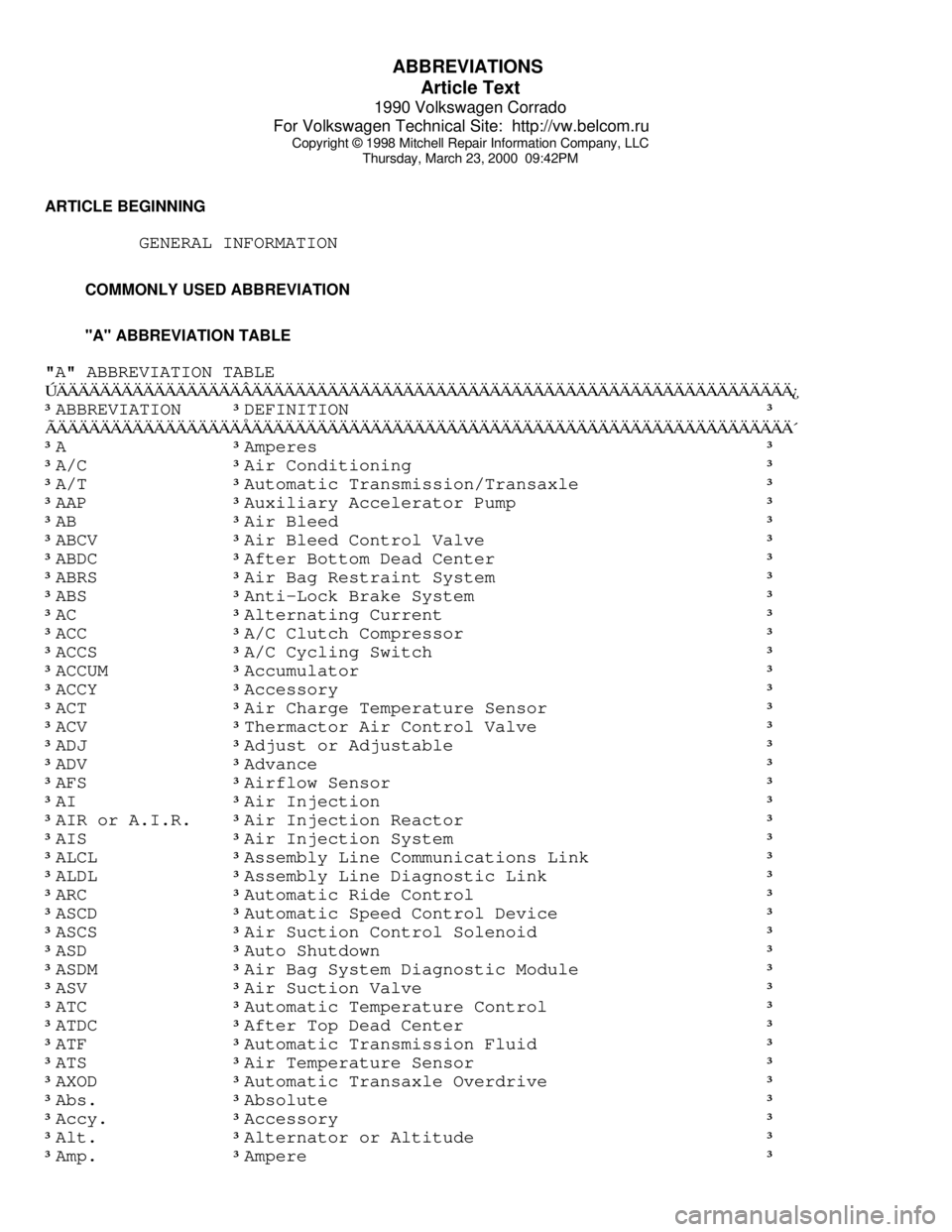
COMMONLY USED ABBREVIATION
"A" ABBREVIATION TABLE
"A" ABBREVIATION TABLEÚÄÄÄÄÄÄÄÄÄÄÄÄÄÄÄÄÄÂÄÄÄÄÄÄÄÄÄÄÄÄÄÄÄÄÄÄÄÄÄÄÄÄÄÄÄÄÄÄÄÄÄÄÄÄÄÄÄÄÄÄÄÄÄÄÄÄÄÄ¿
³ABBREVIATION
³DEFINITION ³
ÃÄÄÄÄÄÄÄÄÄÄÄÄÄÄÄÄÄÅÄÄÄÄÄÄÄÄÄÄÄÄÄÄÄÄÄÄÄÄÄÄÄÄÄÄÄÄÄÄÄÄÄÄÄÄÄÄÄÄÄÄÄÄÄÄÄÄÄÄ´
³A
³Amperes ³
³A/C
³Air Conditioning ³
³A/T
³Automatic Transmission/Transaxle ³
³AAP
³Auxiliary Accelerator Pump ³
³AB
³Air Bleed ³
³ABCV
³Air Bleed Control Valve ³
³ABDC
³After Bottom Dead Center ³
³ABRS
³Air Bag Restraint System ³
³ABS
³Anti-Lock Brake System ³
³AC
³Alternating Current ³
³ACC
³A/C Clutch Compressor ³
³ACCS
³A/C Cycling Switch ³
³ACCUM
³Accumulator ³
³ACCY
³Accessory ³
³ACT
³Air Charge Temperature Sensor ³
³ACV
³Thermactor Air Control Valve ³
³ADJ
³Adjust or Adjustable ³
³ADV
³Advance ³
³AFS
³Airflow Sensor ³
³AI
³Air Injection ³
³AIR or A.I.R.
³Air Injection Reactor ³
³AIS
³Air Injection System ³
³ALCL
³Assembly Line Communications Link ³
³ALDL
³Assembly Line Diagnostic Link ³
³ARC
³Automatic Ride Control ³
³ASCD
³Automatic Speed Control Device ³
³ASCS
³Air Suction Control Solenoid ³
³ASD
³Auto Shutdown ³
³ASDM
³Air Bag System Diagnostic Module ³
³ASV
³Air Suction Valve ³
³ATC
³Automatic Temperature Control ³
³ATDC
³After Top Dead Center ³
³ATF
³Automatic Transmission Fluid ³
³ATS
³Air Temperature Sensor ³
³AXOD
³Automatic Transaxle Overdrive ³
³Abs.
³Absolute ³
³Accy.
³Accessory ³
³Alt.
³Alternator or Altitude ³
³Amp.
³Ampere ³
Page 391 of 906
ABBREVIATIONS
Article Text (p. 2)
1990 Volkswagen Corrado
For Volkswagen Technical Site: http://vw.belcom.ru
Copyright © 1998 Mitchell Repair Information Company, LLC
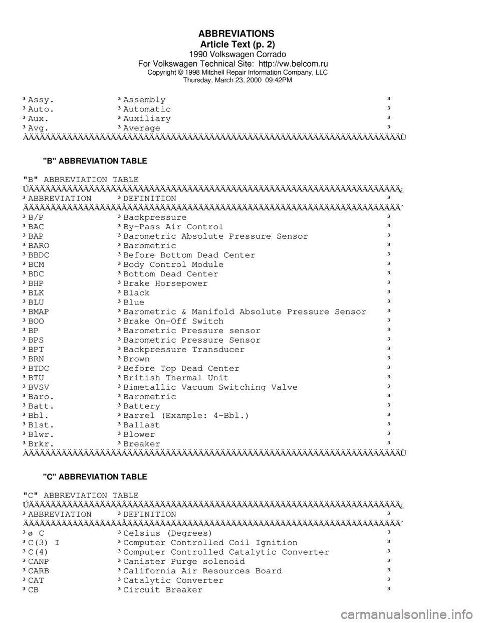
Thursday, March 23, 2000 09:42PM³Assy. ³Assembly ³
³Auto.
³Automatic ³
³Aux.
³Auxiliary ³
³Avg.
³Average ³
ÀÄÄÄÄÄÄÄÄÄÄÄÄÄÄÄÄÄÁÄÄÄÄÄÄÄÄÄÄÄÄÄÄÄÄÄÄÄÄÄÄÄÄÄÄÄÄÄÄÄÄÄÄÄÄÄÄÄÄÄÄÄÄÄÄÄÄÄÄÙ "B" ABBREVIATION TABLE
"B" ABBREVIATION TABLE
ÚÄÄÄÄÄÄÄÄÄÄÄÄÄÄÄÄÄÂÄÄÄÄÄÄÄÄÄÄÄÄÄÄÄÄÄÄÄÄÄÄÄÄÄÄÄÄÄÄÄÄÄÄÄÄÄÄÄÄÄÄÄÄÄÄÄÄÄÄ¿
³ABBREVIATION
³DEFINITION ³
ÃÄÄÄÄÄÄÄÄÄÄÄÄÄÄÄÄÄÅÄÄÄÄÄÄÄÄÄÄÄÄÄÄÄÄÄÄÄÄÄÄÄÄÄÄÄÄÄÄÄÄÄÄÄÄÄÄÄÄÄÄÄÄÄÄÄÄÄÄ´
³B/P
³Backpressure ³
³BAC
³By-Pass Air Control ³
³BAP
³Barometric Absolute Pressure Sensor ³
³BARO
³Barometric ³
³BBDC
³Before Bottom Dead Center ³
³BCM
³Body Control Module ³
³BDC
³Bottom Dead Center ³
³BHP
³Brake Horsepower ³
³BLK
³Black ³
³BLU
³Blue ³
³BMAP
³Barometric & Manifold Absolute Pressure Sensor ³
³BOO
³Brake On-Off Switch ³
³BP
³Barometric Pressure sensor ³
³BPS
³Barometric Pressure Sensor ³
³BPT
³Backpressure Transducer ³
³BRN
³Brown ³
³BTDC
³Before Top Dead Center ³
³BTU
³British Thermal Unit ³
³BVSV
³Bimetallic Vacuum Switching Valve ³
³Baro.
³Barometric ³
³Batt.
³Battery ³
³Bbl.
³Barrel (Example: 4-Bbl.) ³
³Blst.
³Ballast ³
³Blwr.
³Blower ³
³Brkr.
³Breaker ³
ÀÄÄÄÄÄÄÄÄÄÄÄÄÄÄÄÄÄÁÄÄÄÄÄÄÄÄÄÄÄÄÄÄÄÄÄÄÄÄÄÄÄÄÄÄÄÄÄÄÄÄÄÄÄÄÄÄÄÄÄÄÄÄÄÄÄÄÄÄÙ "C" ABBREVIATION TABLE
"C" ABBREVIATION TABLE
ÚÄÄÄÄÄÄÄÄÄÄÄÄÄÄÄÄÄÂÄÄÄÄÄÄÄÄÄÄÄÄÄÄÄÄÄÄÄÄÄÄÄÄÄÄÄÄÄÄÄÄÄÄÄÄÄÄÄÄÄÄÄÄÄÄÄÄÄÄ¿
³ABBREVIATION
³DEFINITION ³
ÃÄÄÄÄÄÄÄÄÄÄÄÄÄÄÄÄÄÅÄÄÄÄÄÄÄÄÄÄÄÄÄÄÄÄÄÄÄÄÄÄÄÄÄÄÄÄÄÄÄÄÄÄÄÄÄÄÄÄÄÄÄÄÄÄÄÄÄÄ´
³ø C
³Celsius (Degrees) ³
³C(3) I
³Computer Controlled Coil Ignition ³
³C(4)
³Computer Controlled Catalytic Converter ³
³CANP
³Canister Purge solenoid ³
³CARB
³California Air Resources Board ³
³CAT
³Catalytic Converter ³
³CB
³Circuit Breaker ³
Page 393 of 906

ABBREVIATIONS
Article Text (p. 4)
1990 Volkswagen Corrado
For Volkswagen Technical Site: http://vw.belcom.ru
Copyright © 1998 Mitchell Repair Information Company, LLC
Thursday, March 23, 2000 09:42PM³DDD ³Dual Diaphragm Distributor ³
³DERM
³Diagnostic Energy Reserve Module ³
³DFI
³Digital Fuel Injection ³
³DIC
³Driver Information Center ³
³DIS
³Direct Ignition System ³
³DIS
³Distributorless Ignition System ³
³DIST
³Distribution ³
³DISTR
³Distributor ³
³DK BLU
³Dark Blue ³
³DK GRN
³Dark Green ³
³DME
³Digital Motor Electronics (Motronic System) ³
³DOHC
³Double Overhead Cam ³
³DOT
³Department of Transportation ³
³DP
³Dashpot ³
³DRB-II
³Diagnostic Readout Box ³
³DVOM
³Digital Volt/Ohm Meter (see VOM) ³
³Def.
³Defogger or Defroster ³
³Def.
³Defrost ³
³Defog.
³Defogger ³
³Diag.
³Diagnostic ³
³Dist.
³Distributor or Distribution ³
³Dr.
³Door ³
ÀÄÄÄÄÄÄÄÄÄÄÄÄÄÄÄÄÄÁÄÄÄÄÄÄÄÄÄÄÄÄÄÄÄÄÄÄÄÄÄÄÄÄÄÄÄÄÄÄÄÄÄÄÄÄÄÄÄÄÄÄÄÄÄÄÄÄÄÄÙ "E" ABBREVIATION TABLE
"E" ABBREVIATION TABLE
ÚÄÄÄÄÄÄÄÄÄÄÄÄÄÄÄÄÄÂÄÄÄÄÄÄÄÄÄÄÄÄÄÄÄÄÄÄÄÄÄÄÄÄÄÄÄÄÄÄÄÄÄÄÄÄÄÄÄÄÄÄÄÄÄÄÄÄÄÄ¿
³ABBREVIATION
³DEFINITION ³
ÃÄÄÄÄÄÄÄÄÄÄÄÄÄÄÄÄÄÅÄÄÄÄÄÄÄÄÄÄÄÄÄÄÄÄÄÄÄÄÄÄÄÄÄÄÄÄÄÄÄÄÄÄÄÄÄÄÄÄÄÄÄÄÄÄÄÄÄÄ´
³EAC
³Electric Assist Choke ³
³EACV
³Electric Air Control Valve ³
³EBCM
³Electronic Brake Control Module ³
³ECA
³Electronic Control Assembly ³
³ECAT
³Electronically Controlled Automatic Transaxle ³
³ECM
³Electronic Control Module ³
³ECT
³Engine Coolant Temperature Sensor ³
³ECU
³Electronic Control Unit or Engine Control Unit ³
³EDF
³Electric Drive Fan relay assembly ³
³EDIS
³Electronic Distributorless Ignition System ³
³EEC
³Electronic Engine Control ³
³EECS
³Evaporative Emission Control System ³
³EEPROM
³Electronically Erasable PROM ³
³EFE
³Early Fuel Evaporation ³
³EFI
³Electronic Fuel Injection ³
³EGO
³Exhaust Gas Oxygen sensor (see HEGO) ³
³EGR
³Exhaust Gas Recirculation system ³
³EGRC
³EGR Control solenoid or system ³
³EGRV
³EGR Vent solenoid or system ³
³EMR
³Emission Maintenance Reminder Module ³
³ESA
³Electronic Spark Advance ³
³ESC
³Electronic Spark Control ³
Page 399 of 906

ABBREVIATIONS
Article Text (p. 10)
1990 Volkswagen Corrado
For Volkswagen Technical Site: http://vw.belcom.ru
Copyright © 1998 Mitchell Repair Information Company, LLC
Thursday, March 23, 2000 09:42PM
"Q" ABBREVIATION TABLE
"Q" ABBREVIATION TABLEÚÄÄÄÄÄÄÄÄÄÄÄÄÄÄÄÄÄÂÄÄÄÄÄÄÄÄÄÄÄÄÄÄÄÄÄÄÄÄÄÄÄÄÄÄÄÄÄÄÄÄÄÄÄÄÄÄÄÄÄÄÄÄÄÄÄÄÄÄ¿
³ABBREVIATION
³DEFINITION ³
ÃÄÄÄÄÄÄÄÄÄÄÄÄÄÄÄÄÄÅÄÄÄÄÄÄÄÄÄÄÄÄÄÄÄÄÄÄÄÄÄÄÄÄÄÄÄÄÄÄÄÄÄÄÄÄÄÄÄÄÄÄÄÄÄÄÄÄÄÄ´
³Qts.
³Quarts ³
ÀÄÄÄÄÄÄÄÄÄÄÄÄÄÄÄÄÄÁÄÄÄÄÄÄÄÄÄÄÄÄÄÄÄÄÄÄÄÄÄÄÄÄÄÄÄÄÄÄÄÄÄÄÄÄÄÄÄÄÄÄÄÄÄÄÄÄÄÄÙ "R" ABBREVIATION TABLE
"R" ABBREVIATION TABLE
ÚÄÄÄÄÄÄÄÄÄÄÄÄÄÄÄÄÄÂÄÄÄÄÄÄÄÄÄÄÄÄÄÄÄÄÄÄÄÄÄÄÄÄÄÄÄÄÄÄÄÄÄÄÄÄÄÄÄÄÄÄÄÄÄÄÄÄÄÄ¿
³ABBREVIATION
³DEFINITION ³
ÃÄÄÄÄÄÄÄÄÄÄÄÄÄÄÄÄÄÅÄÄÄÄÄÄÄÄÄÄÄÄÄÄÄÄÄÄÄÄÄÄÄÄÄÄÄÄÄÄÄÄÄÄÄÄÄÄÄÄÄÄÄÄÄÄÄÄÄÄ´
³RABS
³Rear Anti-Lock Brake System ³
³RAC
³Remote Accessory Control ³
³RAM
³Random Access Memory ³
³RAP
³Retained Accessory Power ³
³RECIRC
³Recirculation ³
³RED
³Red ³
³RH
³Right Hand ³
³ROM
³Read Only Memory ³
³RPM
³Revolutions Per Minute ³
³RVB
³Rear Vacuum Break ³
³RWAL
³Rear Wheel Anti-Lock Brake ³
³RWD
³Rear Wheel Drive ³
³Recirc.
³Recirculate or Recirculation ³
³Reg.
³Regulator ³
³Rly.
³Relay ³
ÀÄÄÄÄÄÄÄÄÄÄÄÄÄÄÄÄÄÁÄÄÄÄÄÄÄÄÄÄÄÄÄÄÄÄÄÄÄÄÄÄÄÄÄÄÄÄÄÄÄÄÄÄÄÄÄÄÄÄÄÄÄÄÄÄÄÄÄÄÙ "S" ABBREVIATION TABLE
"S" ABBREVIATION TABLE
ÚÄÄÄÄÄÄÄÄÄÄÄÄÄÄÄÄÄÂÄÄÄÄÄÄÄÄÄÄÄÄÄÄÄÄÄÄÄÄÄÄÄÄÄÄÄÄÄÄÄÄÄÄÄÄÄÄÄÄÄÄÄÄÄÄÄÄÄÄ¿
³ABBREVIATION
³DEFINITION ³
ÃÄÄÄÄÄÄÄÄÄÄÄÄÄÄÄÄÄÅÄÄÄÄÄÄÄÄÄÄÄÄÄÄÄÄÄÄÄÄÄÄÄÄÄÄÄÄÄÄÄÄÄÄÄÄÄÄÄÄÄÄÄÄÄÄÄÄÄÄ´
³SBC
³Single Bed Converter ³
³SBEC
³Single Board Engine Controller ³
³SC
³Super Charged ³
³SCC
³Spark Control Computer ³
³SCS
³Air Suction Control Solenoid ³
³SDM
³Supplemental Restraint System Diagnostic Module ³
³SDU
³SRS Diagnostic Unit ³
³SEN
³Sensor ³
³SES
³Service Engine Soon ³
³SFI
³Sequential (Port) Fuel Injection ³
³SIG RTN
³Signal Return circuit ³
³SIL
³Shift Indicator Light ³
Page 407 of 906

ANTI-LOCK BRAKE SAFETY PRECAUTIONS
Article Text
1990 Volkswagen Corrado
For Volkswagen Technical Site: http://vw.belcom.ru
Copyright © 1998 Mitchell Repair Information Company, LLC
Thursday, March 23, 2000 09:42PM
ARTICLE BEGINNING
GENERAL INFORMATION
Anti-Lock Brake Safety Precautions
* PLEASE READ THIS FIRST *
This article is intended for general information purposes
only. This information may not apply to all makes and models. If
vehicle is equipped with Anti-Lock Brake System (ABS), refer to
appropriate ANTI-LOCK BRAKE SYSTEM article in the BRAKES section for
description, operation, depressurizing, testing, system bleeding,
trouble shooting and servicing of specific system.
WARNING: Failure to depressurize ABS could lead to physical injury.
ANTI-LOCK BRAKE SAFETY PRECAUTIONS
WARNING: Failure to depressurize ABS could lead to physical injury.
* NEVER open a bleeder valve or loosen a hydraulic line
while ABS is pressurized.
* NEVER disconnect or reconnect any electrical connectors
while ignition is on. Damage to ABS control unit may result.
* DO NOT attempt to bleed hyudarulic system without first
referring to the appropriate ANTI-LOCK BRAKE SYSTEM article
in the BRAKES section.
* Only use specially designed brake hoses/lines on ABS equipped
vehicles.
* DO NOT tap on speed sensor components (sensor, sensor rings).
Sensor rings must be pressed into hubs, NOT hammered into
hubs. Striking these components can cause demagnetization or
a loss of polarization, affecting the accuracy of the speed
signal returning to the ABS control unit.
* DO NOT mix tire sizes. Increasing the width, as long as tires
remain close to the original diameter, is acceptable. Rolling
diameter must be identical for all 4 tires. Some
manufacturers recommend tires of the same brand, style and
type. Failure to follow this precaution may cause inaccurate
wheel speed readings.
* DO NOT contaminate speed sensor components with grease. Only
use recommended coating, when system calls for an
anti-corrosion coating.
* When speed sensor components have been removed, ALWAYS check
sensor-to-ring air gaps when applicable. These specifications
can be found in each appropriate article.
* ONLY use rocommended brake fluids. DO NOT use silicone brake
fluids in an ABS equipped vehicle.
* When instlling transmittion devices (CB's, telephones, etc.)
on ABS equipped vehicles, DO NOT locate the antenna near the
ABS control unit (or any control unit).
Page 409 of 906
ANTI-LOCK BRAKE SYSTEM
Article Text
1990 Volkswagen Corrado
For Volkswagen Technical Site: http://vw.belcom.ru
Copyright © 1998 Mitchell Repair Information Company, LLC
Thursday, March 23, 2000 09:42PM
ARTICLE BEGINNING
1990-92 BRAKES
Volkswagen Anti-Lock Brake System
Corrado, Jetta, Passat
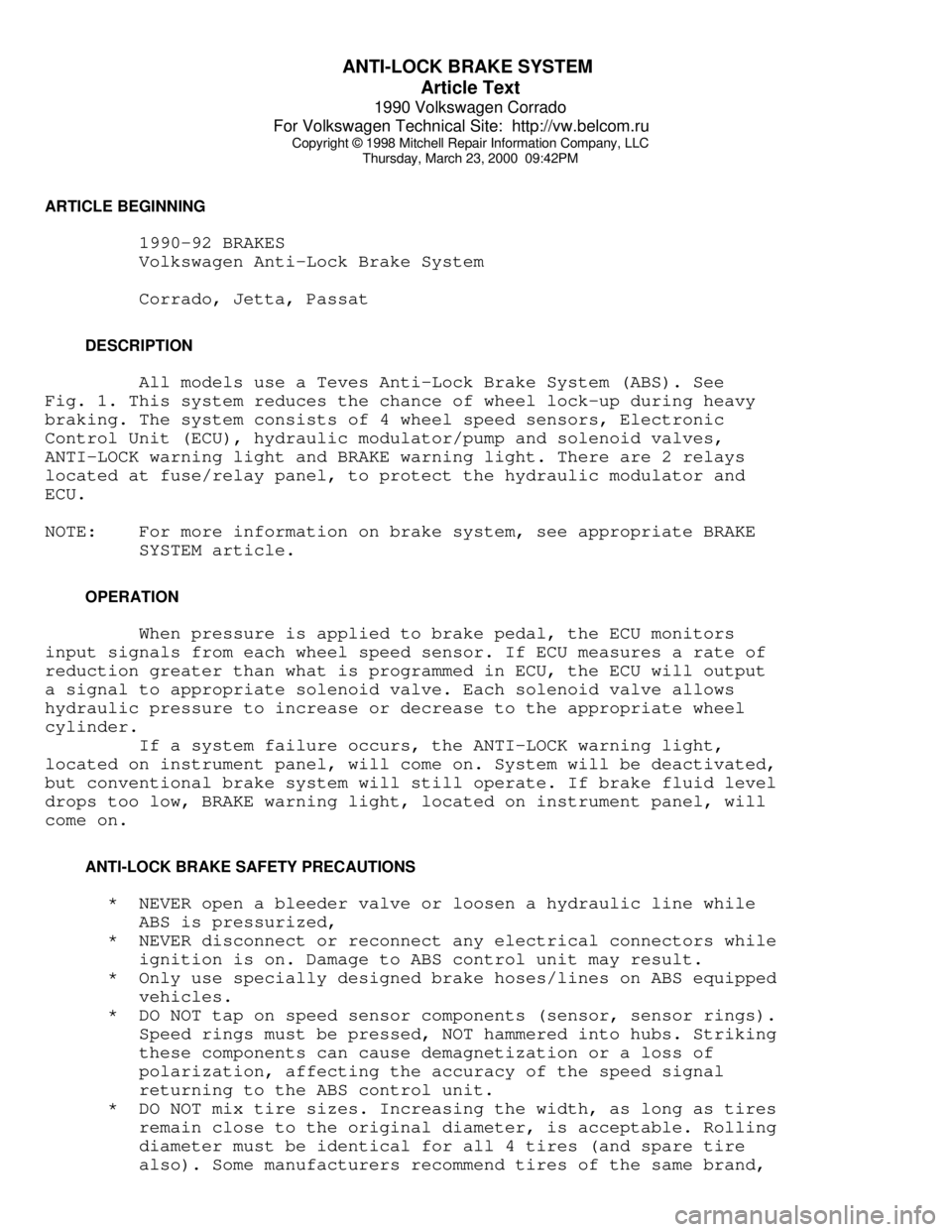
DESCRIPTION
All models use a Teves Anti-Lock Brake System (ABS). See
Fig. 1. This system reduces the chance of wheel lock-up during heavy
braking. The system consists of 4 wheel speed sensors, Electronic
Control Unit (ECU), hydraulic modulator/pump and solenoid valves,
ANTI-LOCK warning light and BRAKE warning light. There are 2 relays
located at fuse/relay panel, to protect the hydraulic modulator and
ECU.
NOTE: For more information on brake system, see appropriate BRAKE
SYSTEM article.
OPERATION
When pressure is applied to brake pedal, the ECU monitors
input signals from each wheel speed sensor. If ECU measures a rate of
reduction greater than what is programmed in ECU, the ECU will output
a signal to appropriate solenoid valve. Each solenoid valve allows
hydraulic pressure to increase or decrease to the appropriate wheel
cylinder.
If a system failure occurs, the ANTI-LOCK warning light,
located on instrument panel, will come on. System will be deactivated,
but conventional brake system will still operate. If brake fluid level
drops too low, BRAKE warning light, located on instrument panel, will
come on.
ANTI-LOCK BRAKE SAFETY PRECAUTIONS
* NEVER open a bleeder valve or loosen a hydraulic line while
ABS is pressurized,
* NEVER disconnect or reconnect any electrical connectors while
ignition is on. Damage to ABS control unit may result.
* Only use specially designed brake hoses/lines on ABS equipped
vehicles.
* DO NOT tap on speed sensor components (sensor, sensor rings).
Speed rings must be pressed, NOT hammered into hubs. Striking
these components can cause demagnetization or a loss of
polarization, affecting the accuracy of the speed signal
returning to the ABS control unit.
* DO NOT mix tire sizes. Increasing the width, as long as tires
remain close to the original diameter, is acceptable. Rolling
diameter must be identical for all 4 tires (and spare tire
also). Some manufacturers recommend tires of the same brand,
Page 410 of 906

ANTI-LOCK BRAKE SYSTEM
Article Text (p. 2)
1990 Volkswagen Corrado
For Volkswagen Technical Site: http://vw.belcom.ru
Copyright © 1998 Mitchell Repair Information Company, LLC
Thursday, March 23, 2000 09:42PM
style and type. Failure to follow this precaution may cause
inaccurate wheel speed readings.
* DO NOT contaminate speed sensor components with grease. Only
use recommended anti-corrosion coating.
* When speed sensor components have been removed, ALWAYS check
sensor-to-ring gap when applicable. These specifications can
be found in WHEEL SPEED SENSOR under ADJUSTMENTS.
* ONLY use recommended brake fluids. DO NOT use silicone brake
fluids in an ABS equipped vehicle.
* When installing transmitting devices (CB's, telephones, ect.)
on ABS equipped vehicles, DO NOT locate antenna near the ABS
control unit or any control unit.
* Disconnect all on-board computers when using electric welding
equipment.
* DO NOT expose the ABS control unit to prolonged periods of
high heat (185øF/85øC for 2 hours is generally considered a
maximum limit).
CAUTION: The ABS system is under extremely high pressure.
Depressurize the brake system before loosening or removing
any hydraulic component.
DEPRESSURIZING BRAKE SYSTEM
Turn ignition off. Depress and release brake pedal 25-35
times, or until there is a noticeable increase in the effort to
depress the brake pedal. Do not turn ignition on until all hydraulic
lines and components are fully tighten.
BLEEDING BRAKE SYSTEM
FRONT BRAKES
Depressurize brake system. See DEPRESSURIZING BRAKE SYSTEM.
Connect a container with hose to left front bleeder screw. Have
assistant depress and release brake pedal a few times. Holding brake
pedal down, open bleeder screw and allow fluid to enter container.
Close bleeder screw and then release brake pedal. Continue this method
until no air is present in fluid. Check master cylinder fluid level to
make sure it does not go below minimum level mark. Use same procedure
for right front brake.
REAR BRAKES
CAUTION: When bleeding rear brakes, accumulator pressure (about 3100
psi) is used to assist in procedure. Use eye protection
when performing this procedure. DO NOT allow pump to run
longer than 2 minutes. See ANTI-LOCK BRAKE SAFETY
PRECAUTIONS in this article.
Attach hose and container to right rear bleeder screw.
Position actuator lever on load-sensing pressure regulator toward rear
Page 413 of 906
ANTI-LOCK BRAKE SYSTEM
Article Text (p. 5)
1990 Volkswagen Corrado
For Volkswagen Technical Site: http://vw.belcom.ru
Copyright © 1998 Mitchell Repair Information Company, LLC
Thursday, March 23, 2000 09:42PM
Turn ignition on. Apply brakes. Check for 12 volts between
terminals No. 12 and 1. If 12 volts are present, brakelight switch is
okay. If 12 volts are not present, check fuse, brakelight switch and
Black/Red wire from brakelight switch to ECU.
Hydraulic Modulator/Pump Relay Voltage Test
1) Turn ignition off. Unplug hydraulic modulator/pump
connector. Depress brake pedal 25 times. Turn ignition on. Using a
voltmeter, measure voltage between ECU connector terminals No. 1 and
32. See Fig. 2. If voltage is 10 volts or more, go to RIGHT REAR WHEEL
SPEED SENSOR VOLTAGE TEST under SYSTEM TESTING.
2) If voltage is less than 10 volts, check hydraulic
modulator/pump fuse. If fuse is okay, check wiring between ECU
connector terminal No. 32 and hydraulic modulator/pump connector
terminal No. 1 (large gauge Red/Black wire). See Figs. 2 and 4-9. If
wiring is not okay, repair wiring, and retest. If wiring is okay,
replace relay, and retest.
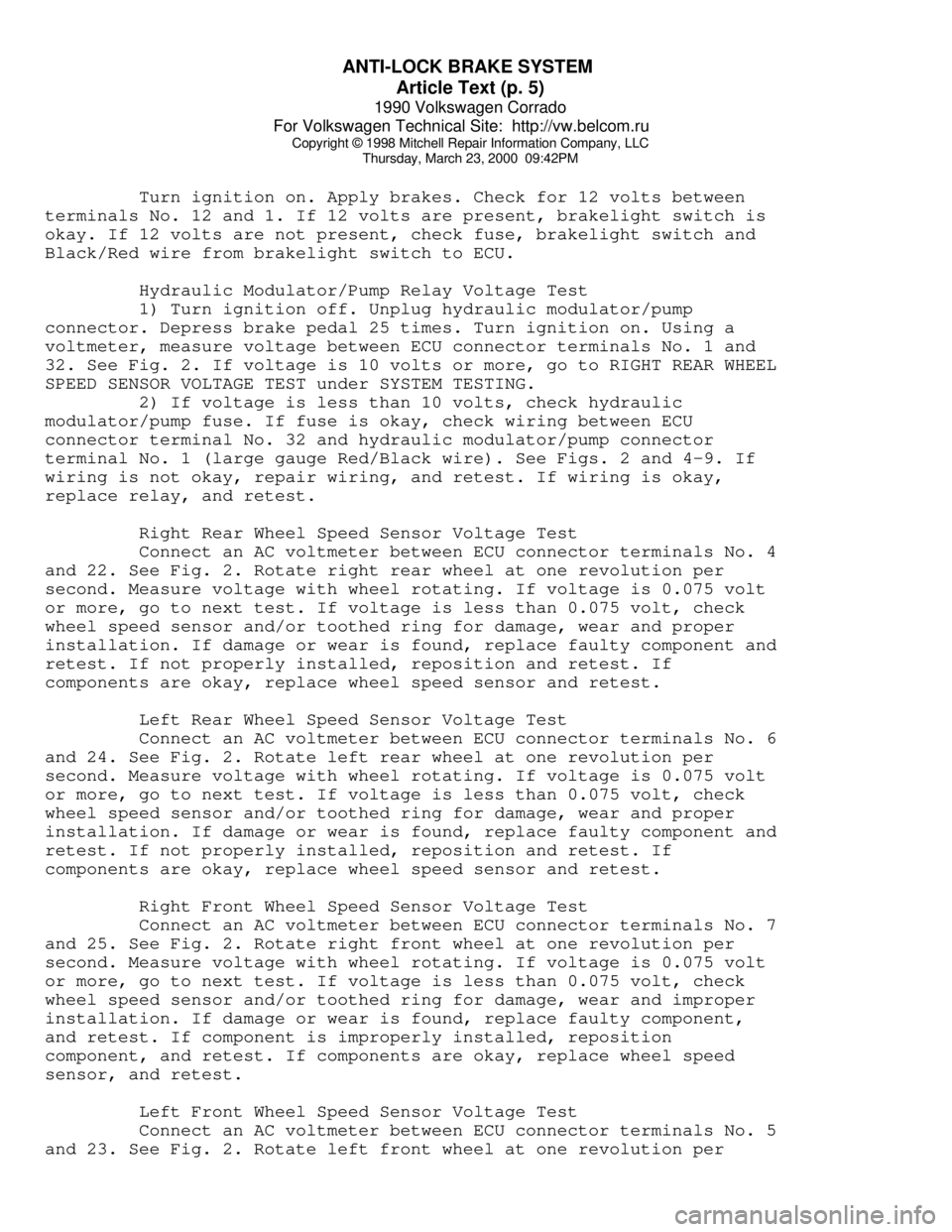
Right Rear Wheel Speed Sensor Voltage Test
Connect an AC voltmeter between ECU connector terminals No. 4
and 22. See Fig. 2. Rotate right rear wheel at one revolution per
second. Measure voltage with wheel rotating. If voltage is 0.075 volt
or more, go to next test. If voltage is less than 0.075 volt, check
wheel speed sensor and/or toothed ring for damage, wear and proper
installation. If damage or wear is found, replace faulty component and
retest. If not properly installed, reposition and retest. If
components are okay, replace wheel speed sensor and retest.
Left Rear Wheel Speed Sensor Voltage Test
Connect an AC voltmeter between ECU connector terminals No. 6
and 24. See Fig. 2. Rotate left rear wheel at one revolution per
second. Measure voltage with wheel rotating. If voltage is 0.075 volt
or more, go to next test. If voltage is less than 0.075 volt, check
wheel speed sensor and/or toothed ring for damage, wear and proper
installation. If damage or wear is found, replace faulty component and
retest. If not properly installed, reposition and retest. If
components are okay, replace wheel speed sensor and retest.
Right Front Wheel Speed Sensor Voltage Test
Connect an AC voltmeter between ECU connector terminals No. 7
and 25. See Fig. 2. Rotate right front wheel at one revolution per
second. Measure voltage with wheel rotating. If voltage is 0.075 volt
or more, go to next test. If voltage is less than 0.075 volt, check
wheel speed sensor and/or toothed ring for damage, wear and improper
installation. If damage or wear is found, replace faulty component,
and retest. If component is improperly installed, reposition
component, and retest. If components are okay, replace wheel speed
sensor, and retest.
Left Front Wheel Speed Sensor Voltage Test
Connect an AC voltmeter between ECU connector terminals No. 5
and 23. See Fig. 2. Rotate left front wheel at one revolution per