brakes VOLKSWAGEN CORRADO 1990 Owner's Manual
[x] Cancel search | Manufacturer: VOLKSWAGEN, Model Year: 1990, Model line: CORRADO, Model: VOLKSWAGEN CORRADO 1990Pages: 906, PDF Size: 6.56 MB
Page 286 of 906

* SYMPTOM CHECK LIST *
Article Text (p. 9)
1990 Volkswagen Corrado
For Volkswagen Technical Site: http://vw.belcom.ru
Copyright © 1998 Mitchell Repair Information Company, LLC
Thursday, March 23, 2000 09:40PMFig. 7: Brakes, Steering, & Suspension
Page 407 of 906

ANTI-LOCK BRAKE SAFETY PRECAUTIONS
Article Text
1990 Volkswagen Corrado
For Volkswagen Technical Site: http://vw.belcom.ru
Copyright © 1998 Mitchell Repair Information Company, LLC
Thursday, March 23, 2000 09:42PM
ARTICLE BEGINNING
GENERAL INFORMATION
Anti-Lock Brake Safety Precautions
* PLEASE READ THIS FIRST *
This article is intended for general information purposes
only. This information may not apply to all makes and models. If
vehicle is equipped with Anti-Lock Brake System (ABS), refer to
appropriate ANTI-LOCK BRAKE SYSTEM article in the BRAKES section for
description, operation, depressurizing, testing, system bleeding,
trouble shooting and servicing of specific system.
WARNING: Failure to depressurize ABS could lead to physical injury.
ANTI-LOCK BRAKE SAFETY PRECAUTIONS
WARNING: Failure to depressurize ABS could lead to physical injury.
* NEVER open a bleeder valve or loosen a hydraulic line
while ABS is pressurized.
* NEVER disconnect or reconnect any electrical connectors
while ignition is on. Damage to ABS control unit may result.
* DO NOT attempt to bleed hyudarulic system without first
referring to the appropriate ANTI-LOCK BRAKE SYSTEM article
in the BRAKES section.
* Only use specially designed brake hoses/lines on ABS equipped
vehicles.
* DO NOT tap on speed sensor components (sensor, sensor rings).
Sensor rings must be pressed into hubs, NOT hammered into
hubs. Striking these components can cause demagnetization or
a loss of polarization, affecting the accuracy of the speed
signal returning to the ABS control unit.
* DO NOT mix tire sizes. Increasing the width, as long as tires
remain close to the original diameter, is acceptable. Rolling
diameter must be identical for all 4 tires. Some
manufacturers recommend tires of the same brand, style and
type. Failure to follow this precaution may cause inaccurate
wheel speed readings.
* DO NOT contaminate speed sensor components with grease. Only
use recommended coating, when system calls for an
anti-corrosion coating.
* When speed sensor components have been removed, ALWAYS check
sensor-to-ring air gaps when applicable. These specifications
can be found in each appropriate article.
* ONLY use rocommended brake fluids. DO NOT use silicone brake
fluids in an ABS equipped vehicle.
* When instlling transmittion devices (CB's, telephones, etc.)
on ABS equipped vehicles, DO NOT locate the antenna near the
ABS control unit (or any control unit).
Page 409 of 906
ANTI-LOCK BRAKE SYSTEM
Article Text
1990 Volkswagen Corrado
For Volkswagen Technical Site: http://vw.belcom.ru
Copyright © 1998 Mitchell Repair Information Company, LLC
Thursday, March 23, 2000 09:42PM
ARTICLE BEGINNING
1990-92 BRAKES
Volkswagen Anti-Lock Brake System
Corrado, Jetta, Passat
DESCRIPTION
All models use a Teves Anti-Lock Brake System (ABS). See
Fig. 1. This system reduces the chance of wheel lock-up during heavy
braking. The system consists of 4 wheel speed sensors, Electronic
Control Unit (ECU), hydraulic modulator/pump and solenoid valves,
ANTI-LOCK warning light and BRAKE warning light. There are 2 relays
located at fuse/relay panel, to protect the hydraulic modulator and
ECU.
NOTE: For more information on brake system, see appropriate BRAKE
SYSTEM article.
OPERATION
When pressure is applied to brake pedal, the ECU monitors
input signals from each wheel speed sensor. If ECU measures a rate of
reduction greater than what is programmed in ECU, the ECU will output
a signal to appropriate solenoid valve. Each solenoid valve allows
hydraulic pressure to increase or decrease to the appropriate wheel
cylinder.
If a system failure occurs, the ANTI-LOCK warning light,
located on instrument panel, will come on. System will be deactivated,
but conventional brake system will still operate. If brake fluid level
drops too low, BRAKE warning light, located on instrument panel, will
come on.
ANTI-LOCK BRAKE SAFETY PRECAUTIONS
* NEVER open a bleeder valve or loosen a hydraulic line while
ABS is pressurized,
* NEVER disconnect or reconnect any electrical connectors while
ignition is on. Damage to ABS control unit may result.
* Only use specially designed brake hoses/lines on ABS equipped
vehicles.
* DO NOT tap on speed sensor components (sensor, sensor rings).
Speed rings must be pressed, NOT hammered into hubs. Striking
these components can cause demagnetization or a loss of
polarization, affecting the accuracy of the speed signal
returning to the ABS control unit.
* DO NOT mix tire sizes. Increasing the width, as long as tires
remain close to the original diameter, is acceptable. Rolling
diameter must be identical for all 4 tires (and spare tire
also). Some manufacturers recommend tires of the same brand,
Page 410 of 906

ANTI-LOCK BRAKE SYSTEM
Article Text (p. 2)
1990 Volkswagen Corrado
For Volkswagen Technical Site: http://vw.belcom.ru
Copyright © 1998 Mitchell Repair Information Company, LLC
Thursday, March 23, 2000 09:42PM
style and type. Failure to follow this precaution may cause
inaccurate wheel speed readings.
* DO NOT contaminate speed sensor components with grease. Only
use recommended anti-corrosion coating.
* When speed sensor components have been removed, ALWAYS check
sensor-to-ring gap when applicable. These specifications can
be found in WHEEL SPEED SENSOR under ADJUSTMENTS.
* ONLY use recommended brake fluids. DO NOT use silicone brake
fluids in an ABS equipped vehicle.
* When installing transmitting devices (CB's, telephones, ect.)
on ABS equipped vehicles, DO NOT locate antenna near the ABS
control unit or any control unit.
* Disconnect all on-board computers when using electric welding
equipment.
* DO NOT expose the ABS control unit to prolonged periods of
high heat (185øF/85øC for 2 hours is generally considered a
maximum limit).
CAUTION: The ABS system is under extremely high pressure.
Depressurize the brake system before loosening or removing
any hydraulic component.
DEPRESSURIZING BRAKE SYSTEM
Turn ignition off. Depress and release brake pedal 25-35
times, or until there is a noticeable increase in the effort to
depress the brake pedal. Do not turn ignition on until all hydraulic
lines and components are fully tighten.
BLEEDING BRAKE SYSTEM
FRONT BRAKES
Depressurize brake system. See DEPRESSURIZING BRAKE SYSTEM.
Connect a container with hose to left front bleeder screw. Have
assistant depress and release brake pedal a few times. Holding brake
pedal down, open bleeder screw and allow fluid to enter container.
Close bleeder screw and then release brake pedal. Continue this method
until no air is present in fluid. Check master cylinder fluid level to
make sure it does not go below minimum level mark. Use same procedure
for right front brake.
REAR BRAKES
CAUTION: When bleeding rear brakes, accumulator pressure (about 3100
psi) is used to assist in procedure. Use eye protection
when performing this procedure. DO NOT allow pump to run
longer than 2 minutes. See ANTI-LOCK BRAKE SAFETY
PRECAUTIONS in this article.
Attach hose and container to right rear bleeder screw.
Position actuator lever on load-sensing pressure regulator toward rear
Page 413 of 906
ANTI-LOCK BRAKE SYSTEM
Article Text (p. 5)
1990 Volkswagen Corrado
For Volkswagen Technical Site: http://vw.belcom.ru
Copyright © 1998 Mitchell Repair Information Company, LLC
Thursday, March 23, 2000 09:42PM
Turn ignition on. Apply brakes. Check for 12 volts between
terminals No. 12 and 1. If 12 volts are present, brakelight switch is
okay. If 12 volts are not present, check fuse, brakelight switch and
Black/Red wire from brakelight switch to ECU.
Hydraulic Modulator/Pump Relay Voltage Test
1) Turn ignition off. Unplug hydraulic modulator/pump
connector. Depress brake pedal 25 times. Turn ignition on. Using a
voltmeter, measure voltage between ECU connector terminals No. 1 and
32. See Fig. 2. If voltage is 10 volts or more, go to RIGHT REAR WHEEL
SPEED SENSOR VOLTAGE TEST under SYSTEM TESTING.
2) If voltage is less than 10 volts, check hydraulic
modulator/pump fuse. If fuse is okay, check wiring between ECU
connector terminal No. 32 and hydraulic modulator/pump connector
terminal No. 1 (large gauge Red/Black wire). See Figs. 2 and 4-9. If
wiring is not okay, repair wiring, and retest. If wiring is okay,
replace relay, and retest.
Right Rear Wheel Speed Sensor Voltage Test
Connect an AC voltmeter between ECU connector terminals No. 4
and 22. See Fig. 2. Rotate right rear wheel at one revolution per
second. Measure voltage with wheel rotating. If voltage is 0.075 volt
or more, go to next test. If voltage is less than 0.075 volt, check
wheel speed sensor and/or toothed ring for damage, wear and proper
installation. If damage or wear is found, replace faulty component and
retest. If not properly installed, reposition and retest. If
components are okay, replace wheel speed sensor and retest.
Left Rear Wheel Speed Sensor Voltage Test
Connect an AC voltmeter between ECU connector terminals No. 6
and 24. See Fig. 2. Rotate left rear wheel at one revolution per
second. Measure voltage with wheel rotating. If voltage is 0.075 volt
or more, go to next test. If voltage is less than 0.075 volt, check
wheel speed sensor and/or toothed ring for damage, wear and proper
installation. If damage or wear is found, replace faulty component and
retest. If not properly installed, reposition and retest. If
components are okay, replace wheel speed sensor and retest.
Right Front Wheel Speed Sensor Voltage Test
Connect an AC voltmeter between ECU connector terminals No. 7
and 25. See Fig. 2. Rotate right front wheel at one revolution per
second. Measure voltage with wheel rotating. If voltage is 0.075 volt
or more, go to next test. If voltage is less than 0.075 volt, check
wheel speed sensor and/or toothed ring for damage, wear and improper
installation. If damage or wear is found, replace faulty component,
and retest. If component is improperly installed, reposition
component, and retest. If components are okay, replace wheel speed
sensor, and retest.
Left Front Wheel Speed Sensor Voltage Test
Connect an AC voltmeter between ECU connector terminals No. 5
and 23. See Fig. 2. Rotate left front wheel at one revolution per
Page 437 of 906
COMPUTER RELEARN PROCEDURES
Article Text (p. 2)
1990 Volkswagen Corrado
For Volkswagen Technical Site: http://vw.belcom.ru
Copyright © 1998 Mitchell Repair Information Company, LLC
Thursday, March 23, 2000 09:43PM
"D" and allow engine to idle for one minute.
* Accelerate at normal throttle position (20-50%) until vehicle
shifts into top gear.
* Cruise at light to medium throttle.
* Decelerate to a stop, allowing vehicle to downshift, and use
brakes normally.
* Process may be repeated as necessary.
Manual Transmission
* Place transmission in Neutral position.
* Ensure emergency brake has been set and all accessories
are turned off.
* Start engine and bring to normal operating temperature.
* Allow vehicle to idle in Neutral for one minute.
* Initial relearn is complete: process will be completed during
normal driving.
Some manufacturers identify a specific relearn procedure
which will help establish suitable driveability during relearn stage.
These procedures are especially important if vehicle is equipped with
and electronically controlled automatic transmission or transaxle.
Always complete procedure before returning vehicle to customer.
END OF ARTICLE
Page 685 of 906
SCHEDULED SERVICES
Article Text (p. 2)
1990 Volkswagen Corrado
For Volkswagen Technical Site: http://vw.belcom.ru
Copyright © 1998 Mitchell Repair Information Company, LLC
Thursday, March 23, 2000 09:49PM
SUPPLEMENTAL RESTRAINT SYSTEM (SRS) AIR BAR WARNING
NOTE: For information on air bag DIAGNOSIS & TESTING or DISPOSAL
PROCEDURES, see AIR BAGS article in the ACCESSORIES/SAFETY
EQUIPMENT Section.
System circuit is grounded by 2 screws beneath the driver's
seat. DO NOT use these screws to ground any other accessory. DO NOT
ground any other components near this system.
AIR CONDITIONING SERVICING (1993 & LATER)
CAUTION: Avoid breathing R-134a refrigerant and PAG lubricant vapors,
exposure may irritate eyes, nose and throat. To remove
R-134a from system use R-134a recycling equipment that meets
SAE J2210 specifications. If accidental system discharge
occurs, ventilate work area before resuming service.
WARNING: R-134a service equipment or vehicle A/C systems SHOULD NOT
be pressure tested or leak tested with compressed air. Some
mixtures of air/R134a have shown to be combustible at
elevated pressures. These mixtures are dangerous and may
cause fire and/or explosions. See AIR CONDITIONING SERVICE
article in GENERAL INFORMATION section.
ANTI-LOCK BRAKE SYSTEM
The anti-lock brake system contains electronic equipment that
can be susceptible to interference caused by improperly installed or
high output radio transmitting equipment. Since this interference
could cause the possible loss of the anti-lock braking capability,
such equipment should be installed by qualified professionals.
On models equipped with anti-lock brake systems, ALWAYS
observe the following cautions:
* DO NOT attempt to bleed hydraulic system without first
referring to the appropriate ANTI-LOCK BRAKE SYSTEM article
in the BRAKES Section.
* DO NOT mix tire sizes. As long as tires remain close to the
original diameter, increasing the width is acceptable.
Rolling diameter must be identical for all 4 tires. Some
manufacturers recommend tires of the same brand, style and
type. Failure to follow this precaution may cause inaccurate
wheel speed readings.
* Use ONLY recommended brake fluids. DO NOT use silicone brake
fluids in an ABS-equipped vehicle.
BATTERY WARNING
WARNING: When battery is disconnected, vehicles equipped with
computers may lose memory data. When battery power is
Page 762 of 906
SUSPENSION - REAR
Article Text (p. 4)
1990 Volkswagen Corrado
For Volkswagen Technical Site: http://vw.belcom.ru
Copyright © 1998 Mitchell Repair Information Company, LLC
Thursday, March 23, 2000 09:51PM
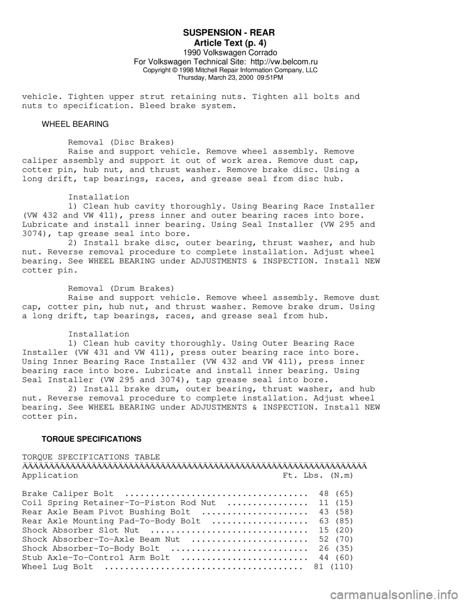
vehicle. Tighten upper strut retaining nuts. Tighten all bolts and
nuts to specification. Bleed brake system.
WHEEL BEARING
Removal (Disc Brakes)
Raise and support vehicle. Remove wheel assembly. Remove
caliper assembly and support it out of work area. Remove dust cap,
cotter pin, hub nut, and thrust washer. Remove brake disc. Using a
long drift, tap bearings, races, and grease seal from disc hub.
Installation
1) Clean hub cavity thoroughly. Using Bearing Race Installer
(VW 432 and VW 411), press inner and outer bearing races into bore.
Lubricate and install inner bearing. Using Seal Installer (VW 295 and
3074), tap grease seal into bore.
2) Install brake disc, outer bearing, thrust washer, and hub
nut. Reverse removal procedure to complete installation. Adjust wheel
bearing. See WHEEL BEARING under ADJUSTMENTS & INSPECTION. Install NEW
cotter pin.
Removal (Drum Brakes)
Raise and support vehicle. Remove wheel assembly. Remove dust
cap, cotter pin, hub nut, and thrust washer. Remove brake drum. Using
a long drift, tap bearings, races, and grease seal from hub.
Installation
1) Clean hub cavity thoroughly. Using Outer Bearing Race
Installer (VW 431 and VW 411), press outer bearing race into bore.
Using Inner Bearing Race Installer (VW 432 and VW 411), press inner
bearing race into bore. Lubricate and install inner bearing. Using
Seal Installer (VW 295 and 3074), tap grease seal into bore.
2) Install brake drum, outer bearing, thrust washer, and hub
nut. Reverse removal procedure to complete installation. Adjust wheel
bearing. See WHEEL BEARING under ADJUSTMENTS & INSPECTION. Install NEW
cotter pin.
TORQUE SPECIFICATIONS
TORQUE SPECIFICATIONS TABLEÄÄÄÄÄÄÄÄÄÄÄÄÄÄÄÄÄÄÄÄÄÄÄÄÄÄÄÄÄÄÄÄÄÄÄÄÄÄÄÄÄÄÄÄÄÄÄÄÄÄÄÄÄÄÄÄÄÄÄÄÄÄÄÄÄApplication Ft. Lbs. (N.m)
Brake Caliper Bolt .................................... 48 (65)
Coil Spring Retainer-To-Piston Rod Nut ................ 11 (15)
Rear Axle Beam Pivot Bushing Bolt ..................... 43 (58)
Rear Axle Mounting Pad-To-Body Bolt ................... 63 (85)
Shock Absorber Slot Nut ............................... 15 (20)
Shock Absorber-To-Axle Beam Nut ....................... 52 (70)
Shock Absorber-To-Body Bolt ........................... 26 (35)
Stub Axle-To-Control Arm Bolt ......................... 44 (60)
Wheel Lug Bolt ....................................... 81 (110)
Page 778 of 906

TROUBLE SHOOTING - BASIC PROCEDURES
Article Text (p. 2)
1990 Volkswagen Corrado
For Volkswagen Technical Site: http://vw.belcom.ru
Copyright © 1998 Mitchell Repair Information Company, LLC
Thursday, March 23, 2000 09:52PM
BRAKE SYSTEM TROUBLE SHOOTING
WARNING: This is GENERAL information. This article is not intended
to be specific to any unique situation or individual vehicle
configuration. The purpose of this Trouble Shooting
information is to provide a list of common causes to
problem symptoms. For model-specific Trouble Shooting,
refer to SUBJECT, DIAGNOSTIC, or TESTING articles available
in the section(s) you are accessing.
BRAKE SYSTEM TROUBLE SHOOTING CHARTÄÄÄÄÄÄÄÄÄÄÄÄÄÄÄÄÄÄÄÄÄÄÄÄÄÄÄÄÄÄÄÄÄÄÄÄÄÄÄÄÄÄÄÄÄÄÄÄÄÄÄÄÄÄÄÄÄÄÄÄÄÄÄÄÄÄÄÄÄÄCONDITION POSSIBLE CAUSE CORRECTION
ÄÄÄÄÄÄÄÄÄÄÄÄÄÄÄÄÄÄÄÄÄÄÄÄÄÄÄÄÄÄÄÄÄÄÄÄÄÄÄÄÄÄÄÄÄÄÄÄÄÄÄÄÄÄÄÄÄÄÄÄÄÄÄÄÄÄÄÄÄÄBrakes Pull Left
or Right Incorrect tire pressure Inflate tires to proper
pressure
Front end out of alignment See WHEEL ALIGNMENT
Mismatched tires Check tires sizes
Restricted brake lines
or hoses Check hose routing
Loose or malfunctioning
caliper See DISC BRAKES or
BRAKE SYSTEM
Bent shoe or oily linings See DRUM BRAKES or
BRAKE SYSTEM
Malfunctioning rear brakes See DRUM, DISC BRAKES
or BRAKE SYSTEM
Loose suspension parts See SUSPENSION
ÄÄÄÄÄÄÄÄÄÄÄÄÄÄÄÄÄÄÄÄÄÄÄÄÄÄÄÄÄÄÄÄÄÄÄÄÄÄÄÄÄÄÄÄÄÄÄÄÄÄÄÄÄÄÄÄÄÄÄÄÄÄÄÄÄÄÄÄÄÄNoises Without
Brakes Applied Front linings worn out Replace linings
Dust or oil on drums See DRUM, DISC BRAKES
or rotors or BRAKE SYSTEM
ÄÄÄÄÄÄÄÄÄÄÄÄÄÄÄÄÄÄÄÄÄÄÄÄÄÄÄÄÄÄÄÄÄÄÄÄÄÄÄÄÄÄÄÄÄÄÄÄÄÄÄÄÄÄÄÄÄÄÄÄÄÄÄÄÄÄÄÄÄÄNoises With
Brakes Applied Insulator on outboard See DISC BRAKES or
shoe damaged BRAKE SYSTEM
Incorrect pads or linings Replace pads or linings
ÄÄÄÄÄÄÄÄÄÄÄÄÄÄÄÄÄÄÄÄÄÄÄÄÄÄÄÄÄÄÄÄÄÄÄÄÄÄÄÄÄÄÄÄÄÄÄÄÄÄÄÄÄÄÄÄÄÄÄÄÄÄÄÄÄÄÄÄÄÄBrake Rough, Chatters
or Pulsates Excessive lateral runout Check rotor runout
Page 779 of 906
TROUBLE SHOOTING - BASIC PROCEDURES
Article Text (p. 3)
1990 Volkswagen Corrado
For Volkswagen Technical Site: http://vw.belcom.ru
Copyright © 1998 Mitchell Repair Information Company, LLC
Thursday, March 23, 2000 09:52PM
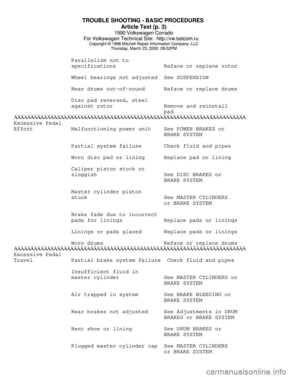
Parallelism not to
specifications Reface or replace rotor
Wheel bearings not adjusted See SUSPENSION
Rear drums out-of-round Reface or replace drums
Disc pad reversed, steel
against rotor Remove and reinstall
padÄÄÄÄÄÄÄÄÄÄÄÄÄÄÄÄÄÄÄÄÄÄÄÄÄÄÄÄÄÄÄÄÄÄÄÄÄÄÄÄÄÄÄÄÄÄÄÄÄÄÄÄÄÄÄÄÄÄÄÄÄÄÄÄÄÄÄÄÄÄExcessive Pedal
Effort Malfunctioning power unit See POWER BRAKES or
BRAKE SYSTEM
Partial system failure Check fluid and pipes
Worn disc pad or lining Replace pad or lining
Caliper piston stuck or
sluggish See DISC BRAKES or
BRAKE SYSTEM
Master cylinder piston
stuck See MASTER CYLINDERS
or BRAKE SYSTEM
Brake fade due to incorrect
pads for linings Replace pads or linings
Linings or pads glazed Replace pads or linings
Worn drums Reface or replace drums
ÄÄÄÄÄÄÄÄÄÄÄÄÄÄÄÄÄÄÄÄÄÄÄÄÄÄÄÄÄÄÄÄÄÄÄÄÄÄÄÄÄÄÄÄÄÄÄÄÄÄÄÄÄÄÄÄÄÄÄÄÄÄÄÄÄÄÄÄÄÄExcessive Pedal
Travel Partial brake system failure Check fluid and pipes
Insufficient fluid in
master cylinder See MASTER CYLINDERS or
BRAKE SYSTEM
Air trapped in system See BRAKE BLEEDING or
BRAKE SYSTEM
Rear brakes not adjusted See Adjustments in DRUM
BRAKES or BRAKE SYSTEM
Bent shoe or lining See DRUM BRAKES or
BRAKE SYSTEM
Plugged master cylinder cap See MASTER CYLINDERS
or BRAKE SYSTEM