AUX VOLKSWAGEN CORRADO 1990 Repair Manual
[x] Cancel search | Manufacturer: VOLKSWAGEN, Model Year: 1990, Model line: CORRADO, Model: VOLKSWAGEN CORRADO 1990Pages: 906, PDF Size: 6.56 MB
Page 58 of 906

* BRAKE SYSTEM UNIFORM INSPECTION GUIDELINES *
Article Text (p. 26)
1990 Volkswagen Corrado
For Volkswagen Technical Site: http://vw.belcom.ru
Copyright © 1998 Mitchell Repair Information Company, LLC
Thursday, March 23, 2000 09:29PMÄÄÄÄÄÄÄÄÄÄÄÄÄÄÄÄÄÄÄÄÄÄÄÄÄÄÄÅÄÄÄÄÄÄÅÄÄÄÄÄÄÄÄÄÄÄÄÄÄÄÄÄÄÄÄÄÄÄÄÄÄÄÄÄÄÄÄÄÄÄAlignment incorrect
³ A ³ Require repair or replacement.
ÄÄÄÄÄÄÄÄÄÄÄÄÄÄÄÄÄÄÄÄÄÄÄÄÄÄÄÅÄÄÄÄÄÄÅÄÄÄÄÄÄÄÄÄÄÄÄÄÄÄÄÄÄÄÄÄÄÄÄÄÄÄÄÄÄÄÄÄÄÄBent
³ A ³ Require replacement.
ÄÄÄÄÄÄÄÄÄÄÄÄÄÄÄÄÄÄÄÄÄÄÄÄÄÄÄÅÄÄÄÄÄÄÅÄÄÄÄÄÄÄÄÄÄÄÄÄÄÄÄÄÄÄÄÄÄÄÄÄÄÄÄÄÄÄÄÄÄÄContaminated
³ B,2 ³ Suggest cleaning; identify and
³ ³ correct cause.
ÄÄÄÄÄÄÄÄÄÄÄÄÄÄÄÄÄÄÄÄÄÄÄÄÄÄÄÅÄÄÄÄÄÄÅÄÄÄÄÄÄÄÄÄÄÄÄÄÄÄÄÄÄÄÄÄÄÄÄÄÄÄÄÄÄÄÄÄÄÄCracked
³ A ³ Require replacement.
ÄÄÄÄÄÄÄÄÄÄÄÄÄÄÄÄÄÄÄÄÄÄÄÄÄÄÄÅÄÄÄÄÄÄÅÄÄÄÄÄÄÄÄÄÄÄÄÄÄÄÄÄÄÄÄÄÄÄÄÄÄÄÄÄÄÄÄÄÄÄIncorrect number of teeth
³ A ³ Require replacement.
ÄÄÄÄÄÄÄÄÄÄÄÄÄÄÄÄÄÄÄÄÄÄÄÄÄÄÄÅÄÄÄÄÄÄÅÄÄÄÄÄÄÄÄÄÄÄÄÄÄÄÄÄÄÄÄÄÄÄÄÄÄÄÄÄÄÄÄÄÄÄLoose
³ A ³ Require replacement of worn parts.
Missing
³ A ³ Require replacement.
ÄÄÄÄÄÄÄÄÄÄÄÄÄÄÄÄÄÄÄÄÄÄÄÄÄÄÄÅÄÄÄÄÄÄÅÄÄÄÄÄÄÄÄÄÄÄÄÄÄÄÄÄÄÄÄÄÄÄÄÄÄÄÄÄÄÄÄÄÄÄTeeth broken
³ A ³ Require replacement.
ÄÄÄÄÄÄÄÄÄÄÄÄÄÄÄÄÄÄÄÄÄÄÄÄÄÄÄÅÄÄÄÄÄÄÅÄÄÄÄÄÄÄÄÄÄÄÄÄÄÄÄÄÄÄÄÄÄÄÄÄÄÄÄÄÄÄÄÄÄÄTeeth distorted
³ A ³ Further inspection required.
³ ³ See note (1) below.
ÄÄÄÄÄÄÄÄÄÄÄÄÄÄÄÄÄÄÄÄÄÄÄÄÄÄÄÅÄÄÄÄÄÄÅÄÄÄÄÄÄÄÄÄÄÄÄÄÄÄÄÄÄÄÄÄÄÄÄÄÄÄÄÄÄÄÄÄÄÄTeeth missing
³ A ³ Require replacement.
ÄÄÄÄÄÄÄÄÄÄÄÄÄÄÄÄÄÄÄÄÄÄÄÄÄÄÄÁÄÄÄÄÄÄÁÄÄÄÄÄÄÄÄÄÄÄÄÄÄÄÄÄÄÄÄÄÄÄÄÄÄÄÄÄÄÄÄÄÄÄNOTE: (1) No action required unless ABS system performance is
affected. If performance is affected, require replacement.
ÄÄÄÄÄÄÄÄÄÄÄÄÄÄÄÄÄÄÄÄÄÄÄÄÄÄÄÄÄÄÄÄÄÄÄÄÄÄÄÄÄÄÄÄÄÄÄÄÄÄÄÄÄÄÄÄÄÄÄÄÄÄÄÄÄÄÄÄÄÄ VACUUM BOOSTERS
VACUUM BOOSTERS
ÄÄÄÄÄÄÄÄÄÄÄÄÄÄÄÄÄÄÄÄÄÄÄÄÄÄÄÄÂÄÄÄÄÄÄÂÄÄÄÄÄÄÄÄÄÄÄÄÄÄÄÄÄÄÄÄÄÄÄÄÄÄÄÄÄÄÄÄÄÄCondition
³ Code ³ Procedure
ÄÄÄÄÄÄÄÄÄÄÄÄÄÄÄÄÄÄÄÄÄÄÄÄÄÄÄÄÅÄÄÄÄÄÄÅÄÄÄÄÄÄÄÄÄÄÄÄÄÄÄÄÄÄÄÄÄÄÄÄÄÄÄÄÄÄÄÄÄÄAuxiliary vacuum pump
³ A ³ Require repair or replacement.
inoperative
³ ³
ÄÄÄÄÄÄÄÄÄÄÄÄÄÄÄÄÄÄÄÄÄÄÄÄÄÄÄÄÅÄÄÄÄÄÄÅÄÄÄÄÄÄÄÄÄÄÄÄÄÄÄÄÄÄÄÄÄÄÄÄÄÄÄÄÄÄÄÄÄÄVacuum booster applies too
³ A ³ Require replacement.
much assist (oversensitive)
³ ³
ÄÄÄÄÄÄÄÄÄÄÄÄÄÄÄÄÄÄÄÄÄÄÄÄÄÄÄÄÅÄÄÄÄÄÄÅÄÄÄÄÄÄÄÄÄÄÄÄÄÄÄÄÄÄÄÄÄÄÄÄÄÄÄÄÄÄÄÄÄÄVacuum booster check valve
³ A ³ Suggest replacement of grommet.
grommet deteriorated
³ ³
ÄÄÄÄÄÄÄÄÄÄÄÄÄÄÄÄÄÄÄÄÄÄÄÄÄÄÄÄÅÄÄÄÄÄÄÅÄÄÄÄÄÄÄÄÄÄÄÄÄÄÄÄÄÄÄÄÄÄÄÄÄÄÄÄÄÄÄÄÄÄVacuum booster check valve
³ A ³ Require replacement of check
leaking
³ ³ valve.
ÄÄÄÄÄÄÄÄÄÄÄÄÄÄÄÄÄÄÄÄÄÄÄÄÄÄÄÄÅÄÄÄÄÄÄÅÄÄÄÄÄÄÄÄÄÄÄÄÄÄÄÄÄÄÄÄÄÄÄÄÄÄÄÄÄÄÄÄÄÄVacuum booster check valve
³ A ³ Require replacement of check
missing
³ ³ valve.
ÄÄÄÄÄÄÄÄÄÄÄÄÄÄÄÄÄÄÄÄÄÄÄÄÄÄÄÄÅÄÄÄÄÄÄÅÄÄÄÄÄÄÄÄÄÄÄÄÄÄÄÄÄÄÄÄÄÄÄÄÄÄÄÄÄÄÄÄÄÄ stuck closed
³ ³ valve.
ÄÄÄÄÄÄÄÄÄÄÄÄÄÄÄÄÄÄÄÄÄÄÄÄÄÄÄÄÅÄÄÄÄÄÄÅÄÄÄÄÄÄÄÄÄÄÄÄÄÄÄÄÄÄÄÄÄÄÄÄÄÄÄÄÄÄÄÄÄÄVacuum booster check valve
³ A ³ Require replacement of check
stuck open
³ ³ valve.
ÄÄÄÄÄÄÄÄÄÄÄÄÄÄÄÄÄÄÄÄÄÄÄÄÄÄÄÄÅÄÄÄÄÄÄÅÄÄÄÄÄÄÄÄÄÄÄÄÄÄÄÄÄÄÄÄÄÄÄÄÄÄÄÄÄÄÄÄÄÄ
Page 378 of 906

ABBREVIATIONS
Article Text
1990 Volkswagen Corrado
For Volkswagen Technical Site: http://vw.belcom.ru
Copyright © 1998 Mitchell Repair Information Company, LLC
Thursday, March 23, 2000 09:42PM
ARTICLE BEGINNING
GENERAL INFORMATION
COMMONLY USED ABBREVIATION
"A" ABBREVIATION TABLE
"A" ABBREVIATION TABLEÚÄÄÄÄÄÄÄÄÄÄÄÄÄÄÄÄÄÂÄÄÄÄÄÄÄÄÄÄÄÄÄÄÄÄÄÄÄÄÄÄÄÄÄÄÄÄÄÄÄÄÄÄÄÄÄÄÄÄÄÄÄÄÄÄÄÄÄÄ¿
³ABBREVIATION
³DEFINITION ³
ÃÄÄÄÄÄÄÄÄÄÄÄÄÄÄÄÄÄÅÄÄÄÄÄÄÄÄÄÄÄÄÄÄÄÄÄÄÄÄÄÄÄÄÄÄÄÄÄÄÄÄÄÄÄÄÄÄÄÄÄÄÄÄÄÄÄÄÄÄ´
³A
³Amperes ³
³A/C
³Air Conditioning ³
³A/T
³Automatic Transmission/Transaxle ³
³AAP
³Auxiliary Accelerator Pump ³
³AB
³Air Bleed ³
³ABCV
³Air Bleed Control Valve ³
³ABDC
³After Bottom Dead Center ³
³ABRS
³Air Bag Restraint System ³
³ABS
³Anti-Lock Brake System ³
³AC
³Alternating Current ³
³ACC
³A/C Clutch Compressor ³
³ACCS
³A/C Cycling Switch ³
³ACCUM
³Accumulator ³
³ACCY
³Accessory ³
³ACT
³Air Charge Temperature Sensor ³
³ACV
³Thermactor Air Control Valve ³
³ADJ
³Adjust or Adjustable ³
³ADV
³Advance ³
³AFS
³Airflow Sensor ³
³AI
³Air Injection ³
³AIR or A.I.R.
³Air Injection Reactor ³
³AIS
³Air Injection System ³
³ALCL
³Assembly Line Communications Link ³
³ALDL
³Assembly Line Diagnostic Link ³
³ARC
³Automatic Ride Control ³
³ASCS
³Air Suction Control Solenoid ³
³ASD
³Auto Shutdown ³
³ASDM
³Air Bag System Diagnostic Module ³
³ASV
³Air Suction Valve ³
³ATC
³Automatic Temperature Control ³
³ATDC
³After Top Dead Center ³
³ATF
³Automatic Transmission Fluid ³
³ATS
³Air Temperature Sensor ³
³AXOD
³Automatic Transaxle Overdrive ³
³Abs.
³Absolute ³
³Accy.
³Accessory ³
³Alt.
³Alternator or Altitude ³
³Amp.
³Ampere ³
³Assy.
³Assembly ³
Page 379 of 906

ABBREVIATIONS
Article Text (p. 2)
1990 Volkswagen Corrado
For Volkswagen Technical Site: http://vw.belcom.ru
Copyright © 1998 Mitchell Repair Information Company, LLC
Thursday, March 23, 2000 09:42PM³Auto. ³Automatic ³
³Aux.
³Auxiliary ³
³Avg.
³Average ³
ÀÄÄÄÄÄÄÄÄÄÄÄÄÄÄÄÄÄÁÄÄÄÄÄÄÄÄÄÄÄÄÄÄÄÄÄÄÄÄÄÄÄÄÄÄÄÄÄÄÄÄÄÄÄÄÄÄÄÄÄÄÄÄÄÄÄÄÄÄÙ "B" ABBREVIATION TABLE
"B" ABBREVIATION TABLE
ÚÄÄÄÄÄÄÄÄÄÄÄÄÄÄÄÄÄÂÄÄÄÄÄÄÄÄÄÄÄÄÄÄÄÄÄÄÄÄÄÄÄÄÄÄÄÄÄÄÄÄÄÄÄÄÄÄÄÄÄÄÄÄÄÄÄÄÄÄ¿
³ABBREVIATION
³DEFINITION ³
ÃÄÄÄÄÄÄÄÄÄÄÄÄÄÄÄÄÄÅÄÄÄÄÄÄÄÄÄÄÄÄÄÄÄÄÄÄÄÄÄÄÄÄÄÄÄÄÄÄÄÄÄÄÄÄÄÄÄÄÄÄÄÄÄÄÄÄÄÄ´
³B/P
³Backpressure ³
³BAC
³By-Pass Air Control ³
³BAP
³Barometric Absolute Pressure Sensor ³
³BARO
³Barometric ³
³BBDC
³Before Bottom Dead Center ³
³BCM
³Body Control Module ³
³BDC
³Bottom Dead Center ³
³BHP
³Brake Horsepower ³
³BLK
³Black ³
³BLU
³Blue ³
³BMAP
³Barometric & Manifold Absolute Pressure Sensor ³
³BOO
³Brake On-Off Switch ³
³BP
³Barometric Pressure sensor ³
³BPS
³Barometric Pressure Sensor ³
³BPT
³Backpressure Transducer ³
³BRN
³Brown ³
³BTDC
³Before Top Dead Center ³
³BTU
³British Thermal Unit ³
³BVSV
³Bimetallic Vacuum Switching Valve ³
³Baro.
³Barometric ³
³Batt.
³Battery ³
³Bbl.
³Barrel (Example: 4-Bbl.) ³
³Blst.
³Ballast ³
³Blwr.
³Blower ³
³Brkr.
³Breaker ³
ÀÄÄÄÄÄÄÄÄÄÄÄÄÄÄÄÄÄÁÄÄÄÄÄÄÄÄÄÄÄÄÄÄÄÄÄÄÄÄÄÄÄÄÄÄÄÄÄÄÄÄÄÄÄÄÄÄÄÄÄÄÄÄÄÄÄÄÄÄÙ "C" ABBREVIATION TABLE
"C" ABBREVIATION TABLE
ÚÄÄÄÄÄÄÄÄÄÄÄÄÄÄÄÄÄÂÄÄÄÄÄÄÄÄÄÄÄÄÄÄÄÄÄÄÄÄÄÄÄÄÄÄÄÄÄÄÄÄÄÄÄÄÄÄÄÄÄÄÄÄÄÄÄÄÄÄ¿
³ABBREVIATION
³DEFINITION ³
ÃÄÄÄÄÄÄÄÄÄÄÄÄÄÄÄÄÄÅÄÄÄÄÄÄÄÄÄÄÄÄÄÄÄÄÄÄÄÄÄÄÄÄÄÄÄÄÄÄÄÄÄÄÄÄÄÄÄÄÄÄÄÄÄÄÄÄÄÄ´
³ø C
³Celsius (Degrees) ³
³C(3) I
³Computer Controlled Coil Ignition ³
³C(4)
³Computer Controlled Catalytic Converter ³
³CANP
³Canister Purge solenoid ³
³CARB
³California Air Resources Board ³
³CAT
³Catalytic Converter ³
³CB
³Circuit Breaker ³
³CBD
³Closed Bowl Distributor ³
Page 390 of 906

ABBREVIATIONS
Article Text
1990 Volkswagen Corrado
For Volkswagen Technical Site: http://vw.belcom.ru
Copyright © 1998 Mitchell Repair Information Company, LLC
Thursday, March 23, 2000 09:42PM
ARTICLE BEGINNING
GENERAL INFORMATION
COMMONLY USED ABBREVIATION
"A" ABBREVIATION TABLE
"A" ABBREVIATION TABLEÚÄÄÄÄÄÄÄÄÄÄÄÄÄÄÄÄÄÂÄÄÄÄÄÄÄÄÄÄÄÄÄÄÄÄÄÄÄÄÄÄÄÄÄÄÄÄÄÄÄÄÄÄÄÄÄÄÄÄÄÄÄÄÄÄÄÄÄÄ¿
³ABBREVIATION
³DEFINITION ³
ÃÄÄÄÄÄÄÄÄÄÄÄÄÄÄÄÄÄÅÄÄÄÄÄÄÄÄÄÄÄÄÄÄÄÄÄÄÄÄÄÄÄÄÄÄÄÄÄÄÄÄÄÄÄÄÄÄÄÄÄÄÄÄÄÄÄÄÄÄ´
³A
³Amperes ³
³A/C
³Air Conditioning ³
³A/T
³Automatic Transmission/Transaxle ³
³AAP
³Auxiliary Accelerator Pump ³
³AB
³Air Bleed ³
³ABCV
³Air Bleed Control Valve ³
³ABDC
³After Bottom Dead Center ³
³ABRS
³Air Bag Restraint System ³
³ABS
³Anti-Lock Brake System ³
³AC
³Alternating Current ³
³ACC
³A/C Clutch Compressor ³
³ACCS
³A/C Cycling Switch ³
³ACCUM
³Accumulator ³
³ACCY
³Accessory ³
³ACT
³Air Charge Temperature Sensor ³
³ACV
³Thermactor Air Control Valve ³
³ADJ
³Adjust or Adjustable ³
³ADV
³Advance ³
³AFS
³Airflow Sensor ³
³AI
³Air Injection ³
³AIR or A.I.R.
³Air Injection Reactor ³
³AIS
³Air Injection System ³
³ALCL
³Assembly Line Communications Link ³
³ALDL
³Assembly Line Diagnostic Link ³
³ARC
³Automatic Ride Control ³
³ASCD
³Automatic Speed Control Device ³
³ASCS
³Air Suction Control Solenoid ³
³ASD
³Auto Shutdown ³
³ASDM
³Air Bag System Diagnostic Module ³
³ASV
³Air Suction Valve ³
³ATC
³Automatic Temperature Control ³
³ATDC
³After Top Dead Center ³
³ATF
³Automatic Transmission Fluid ³
³ATS
³Air Temperature Sensor ³
³AXOD
³Automatic Transaxle Overdrive ³
³Abs.
³Absolute ³
³Accy.
³Accessory ³
³Alt.
³Alternator or Altitude ³
³Amp.
³Ampere ³
Page 391 of 906

ABBREVIATIONS
Article Text (p. 2)
1990 Volkswagen Corrado
For Volkswagen Technical Site: http://vw.belcom.ru
Copyright © 1998 Mitchell Repair Information Company, LLC
Thursday, March 23, 2000 09:42PM³Assy. ³Assembly ³
³Auto.
³Automatic ³
³Aux.
³Auxiliary ³
³Avg.
³Average ³
ÀÄÄÄÄÄÄÄÄÄÄÄÄÄÄÄÄÄÁÄÄÄÄÄÄÄÄÄÄÄÄÄÄÄÄÄÄÄÄÄÄÄÄÄÄÄÄÄÄÄÄÄÄÄÄÄÄÄÄÄÄÄÄÄÄÄÄÄÄÙ "B" ABBREVIATION TABLE
"B" ABBREVIATION TABLE
ÚÄÄÄÄÄÄÄÄÄÄÄÄÄÄÄÄÄÂÄÄÄÄÄÄÄÄÄÄÄÄÄÄÄÄÄÄÄÄÄÄÄÄÄÄÄÄÄÄÄÄÄÄÄÄÄÄÄÄÄÄÄÄÄÄÄÄÄÄ¿
³ABBREVIATION
³DEFINITION ³
ÃÄÄÄÄÄÄÄÄÄÄÄÄÄÄÄÄÄÅÄÄÄÄÄÄÄÄÄÄÄÄÄÄÄÄÄÄÄÄÄÄÄÄÄÄÄÄÄÄÄÄÄÄÄÄÄÄÄÄÄÄÄÄÄÄÄÄÄÄ´
³B/P
³Backpressure ³
³BAC
³By-Pass Air Control ³
³BAP
³Barometric Absolute Pressure Sensor ³
³BARO
³Barometric ³
³BBDC
³Before Bottom Dead Center ³
³BCM
³Body Control Module ³
³BDC
³Bottom Dead Center ³
³BHP
³Brake Horsepower ³
³BLK
³Black ³
³BLU
³Blue ³
³BMAP
³Barometric & Manifold Absolute Pressure Sensor ³
³BOO
³Brake On-Off Switch ³
³BP
³Barometric Pressure sensor ³
³BPS
³Barometric Pressure Sensor ³
³BPT
³Backpressure Transducer ³
³BRN
³Brown ³
³BTDC
³Before Top Dead Center ³
³BTU
³British Thermal Unit ³
³BVSV
³Bimetallic Vacuum Switching Valve ³
³Baro.
³Barometric ³
³Batt.
³Battery ³
³Bbl.
³Barrel (Example: 4-Bbl.) ³
³Blst.
³Ballast ³
³Blwr.
³Blower ³
³Brkr.
³Breaker ³
ÀÄÄÄÄÄÄÄÄÄÄÄÄÄÄÄÄÄÁÄÄÄÄÄÄÄÄÄÄÄÄÄÄÄÄÄÄÄÄÄÄÄÄÄÄÄÄÄÄÄÄÄÄÄÄÄÄÄÄÄÄÄÄÄÄÄÄÄÄÙ "C" ABBREVIATION TABLE
"C" ABBREVIATION TABLE
ÚÄÄÄÄÄÄÄÄÄÄÄÄÄÄÄÄÄÂÄÄÄÄÄÄÄÄÄÄÄÄÄÄÄÄÄÄÄÄÄÄÄÄÄÄÄÄÄÄÄÄÄÄÄÄÄÄÄÄÄÄÄÄÄÄÄÄÄÄ¿
³ABBREVIATION
³DEFINITION ³
ÃÄÄÄÄÄÄÄÄÄÄÄÄÄÄÄÄÄÅÄÄÄÄÄÄÄÄÄÄÄÄÄÄÄÄÄÄÄÄÄÄÄÄÄÄÄÄÄÄÄÄÄÄÄÄÄÄÄÄÄÄÄÄÄÄÄÄÄÄ´
³ø C
³Celsius (Degrees) ³
³C(3) I
³Computer Controlled Coil Ignition ³
³C(4)
³Computer Controlled Catalytic Converter ³
³CANP
³Canister Purge solenoid ³
³CARB
³California Air Resources Board ³
³CAT
³Catalytic Converter ³
³CB
³Circuit Breaker ³
Page 440 of 906
D - ADJUSTMENTS
Article Text (p. 3)
1990 Volkswagen Corrado
For Volkswagen Technical Site: http://vw.belcom.ru
Copyright © 1998 Mitchell Repair Information Company, LLC
Thursday, March 23, 2000 09:43PM
NOTE: Mixture adjustment is NOT a part of normal tune-up procedure
and should not be performed unless mixture control unit is
replaced or vehicle fails emissions testing.
NOTE: Ensure system pressure is correct before attempting idle
speed or mixture adjustment.
IDLE SPEED & MIXTURE ADJUSTMENT
FOX (CIS-E) & JETTA GLI 2.0L (CIS-MOTRONIC)
1) Ignition timing and idle speed must be checked before CO
is adjusted. See CHECKING & ADJUSTING under IGNITION TIMING. With
ignition timing properly adjusted, check and adjust idle speed,
differential pressure regulator current and idle mixture. Repeat the
adjustments until all occur at the same time.
2) Warm engine to normal operating temperature. Radiator fan
must come on at least once and engine oil temperature must be at least
176øF (80øC). Turn off all electrical equipment, including A/C and
radiator fan. Disconnect all fuel pressure test equipment (if
installed). If injection lines have been removed or replaced, run
engine several times to 3000 RPM for about 2 minutes.
3) Ensure idle switch is properly adjusted. Check that
auxiliary air regulator valve is fully closed. Pinch shut the hose
leading from the idle speed boost valve(s). Remove temperature sensor
harness connector from the temperature sensor. Pull crankcase breather
hoses off valve cover and air filter, vent to atmosphere.
4) Remove suction hose from carbon canister. Disconnect "T"
fitting from carbon canister at air intake boot. On Fox models only,
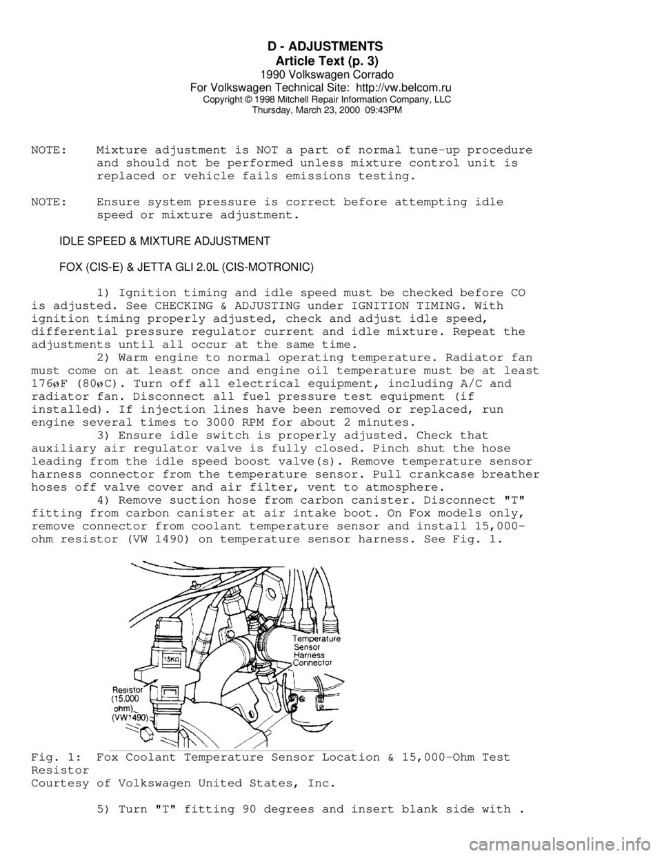
remove connector from coolant temperature sensor and install 15,000-
ohm resistor (VW 1490) on temperature sensor harness. See Fig. 1.Fig. 1: Fox Coolant Temperature Sensor Location & 15,000-Ohm Test
Resistor
Courtesy of Volkswagen United States, Inc.
5) Turn "T" fitting 90 degrees and insert blank side with .
Page 497 of 906
EMISSION CONTROL VISUAL INSPECTION PROCEDURES
Article Text (p. 3)
1990 Volkswagen Corrado
For Volkswagen Technical Site: http://vw.belcom.ru
Copyright © 1998 Mitchell Repair Information Company, LLC
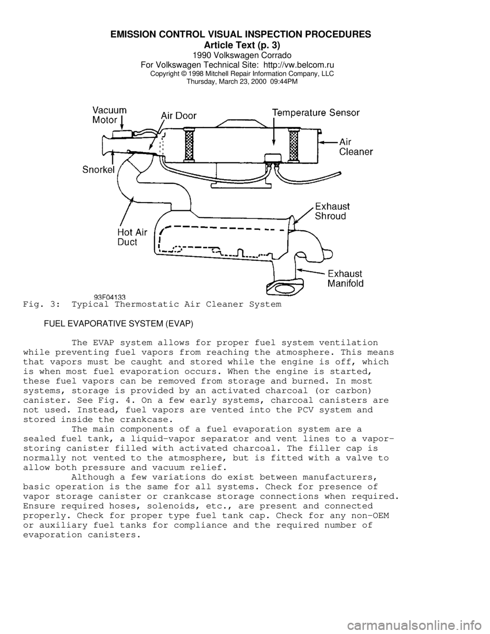
Thursday, March 23, 2000 09:44PMFig. 3: Typical Thermostatic Air Cleaner System
FUEL EVAPORATIVE SYSTEM (EVAP)
The EVAP system allows for proper fuel system ventilation
while preventing fuel vapors from reaching the atmosphere. This means
that vapors must be caught and stored while the engine is off, which
is when most fuel evaporation occurs. When the engine is started,
these fuel vapors can be removed from storage and burned. In most
systems, storage is provided by an activated charcoal (or carbon)
canister. See Fig. 4. On a few early systems, charcoal canisters are
not used. Instead, fuel vapors are vented into the PCV system and
stored inside the crankcase.
The main components of a fuel evaporation system are a
sealed fuel tank, a liquid-vapor separator and vent lines to a vapor-
storing canister filled with activated charcoal. The filler cap is
normally not vented to the atmosphere, but is fitted with a valve to
allow both pressure and vacuum relief.
Although a few variations do exist between manufacturers,
basic operation is the same for all systems. Check for presence of
vapor storage canister or crankcase storage connections when required.
Ensure required hoses, solenoids, etc., are present and connected
properly. Check for proper type fuel tank cap. Check for any non-OEM
or auxiliary fuel tanks for compliance and the required number of
evaporation canisters.
Page 499 of 906
EMISSION CONTROL VISUAL INSPECTION PROCEDURES
Article Text (p. 5)
1990 Volkswagen Corrado
For Volkswagen Technical Site: http://vw.belcom.ru
Copyright © 1998 Mitchell Repair Information Company, LLC
Thursday, March 23, 2000 09:44PM
Visually check for presence of catalytic converter(s). Also
check for presence of any required air supply system for the oxidizing
section of the converter. Check for external damage such as severe
dents, removed or damaged heat shields, etc. Check for pellets or
pieces of converter in the tailpipe.
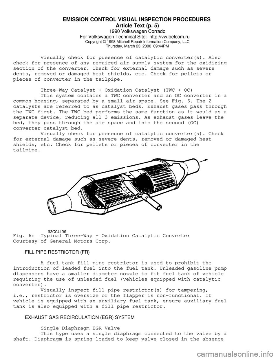
Three-Way Catalyst + Oxidation Catalyst (TWC + OC)
This system contains a TWC converter and an OC converter in a
common housing, separated by a small air space. See Fig. 6. The 2
catalysts are referred to as catalyst beds. Exhaust gases pass through
the TWC first. The TWC bed performs the same function as it would as a
separate device, reducing all 3 emissions. As exhaust gases leave the
bed, they pass through the air space and into the second (OC)
converter catalyst bed.
Visually check for presence of catalytic converter(s). Check
for external damage such as severe dents, removed or damaged heat
shields, etc. Check for pellets or pieces of converter in the
tailpipe.Fig. 6: Typical Three-Way + Oxidation Catalytic Converter
Courtesy of General Motors Corp.
FILL PIPE RESTRICTOR (FR)
A fuel tank fill pipe restrictor is used to prohibit the
introduction of leaded fuel into the fuel tank. Unleaded gasoline pump
dispensers have a smaller diameter nozzle to fit fuel tank of vehicle
requiring the use of unleaded fuel (vehicles equipped with catalytic
converter).
Visually inspect fill pipe restrictor(s) for tampering,
i.e., restrictor is oversize or the flapper is non-functional. If
vehicle is equipped with an auxiliary fuel tank, ensure auxiliary fuel
tank is also equipped with a fill pipe restrictor.
EXHAUST GAS RECIRCULATION (EGR) SYSTEM
Single Diaphragm EGR Valve
This type uses a single diaphragm connected to the valve by a
shaft. Diaphragm is spring-loaded to keep valve closed in the absence
Page 576 of 906

H - TESTS W/O CODES
Article Text (p. 3)
1990 Volkswagen Corrado
For Volkswagen Technical Site: http://vw.belcom.ru
Copyright © 1998 Mitchell Repair Information Company, LLC
Thursday, March 23, 2000 09:45PM
necessary.
* Ensure injector spray patterns and volume are correct. Replace
faulty injectors.
* Inspect fuel lines and connections for leaks.
* Check carbon canister solenoid valves (CIS-E Motronic).
* Test airflow meter. Replace if faulty.
* Ensure sufficient secondary spark is available.
* Check air induction system for cracks or restriction.
* Check airflow sensor plate rest position.
* Ensure vacuum hoses are not disconnected or damaged.
* Ensure EGR valve operation is correct and valve closes
completely (if equipped).
* Check for cracks or poor connections at throttle body.
* Ensure ignition and valve timing are correct.
* Check ignition coil primary connections and wiring harness.
* Ensure ignition coil resistance is within specification.
* Check air temperature sensor operation.
* Check coolant temperature sensor operation.
* Ensure electrical harness and connectors are not broken or loose.
* Ensure ECU or ignition control unit has correct voltage supply
and is properly grounded.
* Ensure engine has sufficient compression.
ENGINE STALLS OR IDLES ROUGH
* Check fuel system and control system pressure. Replace pressure
regulator if necessary.
* Check cold start valve for leaking (engine warm).
* Ensure injector spray patterns and volume are correct. Replace
faulty injectors.
* Test coolant temperature sensor and wiring. Repair or replace
as required.
* Inspect intake air components for leaking hoses, connections or
cracks. Repair as required.
* Ensure airflow sensor plate movement and rest position. Adjust
as necessary.
* Test idle switch and idle air stabilizer valve.
* Perform system electrical checks.
* Check airflow meter. Replace if faulty.
* Ensure idle RPM is correct.
* Check auxiliary air by-pass regulator.
* Check fuel injector electrical connections.
* Use stethoscope to verify fuel injectors are operating.
* Ensure sufficient secondary spark is available in all cylinders.
* Verify vacuum hose routing is correct and there are no
vacuum leaks.
* Check idle stabilizer operation.
* Check for EGR system malfunction (if equipped).
* Check O2 sensor operation.
* Check for distortion or cracks in fuel injector(s) plastic
connecting flange(s).
* Check for use of poor quality fuel containing insufficient
Page 577 of 906

H - TESTS W/O CODES
Article Text (p. 4)
1990 Volkswagen Corrado
For Volkswagen Technical Site: http://vw.belcom.ru
Copyright © 1998 Mitchell Repair Information Company, LLC
Thursday, March 23, 2000 09:45PM
cleaning additives. Prolonged use of poor quality fuel can
cause injector clogging and carbon build-up on intake system.
ENGINE MISFIRES OR HESITATES
CIS-E & CIS-E MOTRONIC
* Ensure injector spray patterns and volume are correct. Replace
faulty injectors.
* Check fuel system and control system pressure. Replace pressure
regulator if necessary.
* Check Oxygen (O2) sensor system operation.
* Check fuel lines and connections for leaks.
* Test coolant temperature sensor and wiring. Repair or replace
as required.
* Check airflow meter and throttle switch. Replace if faulty.
* Ensure vacuum hoses are not disconnected or damaged.
* Ensure electrical harness connectors and wires are not
broken or loose.
* Check cold start valve for leaking (engine warm).
DIGIFANT II
* Check airflow sensor flap and sensor resistance. Replace
if faulty.
* Inspect intake air components for leaking hoses, connections
or cracks. Repair as required.
* Test intake air preheating system. Replace faulty components
as required.
* Check fuel system and control system pressure. Replace pressure
regulator if necessary.
* Ensure vacuum hoses are not disconnected or damaged.
* Ensure electrical harness connectors and wires are not
broken or loose.
* Check cold start valve for leaking (engine warm).
* Check coolant temperature sensor operation.
* Check Oxygen (O2) sensor voltage output.
EXCESSIVE FAST IDLE
* Inspect accelerator pedal and cable for worn parts or binding.
* Test idle switch (if equipped).
* Test auxiliary air regulator and replace if necessary
(if equipped).
* Inspect throttle valve and adjust or replace as required.
* Check carbon canister solenoid valves (CIS-E Motronic).
* Test idle boost valve system operation (1.8L 8-valve engine
only). Replace faulty parts as necessary.
* Test coolant temperature sensor and wiring (Digifant II). Repair
or replace as required.
* Check throttle cable adjustment.
* Verify vacuum hose routing is correct.