fuel type VOLKSWAGEN CORRADO 1993 Repair Manual
[x] Cancel search | Manufacturer: VOLKSWAGEN, Model Year: 1993, Model line: CORRADO, Model: VOLKSWAGEN CORRADO 1993Pages: 920, PDF Size: 6.92 MB
Page 388 of 920
AA - USING THIS SECTION (GENERAL HELP INFORMATION)
Article Text (p. 2)
1993 Volkswagen Corrado
For Volkswagen Technical Site: http://vw.belcom.ru
Copyright © 1998 Mitchell Repair Information Company, LLC
Wednesday, March 22, 2000 08:49PM
If you want "TUNE-UP" type information, see D - ADJUSTMENTS
for the adjustment procedures. If you are familiar with the
procedures, but need a quick way to find the specification, go to C -
TUNE-UP SPECS or C - SPECIFICATIONS for the specifications pertaining
to the vehicle.
When diagnosing driveability problems, first go to F - BASIC
TESTING. This article is here to help eliminate wasted diagnostic
time. If the basic systems are working properly, go to G - TESTS W/
CODES.
If the vehicle still is having a driveability problem or if
the vehicle has no self-diagnostic system, go to H - TESTS W/O CODES.
This article will help you diagnose the problem by symptom, locate the
symptom exhibited by the vehicle, and inspect or test the items which
may be causing the problem.
After finding which specific system or component requires
testing, use the I - SYS/COMP TESTS article to tests the systems and
components. We have also included (when available) pin voltage charts
and sensor range charts. These can be found in J - PIN VOLTAGE CHARTS
and K - SENSOR RANGE CHARTS.
Also included in this section are wiring diagrams and vacuum
diagrams. These can be found in L - WIRING DIAGRAMS and M - VACUUM
DIAGRAMS.
When all diagnostic tests have been performed and the problem
has been discovered, it may be necessary to replace or overhaul the
defective part. This information can be found in
N - REMOVE/INSTALL/OHAUL.
The content of each of these articles is outlined below. As a
summary of the driveability diagnosis, see ROUTINE OUTLINE in this
article.
A - ENGINE/VIN ID
This article shows how to identify the model and engine by
its Vehicle Identification Number (VIN). A model coverage chart shows
each model and engine, the fuel system, ignition system and engine
code. The engine serial number locations are also included in this
article.
B - EMISSION APPLICATION
These charts identify the emission systems and sub-systems
applicable to each model and engine combination.
C - TUNE-UP SPECS
This is a collection of quick-reference type specifications.
This article is helpful when you are familiar with proper adjustment
procedures and only need specifications. Included in this section are:
* Battery specifications.
* Fluid capacities.
Page 389 of 920
AA - USING THIS SECTION (GENERAL HELP INFORMATION)
Article Text (p. 3)
1993 Volkswagen Corrado
For Volkswagen Technical Site: http://vw.belcom.ru
Copyright © 1998 Mitchell Repair Information Company, LLC
Wednesday, March 22, 2000 08:49PM
* Replacement intervals.
* Belt adjustment.
* Engine Compression.
* Valve clearance.
* Valve Arrangement.
* Ignition coil specifications.
* High tension wire resistance.
* Spark plug type and gap.
* Firing order.
* Ignition timing.
* Fuel pump performance and injector resistance specifications
* Slow and fast idle speed and mixture specifications.
* Carbon monoxide (CO) level specifications.
* Throttle position sensor/switch specifications.
C - SPECIFICATIONS
This is a collection of quick-reference type specifications.
This article is helpful when you are familiar with proper adjustment
procedures and only need specifications. Included in this section are:
* Battery specifications.
* Fluid capacities.
* Replacement intervals.
* Belt adjustment.
* Engine Compression.
* Valve clearance.
* Valve Arrangement.
* Ignition coil specifications.
* High tension wire resistance.
* Spark plug type and gap.
* Firing order.
* Ignition timing.
* Fuel pump performance and injector resistance specifications
* Slow and fast idle speed and mixture specifications.
* Carbon monoxide (CO) level specifications.
* Throttle position sensor/switch specifications.
D - ADJUSTMENTS
This article contains the information that use to be included
in the TUNE-UP section. Checking and adjusting valves, spark plugs,
spark plug wires, base ignition timing and idle speed are found in
this section. Use this article for routine maintenance. Also, if you
have a driveability problem, ensure all on-vehicle adjustments are
correct before proceeding with any diagnosis.
E - THEORY/OPERATION
Page 451 of 920
COMPUTER RELEARN PROCEDURES
Article Text
1993 Volkswagen Corrado
For Volkswagen Technical Site: http://vw.belcom.ru
Copyright © 1998 Mitchell Repair Information Company, LLC
Wednesday, March 22, 2000 08:58PM
ARTICLE BEGINNING
GENERAL INFORMATION
Computer Relearn Procedures
All Models
* PLEASE READ THIS FIRST *
The following general procedures are to be used if
driveability problems are encountered after power loss or battery has
been disconnected. These procedures may provide an aid in eliminating
these problems.
To reduce the possibility of complaints, after any service
which requires battery power to be disconnected, vehicle should be
road tested.
COMPUTER RELEARN PROCEDURES
Vehicles equipped with engine or transmission computers may
require a relearn procedure after vehicle battery is disconnected.
Many vehicle computers memorize and store vehicle operation patterns
for optimum driveability and performance. When vehicle battery is
disconnected, this memory is lost. The computer will use default data
until new data from each key start is stored. As computer memorizes
vehicle operation for each new key start, driveability is restored.
Vehicle computers may memorize vehicles operation patterns for 40 of
more key starts.
Customers often complain of driveability problems during
relearn stage because vehicle acts differently then before being
serviced. Depending on type and make of vehicle and how it is
equipped, the following complaints (driveability problems) may exist:
* Harsh Or Poor Shift Quality
* Rough Or Unstable Idle
* Hesitation Or Stumble
* Rich Or Lean Running
* Poor Fuel Mileage
These symptoms and complaints should disappear after a number
of drive cycles have been memorized. To reduce the possibility of
complaints, after any service which requires battery power to be
disconnected, vehicle should be road tested. If a specific relearn
procedure is not available, the following procedure may be used:
Automatic Transmission
* Set parking brake, start engine in "P" or "N" position.
Warm-up vehicle to normal operating temperature or until
cooling fan cycles.
* Allow vehicle to idle for one minute in "N" position. Select
Page 509 of 920
E - THEORY/OPERATION
Article Text (p. 4)
1993 Volkswagen Corrado
For Volkswagen Technical Site: http://vw.belcom.ru
Copyright © 1998 Mitchell Repair Information Company, LLC
Wednesday, March 22, 2000 09:09PM
Fuel Injectors
See FUEL CONTROL under FUEL SYSTEM in this article.
Fuel Pump
See FUEL DELIVERY under FUEL SYSTEM in this article.
Idle Air Control/Stabilizer Valve
See IDLE SPEED under FUEL SYSTEM in this article.
Ignition Coil & Output Stage
See DISTRIBUTORLESS IGNITION SYSTEM (DIS) under IGNITION
SYSTEM in this article.
Malfunction Indicator (CHECK ENGINE) Light
See MALFUNCTION INDICATOR (CHECK ENGINE) LIGHT under SELF-
DIAGNOSTIC SYSTEM in this article.
FUEL SYSTEM
FUEL DELIVERY
Fuel Pump
A 2-stage fuel pump, located in fuel tank, is used (one motor
drives two separate pumps). The stage one vane-type pump draws fuel,
through a screen, from bottom of fuel tank and into an accumulator.
The vane-type pump acts as a transfer pump. The stage two gear-type
pump draws fuel from bottom of accumulator and out fuel lines.
Fuel Pressure Regulator
The diaphragm-type fuel pressure regulator is attached to
fuel return side of fuel rail. Fuel pressure is regulated depending on
intake manifold pressure. As intake manifold pressure changes, the
pressure regulator will increase or decrease fuel system pressure.
FUEL CONTROL
Fuel Injectors
Fuel injectors are supplied with battery (system) voltage
through power supply relay and are controlled (grounded) by the ECM.
Injectors are opened sequentially in cylinder firing order. Fuel
quantity is determined by injector on time (duty cycle).
IDLE SPEED
Idle Air Control/Stabilizer Valve
The idle air control/stabilizer valve is actuated by the ECM
thorough the valve's ground control circuit. When a defect in circuit
is recognized, both output stages are shut-off and the valve rotates
to a fixed potion. This permits engine to idle at a warm engine idle
speed.
IGNITION SYSTEM
Page 517 of 920
EMISSION CONTROL VISUAL INSPECTION PROCEDURES
Article Text (p. 3)
1993 Volkswagen Corrado
For Volkswagen Technical Site: http://vw.belcom.ru
Copyright © 1998 Mitchell Repair Information Company, LLC
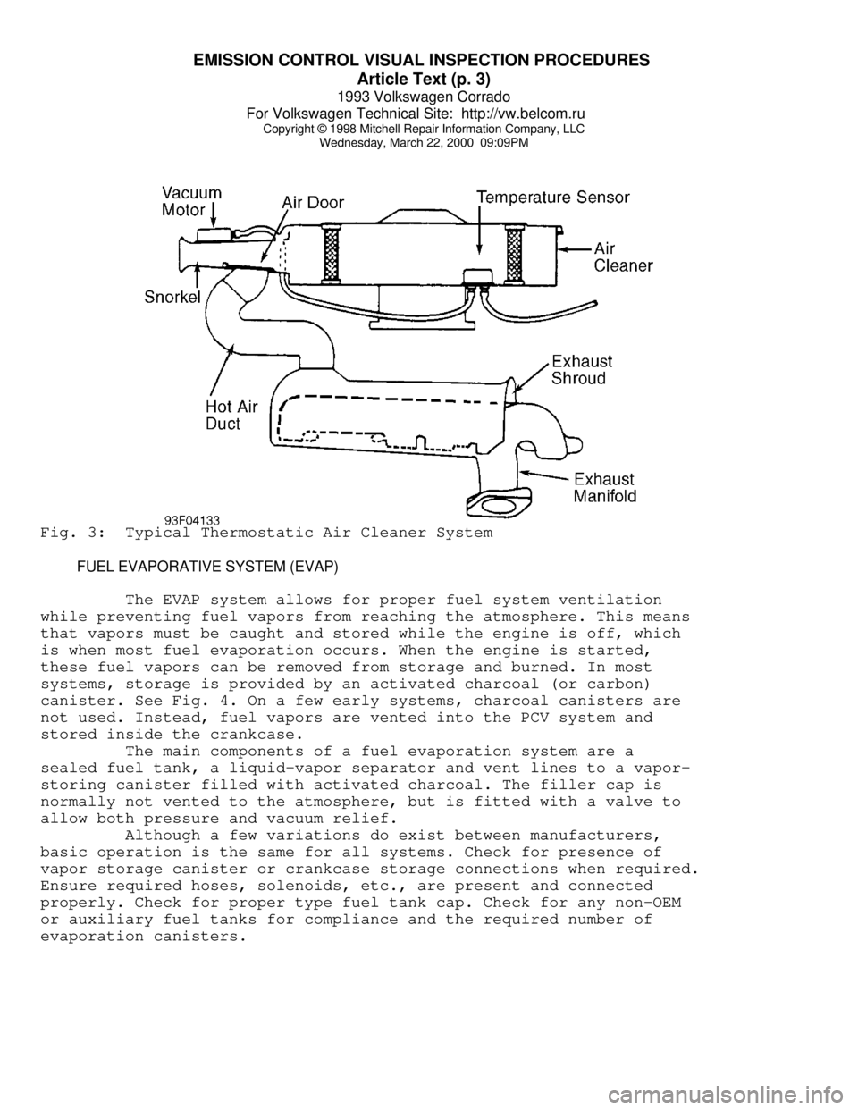
Wednesday, March 22, 2000 09:09PMFig. 3: Typical Thermostatic Air Cleaner System
FUEL EVAPORATIVE SYSTEM (EVAP)
The EVAP system allows for proper fuel system ventilation
while preventing fuel vapors from reaching the atmosphere. This means
that vapors must be caught and stored while the engine is off, which
is when most fuel evaporation occurs. When the engine is started,
these fuel vapors can be removed from storage and burned. In most
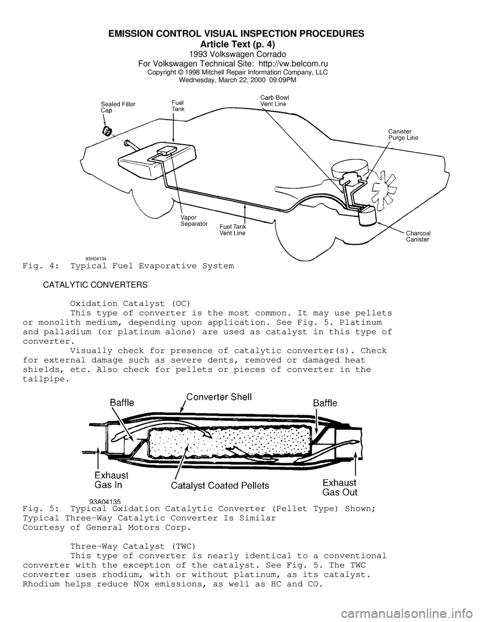
systems, storage is provided by an activated charcoal (or carbon)
canister. See Fig. 4. On a few early systems, charcoal canisters are
not used. Instead, fuel vapors are vented into the PCV system and
stored inside the crankcase.
The main components of a fuel evaporation system are a
sealed fuel tank, a liquid-vapor separator and vent lines to a vapor-
storing canister filled with activated charcoal. The filler cap is
normally not vented to the atmosphere, but is fitted with a valve to
allow both pressure and vacuum relief.
Although a few variations do exist between manufacturers,
basic operation is the same for all systems. Check for presence of
vapor storage canister or crankcase storage connections when required.
Ensure required hoses, solenoids, etc., are present and connected
properly. Check for proper type fuel tank cap. Check for any non-OEM
or auxiliary fuel tanks for compliance and the required number of
evaporation canisters.
Page 518 of 920
EMISSION CONTROL VISUAL INSPECTION PROCEDURES
Article Text (p. 4)
1993 Volkswagen Corrado
For Volkswagen Technical Site: http://vw.belcom.ru
Copyright © 1998 Mitchell Repair Information Company, LLC
Wednesday, March 22, 2000 09:09PMFig. 4: Typical Fuel Evaporative System
CATALYTIC CONVERTERS
Oxidation Catalyst (OC)
This type of converter is the most common. It may use pellets
or monolith medium, depending upon application. See Fig. 5. Platinum
and palladium (or platinum alone) are used as catalyst in this type of
converter.
Visually check for presence of catalytic converter(s). Check
for external damage such as severe dents, removed or damaged heat
shields, etc. Also check for pellets or pieces of converter in the
tailpipe.Fig. 5: Typical Oxidation Catalytic Converter (Pellet Type) Shown;
Typical Three-Way Catalytic Converter Is Similar
Courtesy of General Motors Corp.
Three-Way Catalyst (TWC)
This type of converter is nearly identical to a conventional
converter with the exception of the catalyst. See Fig. 5. The TWC
converter uses rhodium, with or without platinum, as its catalyst.
Rhodium helps reduce NOx emissions, as well as HC and CO.
Page 519 of 920
EMISSION CONTROL VISUAL INSPECTION PROCEDURES
Article Text (p. 5)
1993 Volkswagen Corrado
For Volkswagen Technical Site: http://vw.belcom.ru
Copyright © 1998 Mitchell Repair Information Company, LLC
Wednesday, March 22, 2000 09:09PM
Visually check for presence of catalytic converter(s). Also
check for presence of any required air supply system for the oxidizing
section of the converter. Check for external damage such as severe
dents, removed or damaged heat shields, etc. Check for pellets or
pieces of converter in the tailpipe.
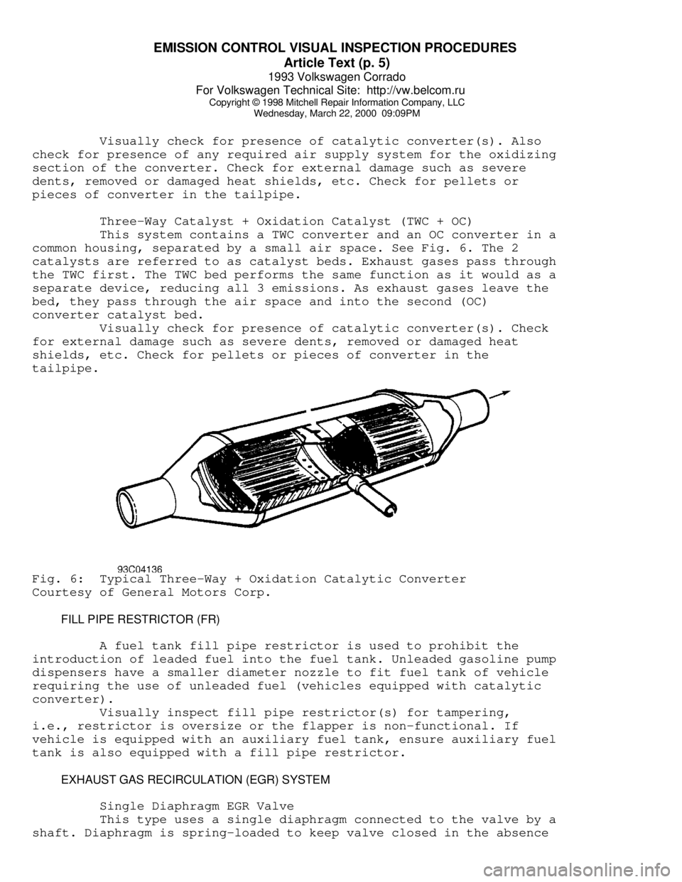
Three-Way Catalyst + Oxidation Catalyst (TWC + OC)
This system contains a TWC converter and an OC converter in a
common housing, separated by a small air space. See Fig. 6. The 2
catalysts are referred to as catalyst beds. Exhaust gases pass through
the TWC first. The TWC bed performs the same function as it would as a
separate device, reducing all 3 emissions. As exhaust gases leave the
bed, they pass through the air space and into the second (OC)
converter catalyst bed.
Visually check for presence of catalytic converter(s). Check
for external damage such as severe dents, removed or damaged heat
shields, etc. Check for pellets or pieces of converter in the
tailpipe.Fig. 6: Typical Three-Way + Oxidation Catalytic Converter
Courtesy of General Motors Corp.
FILL PIPE RESTRICTOR (FR)
A fuel tank fill pipe restrictor is used to prohibit the
introduction of leaded fuel into the fuel tank. Unleaded gasoline pump
dispensers have a smaller diameter nozzle to fit fuel tank of vehicle
requiring the use of unleaded fuel (vehicles equipped with catalytic
converter).
Visually inspect fill pipe restrictor(s) for tampering,
i.e., restrictor is oversize or the flapper is non-functional. If
vehicle is equipped with an auxiliary fuel tank, ensure auxiliary fuel
tank is also equipped with a fill pipe restrictor.
EXHAUST GAS RECIRCULATION (EGR) SYSTEM
Single Diaphragm EGR Valve
This type uses a single diaphragm connected to the valve by a
shaft. Diaphragm is spring-loaded to keep valve closed in the absence
Page 525 of 920
EMISSION CONTROL VISUAL INSPECTION PROCEDURES
Article Text (p. 11)
1993 Volkswagen Corrado
For Volkswagen Technical Site: http://vw.belcom.ru
Copyright © 1998 Mitchell Repair Information Company, LLC
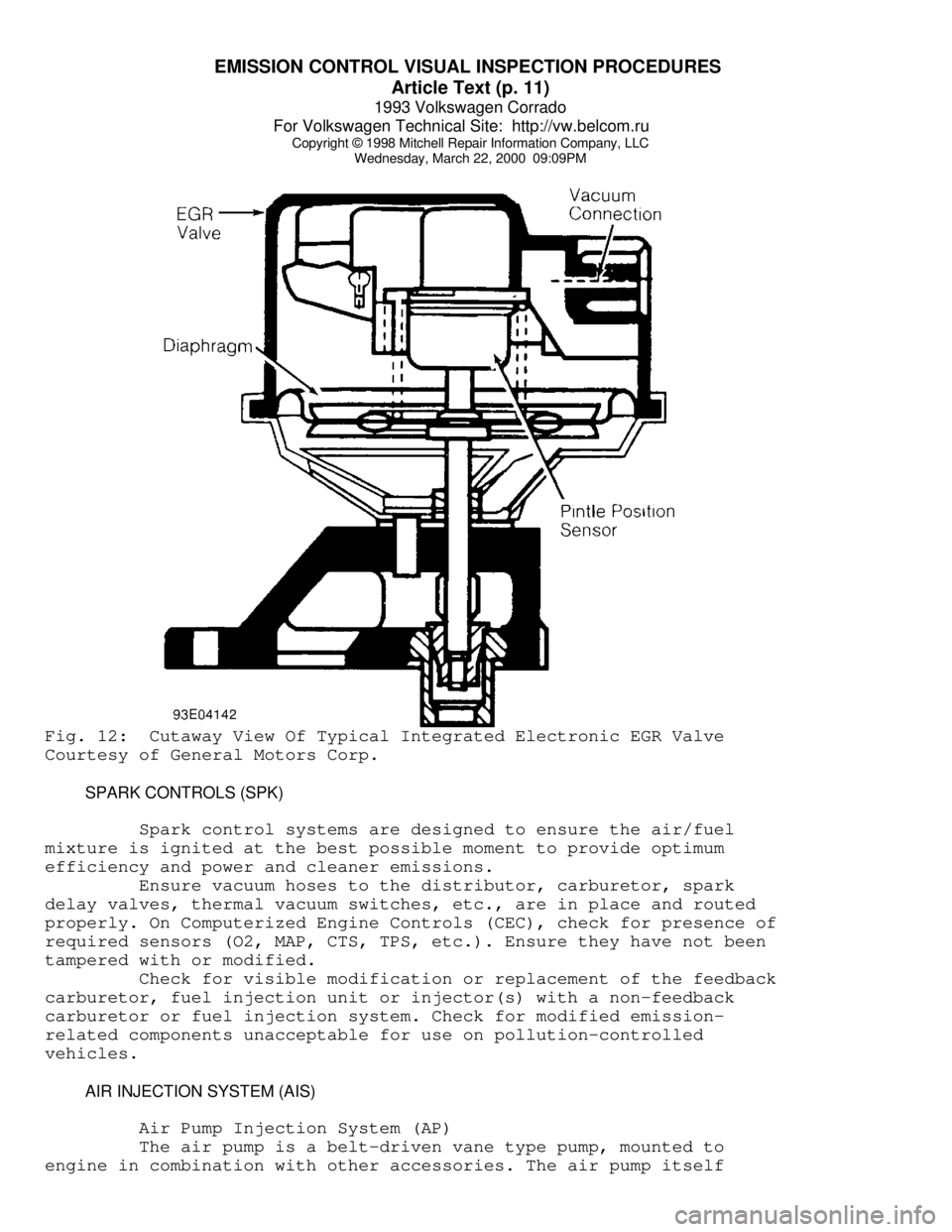
Wednesday, March 22, 2000 09:09PMFig. 12: Cutaway View Of Typical Integrated Electronic EGR Valve
Courtesy of General Motors Corp.
SPARK CONTROLS (SPK)
Spark control systems are designed to ensure the air/fuel
mixture is ignited at the best possible moment to provide optimum
efficiency and power and cleaner emissions.
Ensure vacuum hoses to the distributor, carburetor, spark
delay valves, thermal vacuum switches, etc., are in place and routed
properly. On Computerized Engine Controls (CEC), check for presence of
required sensors (O2, MAP, CTS, TPS, etc.). Ensure they have not been
tampered with or modified.
Check for visible modification or replacement of the feedback
carburetor, fuel injection unit or injector(s) with a non-feedback
carburetor or fuel injection system. Check for modified emission-
related components unacceptable for use on pollution-controlled
vehicles.
AIR INJECTION SYSTEM (AIS)
Air Pump Injection System (AP)
The air pump is a belt-driven vane type pump, mounted to
engine in combination with other accessories. The air pump itself
Page 527 of 920
EMISSION CONTROL VISUAL INSPECTION PROCEDURES
Article Text (p. 13)
1993 Volkswagen Corrado
For Volkswagen Technical Site: http://vw.belcom.ru
Copyright © 1998 Mitchell Repair Information Company, LLC
Wednesday, March 22, 2000 09:09PM
OXYGEN SENSOR (O2)
The O2 sensor is mounted in the exhaust system where it
monitors oxygen content of exhaust gases. Some vehicles may use 2 O2
sensors. The O2 sensor produces a voltage signal which is proportional
to exhaust gas oxygen concentration (0-3%) compared to outside oxygen
(20-21%). This voltage signal is low (about .1 volt) when a lean
mixture is present and high (1.0 volt) when a rich mixture is present.
As ECM compensates for a lean or rich condition, this
voltage signal constantly fluctuates between high and low, crossing a
reference voltage supplied by the ECM on the O2 signal line. This is
referred to as cross counts. A problem in the O2 sensor circuit should
set a related trouble code.
COMPUTERIZED ENGINE CONTROLS (CEC)
The CEC system monitors and controls a variety of
engine/vehicle functions. The CEC system is primarily an emission
control system designed to maintain a 14.7:1 air/fuel ratio under most
operating conditions. When the ideal air/fuel ratio is maintained, the
catalytic converter can control oxides of nitrogen (NOx), hydrocarbon
(HC) and carbon monoxide (CO) emissions.
The CEC system consists of the following sub-systems:
Electronic Control Module (ECM), input devices (sensors and switches)
and output signals.
EARLY FUEL EVAPORATION (EFE)
The EFE valve is actuated by either a vacuum actuator or a
bimetal spring (heat-riser type). The EFE valve is closed when engine
is cold. The closed valve restricts exhaust gas flow from the exhaust
manifold. This forces part of the exhaust gas to flow up through a
passage below the carburetor. As the exhaust gas quickly warms the
intake mixture, distribution is improved. This results in better cold
engine driveability, shorter choke periods and lower emissions.
Ensure EFE valve in exhaust manifold is not frozen or rusted
in a fixed position. On vacuum-actuated EFE system, check EFE thermal
vacuum valve and check valve(s). Also check for proper vacuum hose
routing. See Fig. 15.
Page 846 of 920

TROUBLE SHOOTING - BASIC PROCEDURES
Article Text (p. 55)
1993 Volkswagen Corrado
For Volkswagen Technical Site: http://vw.belcom.ru
Copyright © 1998 Mitchell Repair Information Company, LLC
Wednesday, March 22, 2000 09:26PM
Faulty choke Replace choke
assembly, see ENGINE
PERFORMANCE section
Clogged air filter Clean and/or replace
air filter
Incorrect idle speed or Reset idle speed and/
dirty carburetor or clean carburetor
Faulty ignition wires Replace ignition
wiring
Prolonged operation Shut engine off
at idle during long idle
Sticking valves or worn Check valve train
valve guide sealsÄÄÄÄÄÄÄÄÄÄÄÄÄÄÄÄÄÄÄÄÄÄÄÄÄÄÄÄÄÄÄÄÄÄÄÄÄÄÄÄÄÄÄÄÄÄÄÄÄÄÄÄÄÄÄÄÄÄÄÄÄÄÄÄÄÄÄÄÄÄWet Fouling Worn rings and pistons Install new rings and
or Oil Deposits pistons
Excessive cylinder wear Rebore or replace
block
Excessive valve guide Worn or loose bearing
clearance
ÄÄÄÄÄÄÄÄÄÄÄÄÄÄÄÄÄÄÄÄÄÄÄÄÄÄÄÄÄÄÄÄÄÄÄÄÄÄÄÄÄÄÄÄÄÄÄÄÄÄÄÄÄÄÄÄÄÄÄÄÄÄÄÄÄÄÄÄÄÄGap Bridged Deposits in combustion Clean combustion
chamber becoming fused chamber of deposits
to electrode
ÄÄÄÄÄÄÄÄÄÄÄÄÄÄÄÄÄÄÄÄÄÄÄÄÄÄÄÄÄÄÄÄÄÄÄÄÄÄÄÄÄÄÄÄÄÄÄÄÄÄÄÄÄÄÄÄÄÄÄÄÄÄÄÄÄÄÄÄÄÄBlistered Engine overheating Check cooling system
Electrode
Wrong type of fuel Replace with correct
fuel
Loose spark plugs Retighten spark plugs
Over-advanced ignition Reset ignition timing
timing see ENGINE PERFORMANCE
ÄÄÄÄÄÄÄÄÄÄÄÄÄÄÄÄÄÄÄÄÄÄÄÄÄÄÄÄÄÄÄÄÄÄÄÄÄÄÄÄÄÄÄÄÄÄÄÄÄÄÄÄÄÄÄÄÄÄÄÄÄÄÄÄÄÄÄÄÄÄPre-Ignition or Incorrect type of fuel Replace with correct
Melted Electrodes fuel
Incorrect ignition timing Reset ignition timing
see ENGINE PERFORMANCE
Burned valves Replace valves
Engine Overheating Check cooling system