turn signal VOLKSWAGEN GOLF 1993 1H / 3.G Owners Manual
[x] Cancel search | Manufacturer: VOLKSWAGEN, Model Year: 1993, Model line: GOLF, Model: VOLKSWAGEN GOLF 1993 1H / 3.GPages: 156, PDF Size: 6.36 MB
Page 5 of 156
Downloaded from www.Manualslib.com manuals search engine CONTROLS AND EQUIPMENT
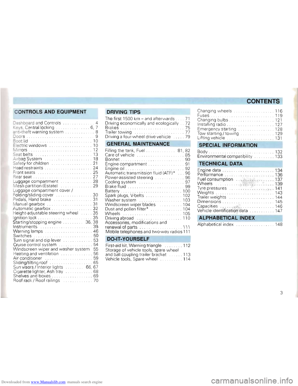
Dashboard and Controls ..... 4
. ey s, Cen tral locking . . .... 6, 7
::"tl-thef t warning system .... 8
Joors .......................... .... 9
oot lid .... ........... . . . . . 10
::Iectric windows .. . .. 10
• ~Irrors . . ..... . ... 12
Seal belts 13
"" rbag System . . . . . 18
Safe ty for children .. ... 21
ead restraints . . . . . .. 24
= ro nt seats . . . . . . . . . . . .. 25
Rear seat . . . 27
L u ggage compartment ... . ... . ...... 28
M esh partition (Estate) ...... 29
L u ggage compartment cover /
F olding/sliding cover
... 30
Pedals, Hand brake .. 31
Manual gearbox .... ... .... 31
Automati c gearbox . . . .. .......... 32
H eig ht-adjustable steering wheel ..... 35
I gnition lock. . . . . .. 35
Starting/stopp ing engine 36, 38
\lIstrumellts .. .... 39
Warning lamps ....... 46
Switches . . . . . . . . . . . . . . 50
Turn signal and dip lever ............. 53
Cruise control system ........... 54
Wi ndscreen wipe r and washer system 55
Heating an d ventilation .. . ...... 56
Air cond itioner ......' 59
Sliding/ti ltin g roof. . . . . . . . . . . . ... 65
Sun visors / Interior lights 66,67
Cigarette lighter, Ash tray ..... 68
Shelves and boxes . . . . . . . . . . . ... 69
Roof rack / Roof ra ilings ... 70
DRIVING TIPS
The firs t 1500 km -and after wards .... 71
Driving economically and ecologically .. 72
Brakes. . . . . . . . . . . . . . . . 75
Tra iler tow ing . .. ..... . .... ... ...... 77
Driving a four- wheel drive vehicle .. 79
GENERAL MAINTENANCE
Filling the tan k, Fuel. 81, 82
Care of vehicle ........ .. . . 85
Bonnet . . ... 90
Engine compartment .. ...... .... .... 91
Engine oil ..... .......... ........... 92
Automatic transmission fluid (ATF)* ... 96
Power-assisted steering .. 96
Cooling system . . . . . . . . . . .. . 97
B rake fluid ...... 99
Battery . . . . .. 100
Spark plugs. V-belts . . . . . . . . . 102
Washer system
... . .. 103
Windscreen w iper blades . . . 104
Dust a
nd pollen filter * . 104
Wheel s . 105
D riving abroad ..... ............... 110
Accessories, modifications and
renewa l ot parts .............. III
Mobile telephones and tw o-way rad ios 111
DO -lT-YOURSELF
First -aid kit, Warn ing triangle ........ 112
Storage of vehicle tools, spare wheel
a n d ball coupling trailer bracket ...... 113
Vehicle tools, Spare wheel 114
CONTENTS
Changing w heels . 116
F uses . ........ .. .. . . . ... . .... 119
Changing bulbs. . .... .. . 121
Installing radio . . . . .. 127
E mergency starting .. .. 128
Tow starting / to wing . . .. 129
L ift ing vehicle ......... 131
SPECIAL INFORMATION
Body ..... .... . .......... 132
Environmental compatibility ... 133
TECHNICAL DATA
Engine data . .. , .... .... . 134
P er forman ce .. ... ... ... . .. 136
Fuel consump tion .. 137
Wh eels
. . 139
T yre pressures
.. .. ... .. . . .. ... 1 4 1
Weights ... 143
Trailer weights .. 144
Dimensions. ...... .. ... 145
Capacities " ..... 146
Vehicle identification data ... 147
ALPHABETICAL INDEX
Alph abetical index ... 148
3
Page 7 of 156
Downloaded from www.Manualslib.com manuals search engine __CONTROLS AND EQUIPMENT
Page
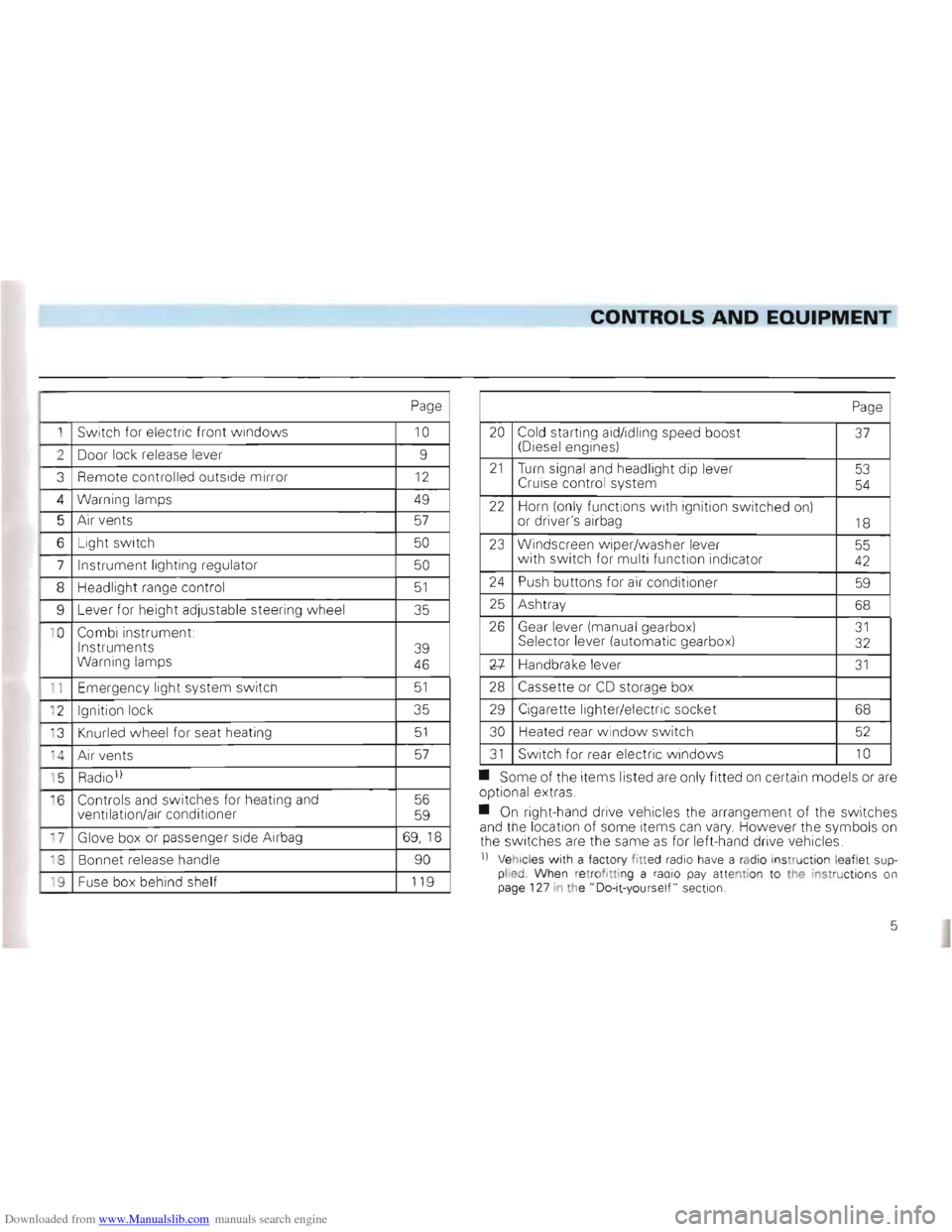
1 Switch for electric front windows 10
2 Door lock release lever 9
3
Remote controlled outside mirror 12
4 Warning lamps 49
5 Air vents 57
6 Light switch 50
7 Instrument lighting regulator 50
8 Headlig ht range control 51
9 Lever for heig ht adjustable steeri ng w heel 35
1 0
Combi instrument:
Instruments
Warning lamps
39
46
1 1 Emer gency light system switch 51
' 2 Ignition lock 35
' 3
Knurled wheel for seat heating 51
'4 A ir ve nts 57
' 5 Radio 1)
·6 Controls and switches for heating and
ventilation/air conditioner 56
59
17 Glove box or passenger side Airbag 69,1 8
18 Bonnet release handle 90
'9 Fuse box behind shelf 119
Page
20 Cold starting aid/idling speed boost (Diesel engines) 37
21 Turn signal and headlight dip lever
Cruise control system 53
54
22 Horn (on ly functions with ign ition switched on)
or driver's airbag 18
23 Windscreen w iper/washer lever
w ith switch for multi function indica tor 55 42
24 Push buttons for air conditi oner 59
25 Ash tray 68
26 Gear lever (manua l ge arbox) Sel ector lever (automa tic gea rbox) 31 32
Xl-Handbrake leve r 31
28 Cassette or CD storage box
29 Cigarette lighter/elec tric soc ket 68
30
Heated rear windo w switch 52
31 Switch for rear electric w indows 10
• Some of the items listed are only fitted on certain models or are op tional extras .
• On right-hand drive vehicles the
arrangement of the switches
and the location of some items can vary. However the symbo ls on
th e switc hes are the same as for left-hand drive vehic les.
n Vehicl es with a facto ry fitted radio have a rad io ins truction le aflet supplied Whe n re trof ittin g a radio pay atte ntion to the instructions on
page 127 in the" Do-it-yours elf " sect ion.
5
Page 10 of 156
Downloaded from www.Manualslib.com manuals search engine CONTROLS AND EQUIPMENT
Anti-theft warning
system*
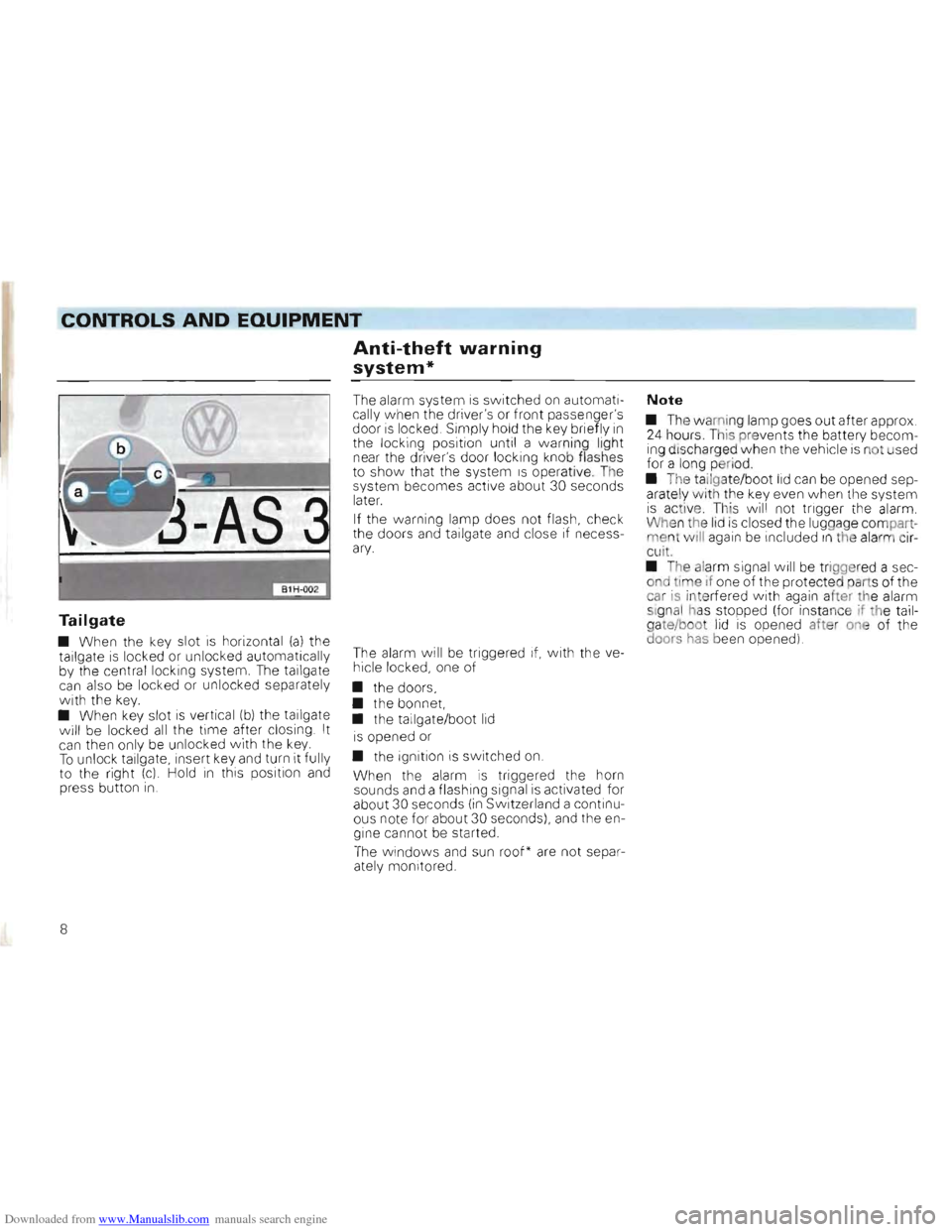
Tailgate
• When the key slot is horizont al (a) the
tailgate is locked or unloc ked automatically
by the central locking system. The tallgate can also be locked or unloc ked separately with the key. • When key slot is vertical (b) the tailgate
will be locke d all the time after closing . It can the n only be unlocked with the key. To unlock tailgate , insert key and turn It fully
to the right (c) Hold in this position and press button in .
The alarm system is switched on automatically when the driver's or front passenger's door is locked. Simply hold the key briefly in the locking position until a warni ng light
near the driver's door locking knob flashes
t o show that the system IS operative. The
system becomes active about 30 seconds
lat
er.
If the warning lamp does not flash, check
the doors and tailgate and close if necessary.
The alarm will be triggered if, with the ve
hicle locked, one of
• the doors,
• the bonnet,
• the tailgate/boot
lid
is opened or
• the ignition is switched
on.
When the alarm is triggered the horn
sounds and a flashi ng signal is activated for
about 30 seconds (in Switz erland a continu
ous note for about 30 seconds), and the en
gine cannot be started .
The windows and sun roof* are not separ
ately monitored .
Note
• The wa mi ng lamp goes out after approx . 24 hours. T hiS pre ven ts the battery becom
ing disc harged when the vehicle is not used for a long peri od
• The
tailgate/boo t lid can be opened sep
arate ly wi th the key even w hen the system is active . This wi ll not trigger the alarm .
Whe n the lid is closed the luggag e compartment wili again be included In the alarm circu it.
•
The alarm signal will be triggered a sec
ond time if one of the protecte d part s of the
car
is inte rfered w ith again aher th e alarm
si gnal has stopped (for insta nce if the tailgate/boo t lid is opened after one of the
doors has been opened)
8
Page 48 of 156
Downloaded from www.Manualslib.com manuals search engine CONTROLS AND EQUIPMENT
Warning lamps
Attention • Be careful when opening the coolant expansion tank! When the engine is hot the cooling system is under pressure -Danger of scalding! Let engine cool down therefore before unscrewing the cap_
• Do not touch the fan. The fan can switch on suddenly -even when ignition is switched off.
For furthe r details see pages 98 and 98.
1 -Coolant temperaturel _~_ If the coolant le vel is in orde r the trouble Coolant level') may be due to failure of the radiato r fan.
Check radiator fan fuse and renew is
T he wa rni ng lamp lights up for a few sec
necessary -see page 119.onds as a functional check when ign ition IS coo lant level .
. 46 switched on.
2 - Engine oil pressure ... .. 47 If the warning lamp does not go out al
If the lamp does not go out afterwards or 3 -Alternator . 47 though coolant level and fan fuse are inflashes when driving, either the coolant 4 -Glow plugs ... 47 orde r, do not drive on -call in expe rt astempe ratur e is too high or the coolant 5 -Brake system .. 48 sistance
.
level1 l too low: 6 -Brake pad wear indicator .48 If the trouble is only caused by the fan andStop, switch engine off and check7 -Turn signals 48
assuming coolant level is in order and temlevel . Add coolant if necessary . 8 -Main beam .
48
perature warning lamp is out -one can drive on to the nearest Volkswagen dealer. In 11 Only 011 vehicl es wi h a t omatic coolant order to make good use of the air stream for level lllonit or (see page 97 l. cooling , do not let engine idle or drive very
slowly .
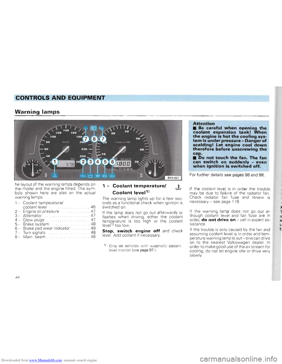
he
layout
of the warning lamps depends on the model and the engine fitted. The sym
bols shown here are also on the actual
warn ing lamps.
1 -Coolant temperature /
Page 50 of 156
Downloaded from www.Manualslib.com manuals search engine CONTROLS AND EQUIPMENT
5 -Brake system
(CD)
The warning lamp* co mes on when
• the handb rake is
on • the brake fluid level is too low The ignition must be switched on.
Attention
If the lamp does not go out when handbrake is released or comes on when driving, the fluid level in the reservoir is too low. Immedi
ately contact a Volkswagen dealer and have the brake system
examined.
You can drive on carefully to the
nearest Volkswagen dealer but allow for higher pedal pressures and longer braking distances on
the way.
I6 -Brake pad wear I,'0',
indicator*
The wa rning lamp lights up for one second when the ignition is switched on as a func
tiona l check.
If the lamp then does not go out or it lights
up dur ing the Journey , the front brake pads
are worn. You should visit a Volkswagen
dealer to have the brake pads checked.
As the brake pad wea r indicator only moni
t ors the front brake pads, we recommend
that you have the rear brake linings checked as well.
7 -Turn signals
The warn ing lamp flashe s when turn signals are sWitched on. If a turn signal fails, the
warning lamp flashes tw ice as fast. (Not
w hen towing a trailer )
Fur ther details are given
on pages 49 and 53.
8 -Main beam
The warning lamp come s on when th e main
beam is on or when the headligh t flas her is used.
48
Page 51 of 156
Downloaded from www.Manualslib.com manuals search engine ----CONTROLS AND EQUIPMENT
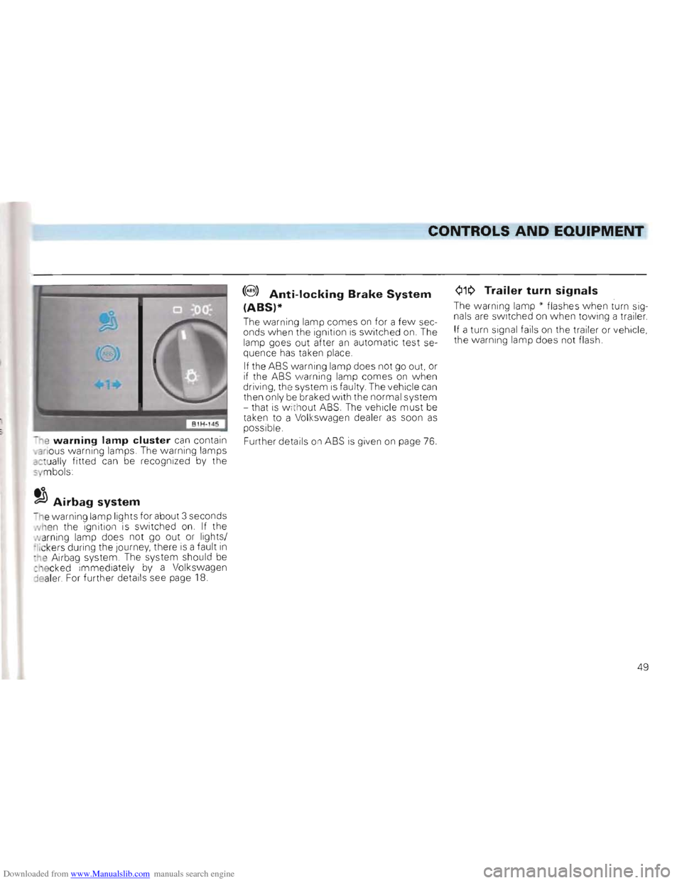
Q1~ Trailer turn signals(8 ) Anti-locking Brake System
(ABS)* The warning lamp" flashes when turn sig
nals are switched on when towing a trailer. The warning lamp comes on for a few sec
onds when the ignition is switched on. The If a turn signal fai ls on the trailer or vehicle,
lamp goes out after
an automatic test se the
warning lamp does not flash.
quence has taken place,
If the ASS warning lamp does not go out. or if the ASS warning lamp comes on when
driving, the system is fau lty The vehicle can then only be braked with the normal system
- that is w ith out ASS. The vehicle must be taken to a Vol kswagen dealer as soon as possible .
- ne
warning lamp cluster can contain Further details on ASS is given on page 76 . •anous warning lamps. The warning lamps actually fitted can be recognized by the 5 mbols
to ~Airbag system
n e warning lamp lights for about 3 seconds Nhen the ignition is switched on. If the
N arning lamp does not go out or lights/
;Iickers during the Journey, there is a fault in :he Airbag system , The system should be ct16cked immediately by a Volkswagen
:lealer For further details see page 18.
49
Page 55 of 156
Downloaded from www.Manualslib.com manuals search engine CONTROLS AND EQUIPMENT
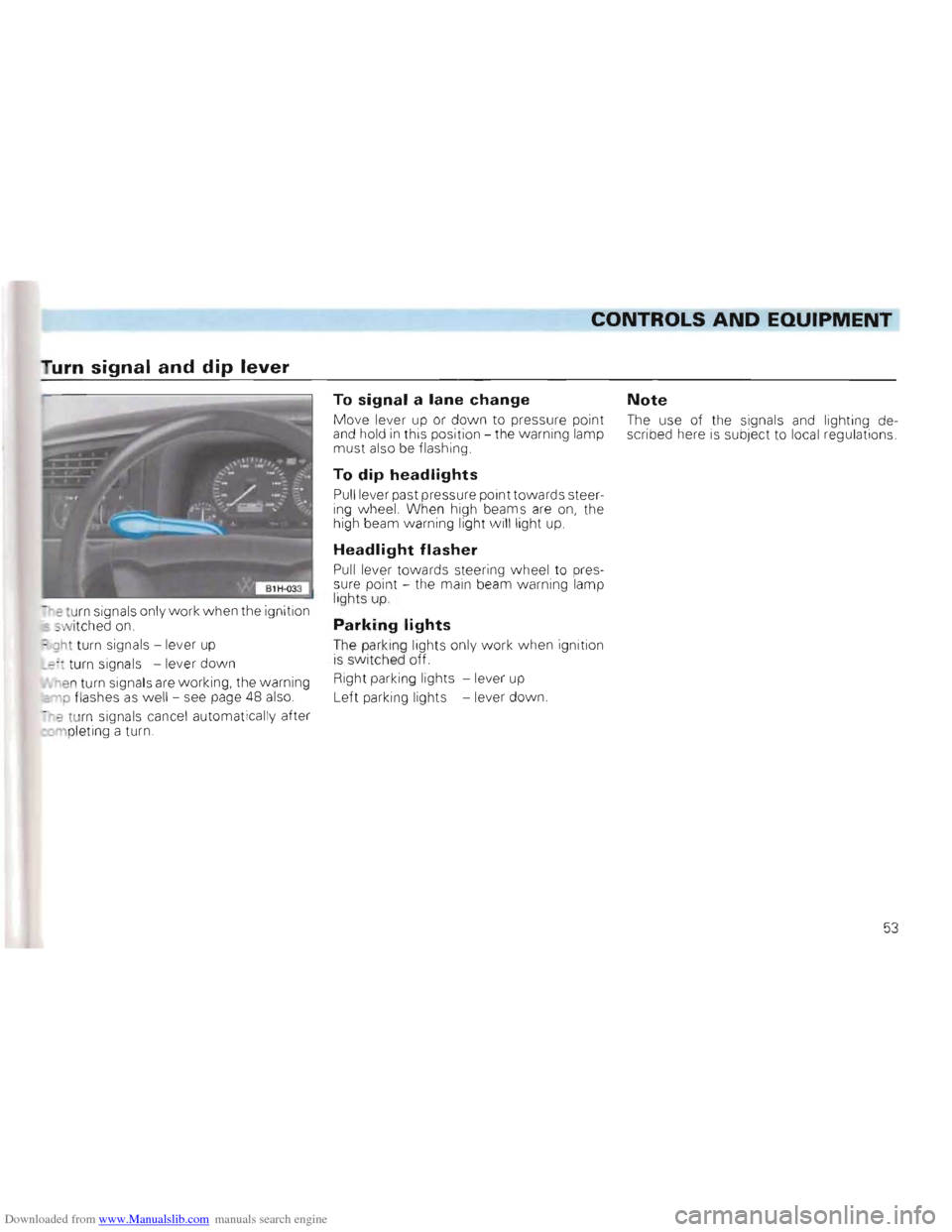
Tu rn signal and dip lever
~eturn sign als only w ork when the ignition -wit ched on.
~ gh t turn signa ls -lever up
_z turn signa ls -lever down
"en turn signa ls are working, the warning
p flashes as well - see page 48 also.
-'? tur n signa ls cance l automatica lly after rnplet ing a turn
To signal a lane change Note
Move le ve r up or do w n to pres sure point The use of the signals and lighting deand hold in th is position the w arning lamp
scribed he re is subje ct to local regu lations
must also be f lash ing
To dip headlights
Pull le ve r past pressure point towards steering w heel. When high beams are on, the
high beam warning lig ht w ill light up
Headlight flasher
Pull lever towards steeri ng wh eel to pres
sure poin t - the main beam wa rning lamp
light s up .
Parking lights
The park ing lights on ly work when ignition is s w itched off.
Right park
ing lights -lever up
L
eft park ing li ghts -lever dow n.
53
Page 56 of 156
Downloaded from www.Manualslib.com manuals search engine ------------------------------------------------CONTROLS AND EQUIPMENT
Cruise control system *
To relieve the foot on the accelerator pedal
this system can hold any speed above about
35 km/h (20 mph) constant, so long as en
gine output permits.
Attention The cruise control system should not be used in dense traffic and poor road conditions (slippery surfaces, aquaplaning, gravel).
When system is switched on do not move into neutral without depressing the clutch pedal, otherwise the engine will race and can, under certain circumstances, become damaged.
•
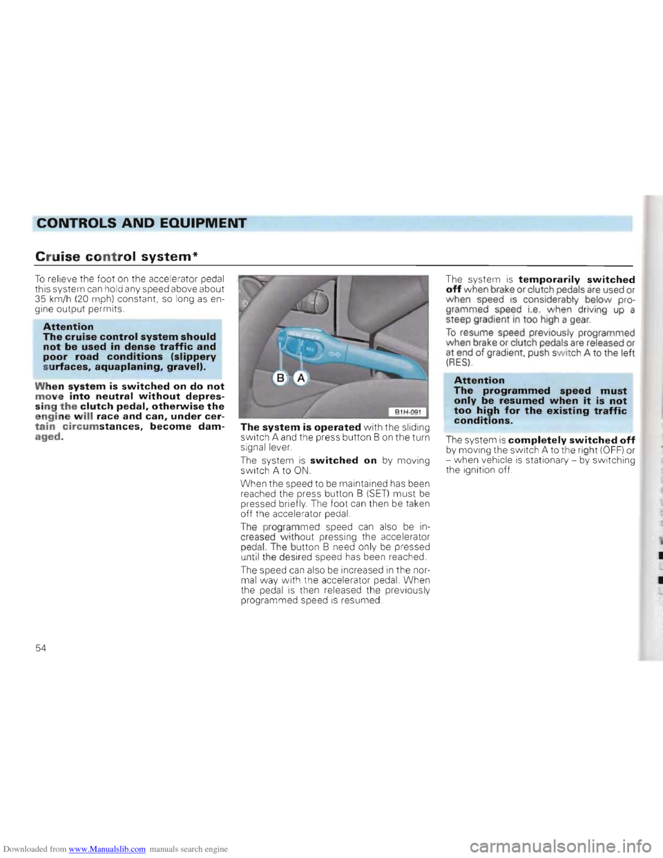
The system is operated with the sliding
switch A and the press button B on the turn
signal lever.
The system
is switched on by moving
switch A to ON.
When the speed to be maintained has been
reached the press button B
(SET) must be pressed briefly The foot can then be taken off the accelerator pedal
The p
rogrammed speed can also be in
creased w ithout pressing the accelerator
p ed
al. The button B need only be pressed
u ntil the desired speed has been reached.
T he speed
can also be increased in the normal way with th e accelerator pedal. When
the pedal is then releas ed the previously
pro gra m m ed speed is resumed
The system is temporarily switched off when brake or clutch pedals are used or when speed IS cons ide rably below pro
grammed speed i.e. whe n driving up a
steep gradient
in too high a gea r.
To resume speed previo u sly programmed
when brake or clutch pedals are re leased or at end of gradient, push sWit ch A to the left (RES)
Attention The programmed speed must only be resumed when it is not too high for the existing traffic conditions.
The system is completely switched off by moving the switch A to the righ t (OFF) or
-when vehicle is stationary -by switching
the ignition off.
54
Page 126 of 156
Downloaded from www.Manualslib.com manuals search engine DO-lT-YOURSELF
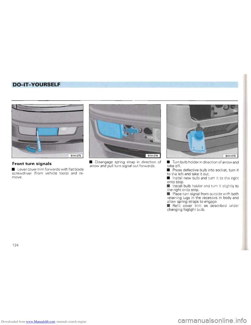
• Disengage spring strap in direct ion of Front turn signals arro w and pull turn signa l out forwards .
• Lever cover trim forwards w ith flat blade
scre
wdri ver (from vehicle tools) and re
move.
• Turn bulb holder in direction of arro w and
tak e off.
•
Press defec tive bulb into socket, turn it
to the left and take it out .
• Insta
ll new bulb and turn it to the right
on to stop.
• Install bulb holder and turn it slight ly to th e r igh t ont o stop.
• Place tu
rn sign al fr om outside with both
retainin g lugs in the rec esse s in body and
allo w spring straps to engage
• Refi t cov er tr im
as d e sCi"lbed under
chang in g fogl ight bUlb.
124
Page 127 of 156
Downloaded from www.Manualslib.com manuals search engine DO-lT-YOURSELF
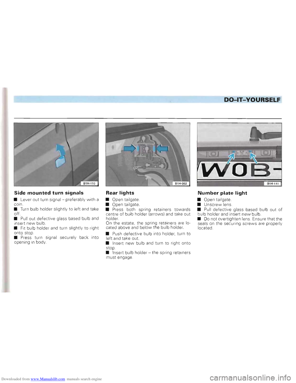
Side mounted turn signals
• Lever out turn signa l - preferab ly with a
coin.
•
Turn bulb holder slightly to left and take off.
• Pull out defective glass based bu lb and i nsert new bulb.
• Fit bulb holder and turn slightly to right
onto stop.
• Press turn signal securel y
back into
openin g in body
Rear lights
• Open tailgate.
• Open tailgate.
• Press both spring retainers towards
centre of bulb holder (arrows)
and take out
holder.
On the estate , the spring retainers are lo
cated above and below the bulb holder.
•
Push defecti ve bulb into holder , turn to
left and take out.
• Insert
new bulb and turn to right onto
stop .
•
Inser t bulb holder -the spring retainers
mus t engage.
Number plate light
• Open tailgate.
• Unscrew lens.
•
Pull defective glass based bulb out of bu lb holder and insert new bu lb.
• Do not overtighten lens . Ensure that the
seals on the secur ing screws are properly
located .