buttons VOLKSWAGEN GOLF 1993 1H / 3.G Owners Manual
[x] Cancel search | Manufacturer: VOLKSWAGEN, Model Year: 1993, Model line: GOLF, Model: VOLKSWAGEN GOLF 1993 1H / 3.GPages: 156, PDF Size: 6.36 MB
Page 7 of 156
Downloaded from www.Manualslib.com manuals search engine __CONTROLS AND EQUIPMENT
Page
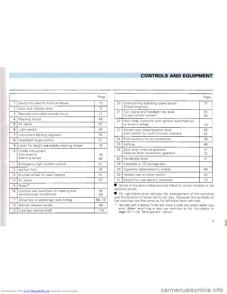
1 Switch for electric front windows 10
2 Door lock release lever 9
3
Remote controlled outside mirror 12
4 Warning lamps 49
5 Air vents 57
6 Light switch 50
7 Instrument lighting regulator 50
8 Headlig ht range control 51
9 Lever for heig ht adjustable steeri ng w heel 35
1 0
Combi instrument:
Instruments
Warning lamps
39
46
1 1 Emer gency light system switch 51
' 2 Ignition lock 35
' 3
Knurled wheel for seat heating 51
'4 A ir ve nts 57
' 5 Radio 1)
·6 Controls and switches for heating and
ventilation/air conditioner 56
59
17 Glove box or passenger side Airbag 69,1 8
18 Bonnet release handle 90
'9 Fuse box behind shelf 119
Page
20 Cold starting aid/idling speed boost (Diesel engines) 37
21 Turn signal and headlight dip lever
Cruise control system 53
54
22 Horn (on ly functions with ign ition switched on)
or driver's airbag 18
23 Windscreen w iper/washer lever
w ith switch for multi function indica tor 55 42
24 Push buttons for air conditi oner 59
25 Ash tray 68
26 Gear lever (manua l ge arbox) Sel ector lever (automa tic gea rbox) 31 32
Xl-Handbrake leve r 31
28 Cassette or CD storage box
29 Cigarette lighter/elec tric soc ket 68
30
Heated rear windo w switch 52
31 Switch for rear electric w indows 10
• Some of the items listed are only fitted on certain models or are op tional extras .
• On right-hand drive vehicles the
arrangement of the switches
and the location of some items can vary. However the symbo ls on
th e switc hes are the same as for left-hand drive vehic les.
n Vehicl es with a facto ry fitted radio have a rad io ins truction le aflet supplied Whe n re trof ittin g a radio pay atte ntion to the instructions on
page 127 in the" Do-it-yours elf " sect ion.
5
Page 14 of 156
Downloaded from www.Manualslib.com manuals search engine CONTROLS AND EQUIPMENT
Mirrors
Adjusting mirrors
The rear view mirrors should always be ad
j u sted properly before moving off so that
good vision to the rear
is obtained.
Anti-dazzle inside mirror
The leve r on the lower edge of the mirror
s hou ld be pointing to the rear when the
basic setting is made.
To set the anti-dazzle position, push lever
forwards .
Exterior mirrors controlled mechanically from inside are adjusted wi th the
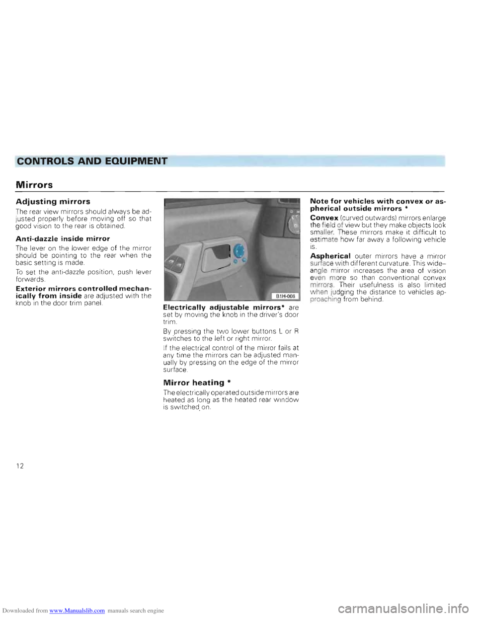
knob in the door trim panel. Electrically adjustable mirrors· are
set by moving the knob in the driver's door
trim .
B y pressing the
two lower buttons L or R switche s to the left or right mirror.
I f the electrical
contro l of the mirror fails at
any time the mirrors can be adjusted man
uall y by pressing on the edge of the mirror
surface.
Mirror heating *
The electrically operated outside mirrors are heated as long as the heated rear Wi ndow is switched. on.
Note for vehicles with convex or aspherical outside mirrors •
Convex (curved outwa rds) mirrors enlarge
th e field of view but they make objects look
sm aller. These mirrors make it difficult to
e stimate h
ow far away a following veh icle IS .
Aspherical outer mirrors have a mirror
surface vlfith different curvature. This wideangle mirror increases the area of vis ion e en more so than conventional convex
mirrors . The ir usef ulness is also li mi ted
" hen Judging the distan ce to vehicles ap
proaching from behind.
12
Page 43 of 156
Downloaded from www.Manualslib.com manuals search engine CONTROLS AND EQUIPMENT
2 -Analog clock
--e th e time there is a button below the
_ -(right arrow):
• -pr esse d briefly , the
time is advanced one minute.
• pressed continuous ly the minute hand
ss fa ster and the hours are set as well.
;h the button the clock can be set exactly
- h e second :
• Press button until
time is one minute be.,re ti me to be set.
• ress button at the
moment when the
_ =f'"on ds indicator of an accurate clock -~ows a full minute or when the time signal
s eard on the radio.
2-Rev counter *
- e rev counter needle mu st not move into
e red zone of the sca le on any account.
~Changing up in good time helps ~,) to save fuel and keeps the noise down.
_hange down to the next lower gear before ~"e engine starts labouring or no longer runs
l oothly.
rin g the running-in period, high engine ' 9VS should be avoided.
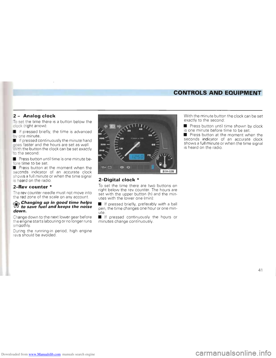
2-Digital clock *
To set the time there are tw o buttons on right below the re v counter . The hours are
set with the upper button (h) and the min
utes with the lower one (min) :
•
If pressed briefly, preferably w ith a ball
pen, the time changes one hour or one min
ute.
• If pressed continuous ly the hours or
m inutes change continuous ly . With
the minute button the clock
can be set
exactly to the second:
• Press button until
time shown by clock is one mi nute before time to be set.
• Press button at the moment w he n the
seconds indicator of an accurate clock
shows a fu ll minute or when the time signa l
i s heard on the radio.
41
Page 62 of 156
Downloaded from www.Manualslib.com manuals search engine • •
CONTROLS AND EQUIPMEN.-=T-""------__________________
Air recirculation should only be selected for short periods of time as no fresh air is taken in in this mode and the windows can steam up if the air conditioner is switched off.
Note
Buttons D and E can be pressed In conjunc
tion w ith one another .
Air vents
Depending on the position of rotary regula
tor B heated or unhea ted fresh air or coo led
air flows from all vents.
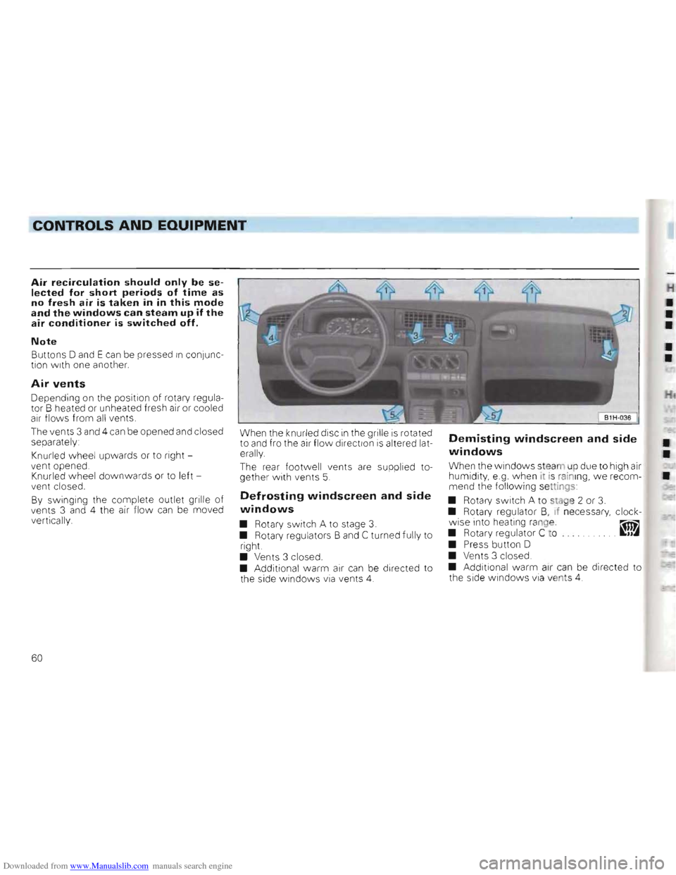
The vents 3 and 4 can be opened and closed
separately :
Knurled wheel upwards
or to right
vent opened .
Knurled
wheel downwards or to left
ven t closed.
By swinging the complete outlet grille of
vents 3 and 4 the air flow ca n be moved
vertically.
W hen the knurled disc in the grille is rota ted
to and fro the air flow direction is altered lat
erally
The
rear footwell vents are supplied to
gether with vents 5.
Defrosting windscreen and side
windows
• Rotary switch A to stage 3.
• Rotary regu lators Band C turn ed fully to
right.
• Vents 3 closed .
• Additional warm a
ir can be directed to
the side windows via vents 4.
Demisting windscreen and side
windows ••When the windows steam up due to high air
humidity, e.g. when it is rain ing, we recom•mend the following settings
• Rotary switch A to stag e 2 or
3. • Rotary regulator B, if necessary, clock
wise into heating range. ~
• Rotary regu lator C to . JJ~
• Press button D
• Ve nts 3 closed.
• Additiona l warm air can be directed to
th e sid e windows via vents 4.
60
Page 64 of 156
Downloaded from www.Manualslib.com manuals search engine CONTROLS AND EQUIPMENT
•
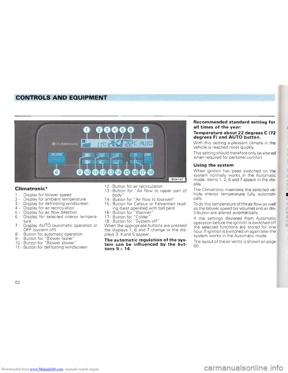
Climatronic*
1 - Display for blower speed
2 - Display for ambient temperature
3 - Display for defrosting windscreen
4 - Display for
air recirculation
5 - Dis play for air flow direction
6 - Displa y for selected interior tempera
ture
7 -
Display AUTO (automatic operation or OF F (system off)
8 - Button for automatic operation
9 - Button for "Blo
wer faster" 10 -Button for "Blower slower" 11 - Button for defrosting windscreen
12 -Button for air recirculation 13 -Button for "Air flow to upper part of body" 14 -Button for " Ai r flow to footwell " 15 -Button for Celsius or Fahrenheit reading (best operated with ball pen)
16 -Button for "Warmer" 17 -Button for "Colder" 18 -Button for" System off" When the appropriat e buttons are pressed
the disp lays 1, 6 and 7 change or the displays 3, 4 and 5 appear.
The automatic regulation of the system can be influenced by the buttons 9 -14.
Recommended standard setting for
all times of the year:
Temperature about 22 degrees C (72
degrees F) and AUTO button.
With this setting a pleasant climate in the
vehicle is reached most quickly
This setting should therefore only be alt ered
when required for personal comfort.
Using the system
When ignition has been swi tc hed on the
system normally works in the Automatic
mode. Items 1, 2, 6 and 7 appear in the display.
The Clim atronic maintains the selected vehicle interior temperature fully automati
cally.
To do this temperature of the air flow as well as the blower speed (air volume) and air dis
tribution are altered automat ically.
If the settings deviate d fr om Automatic
operation before the ignition is switched off
the selected functions are stored for one hour. If ignition is switched on again later the
system works in the Automatic mode.
The layout of the air vents is show n on page 60.
62
Page 65 of 156
Downloaded from www.Manualslib.com manuals search engine 2
CONTROLS AND EQUIPMENT
r Notes on Automatic mode
• The interior temperature can be freely
s e lected w ith buttons 16 and 17 and is S ored alw ays until another temperature is selected , -he interior temperature can be set be
-we an + 18°C (64°F) and + 29°C (86°F) In th iS range it is automatically regulated,
f tempe ratures below 18°C are selected
LO" appears in the display , With tempera
-res abo ve 29 °C (86 ° Fl. "HI " is displayed ,
., these two end positions the system
N or ks continuous ly at ma ximum cooling or
n eating output. The temperatu re is not
r egulated
•
In certain operating con ditions it may be fo und that the syste m temporarily carries
o ut functions which are not quite as ex
5-pe cted, This includes, for examp le, that for
a few seconds after sta rting from cold, air is directed mainly into the fo ot wel l. This is ntentional so that damp air in the sys tem
d oes not cause the windo ws to mist up ,
Deviating from Automatic mode
In nearly all cases the Automatic mode
offers the best conditions for the comfort of
the vehicle occupants all the year round,
I n isolated cases however it might
be necessary to deviate from some functions
of Automatic mode by pressing certain but
tons, The Climatronic still works fu lly auto
matically
• With buttons 9 and 10 the blo w er speed
and thus the air vo lume can be increased or
r educed, Th is is sho wn by a change in the
number of lin es in display field 1
• With
bu tton 11 the de-humidifying and defrosting effect for the windsc reen can be
increased if, for example persons w ith
damp clothing
are picked-up shortly after
moving off,
• W ith button
12 air recircu lation can be
se lected to pre vent for examp le dust or
st rong smells
from entering the vehicle in
terio
r. At ambient temperatures below 5cC the sy ste m auto mat icall y sw itches off, This can lead to the window misting u p as t he air is no longer de-humidified.
Note
Smoking should be avoided when air recirculation is selected as t h e smoke drawn in from the vehicle interior deposits on the
evaporator of the air conditioner, This leads
to permanent odours when the air condition
is in operation These can only be efiminated b
y e xchanging the evaporator, which is
time-consuming
and expensive.
• With buttons
13 and 14 the air flow can
be to the upper part of the body or into the
footwe ll,
The air distribution buttons 11, 13 and 14
can be used in combination ,
• With button
18 (OFF) the complete sys
tem is sw itched off, This button should only
be pre ssed in isol ated cases eg when
the re is a fault in the system .
Wh en th e sp ecial functions are no longer re
quired the Automatic mode should be
s w itch ed on again without delay by pres
sin g the AUTO button,
63
Page 66 of 156
Downloaded from www.Manualslib.com manuals search engine CONTROLS AND EQUIPMENT
Operating instructions
• Ensure that the sensor betvveen the
windscreen defrost outlets in the centre of
the instrument panel and the air grille next
to the radio is not covered.
• If, after switching on the ignition,
all sym
bols in the display area flash for about 15
seconds, there is a fault in the system -con
tact a Volkswagen dealer.
Notes for both air conditioning
systems
• To ensure that the heating, ventilation
and air conditioner can work properly, the air
inlet in front of the windscreen should be
kept free of ice, snow and leaves.
• The heat output depends
on the coolant
temperature -the full heat output is there
fore available when the engine IS warm.
• The stale air escapes through openings
in the luggage compartment side panels.
Therefore when loading the luggage com
partment ensure that the openings are not
covered .
• When the ambient temperature
is high
and the air very humid, condensed water can drip off the evaporator and form a
puddle under the vehicle. This is quite nor
mal and does not indicate a leak.
Notes for the normal air condi
tioner
• All controls except the rotar y switch A and buttons 0 and E can be set to any inter
mediate position.
•
To prevent the windows from misting up
the blower should be running slowly when driving at low speeds.
Using air conditioners economi
cally
In cooling operation the air conditioner com
pressor places demands on the engine and
therefo re influences the fuel consumption.
To keep the period switched on as short as possible, the following points should be
noted:
• If the
in side temperature is very high
after the car has been parked in the sun, it is recommended to open doors or windows briefly to enable the hot air to escape
• The air conditioner should not be
switched on during a Journey if the
windows or sliding/tilting roof* are open.
• If the desired interior temperature
can be attained w ithout switching on the air
cond itioner the fresh air operation should
be selected (does not apply to Climatronicl.
Operating faults
• Should the air cond i:ioner not work at
any time, either .
- the ambient temperatu re IS below about +5 °C,
-or the fuse has blown.
Check fuse and if necessary r
enew it - see
page 119. If the troub le is n ot due to a defec
tive fuse, SWitch the system off and have It
checked.
- the air conditioner
has svvitched off due
to coolant temperature being too high -see
page 45.
• If the cooling output drops off, switch
the AlC
off and have the system checked.
64