bolt VOLKSWAGEN GOLF PLUS 2007 Owners Manual
[x] Cancel search | Manufacturer: VOLKSWAGEN, Model Year: 2007, Model line: GOLF PLUS, Model: VOLKSWAGEN GOLF PLUS 2007Pages: 541, PDF Size: 98.86 MB
Page 151 of 541
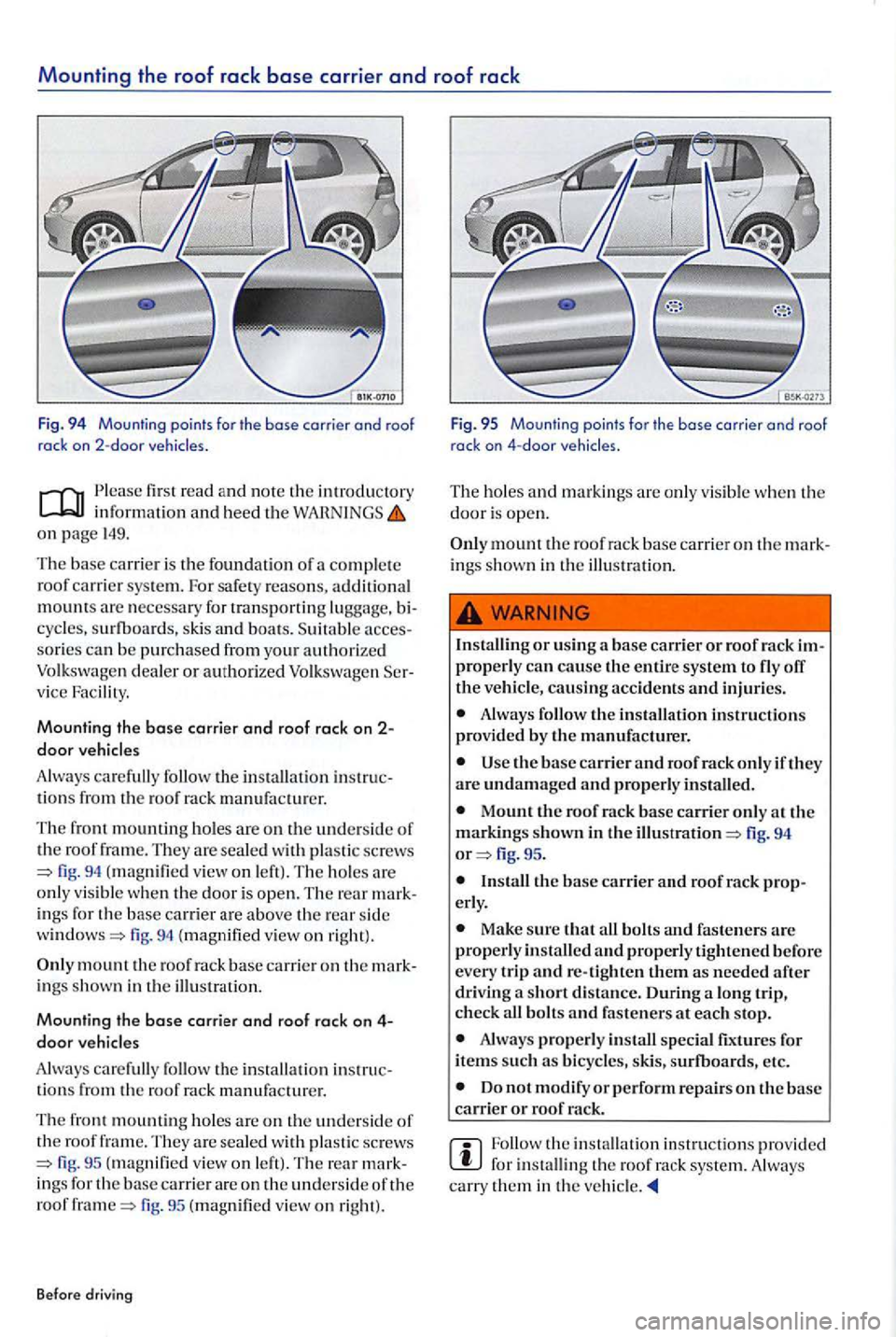
Mounting the roof rack base carrier and roof rack
Fig. 94 Mounting points for the base carrier and roof
rack on 2-door
first read and note the in troduc tory information and heed the on page 149.
Th e base carrier is the foundat i
on of a co mpl ete roof carrier syste m . For safe ty reasons, additio n al
mo unts necessary for transporting luggage, bi
cy cles, su rfb oards, skis and boats. acces
sories be purchased from your authorized Volkswage n dealer or a uthori zed Volkswagen
th e installat io n instru c
tions from the roo f rack manufa cturer.
The fr o nt mounting ho les are on th e underside of the roof frame. They are with pla stic screws (m ag nified view on le ft). The holes o nl y vis ible whe n th e door is open. The rear mark
in gs fo r th e ba se carrier are above the rear side fig. 94 (magnified view on right).
on th e undersid e of the roof fr ame. They are sea led with plastic sc rews (mag nified view on le ft). T he rea r mark
in gs for the base carrier are on the unders ide o f the roof fig. 95 (magnifi ed view on rig ht).
Before driving
Fig. 95 Mou nting points for the bose carrier and roof
rock on 4-door
The hol es markin gs onl y vis ib le whe n th e door is open.
m ount the roof rack base carrier on the mark ings shown in the illu stra tion.
or using a base ca rrier or roof rack im
p roperly can cause the entire syste m to fly off the ve hicle, causing accide nts and injuri es.
the installation instructions provid ed by th e manufacturer.
Mount the roof rack base carrier only at the markings shown in the fig. 94 fig. 95 .
Make sure that bolt s and fasteners are properly re -tighten them as needed after dri ving a short distance. Du ring a lo ng trip,
c h ec k bolts fasteners at each stop.
Always properly s pecial fixtures fo r
items such bicy cle s, skis, su rfboard s, etc.
the in stallatio n instructi ons prov ided the roof rack system. carry them in the veh icle.
Page 152 of 541
Securing a
first r ead and note the introdu ctory information and heed the on pag e 149.
It is no t pos sibl e secure a load unless the roof rack sys te m has bee n pro perly
Maximum permissible roof load
Th e ma ximum permi ssibl e roof load is l65lb s. (75 kg). Th e roof load is the combined weight of
the roo f ra ck and the item s bein g carri ed on th e
Transporting
Checking the mountings
Afte r the base carrier and rook rack have been in
s talled, check all bolt s and faste n ers after drivin g a
s h ort time and at regular int erva ls th ereaft er.
If the maximum permissible roof load is ex
ceeded, accidents and substantial vehicle damage may occur.
Never exceed the specified roof load, the maximum gross axle weight rating, or the gross
veh icle weight rating .
Always make sure that loads are evenly dis
tributed and that heavier it ems are, as far as pos
sible, toward the front.
Loose
or improperly secured item s can fall off the roof rack and cause accid ents and injuri es.
Always use suitabl e, undamaged tie-down
ropes and ratchet straps.
the load
151
Page 154 of 541
Never drive fa ster than mph mph -
Never try to stop the swaying by accelerating.
fir st read a nd note the imroductory informatio n and heed the on page
If the ve hicle was fac tory-equipped with a trail er
hi tch, all technical and lega l require m em s fo r
trailer towi ng have already been m et.
use a trai le r hitc h w hich is approve d for the
g ro ss wei ght rating of the trailer yo u want to tow. The hit ch mus t be s uitabl e fo r your vehicle and
tr ailer and be securely bolt ed to the ve hicle's chassis. use a trail er hitc h with a re movable ball mount. Alway s check and follow the trail er
hi tch manufacturer's information. Neve r in stall a o r tra ile r hitch on yo u r vehicle.
D o n
ot use a bumper-mounted trai le r h itch
Never insta
ll a trailer hitch on the bumper o r or on th e bumper mountings. The traile r hit ch mus t not in terfe re wit h the impact-absorbing bumper syste m . D o not make any changes to the ve hicl e exhaust and brake sys te m s. From time to time, check that all hitch m oumin g bolts are securely fas ten ed . W hen not towing. re m ove the trailer hi tch. Thi s help s ke ep the hitch from causin g damage if your ve hicl e is hit from behind.
Eng ine cooling syste m
Tow ing a tra
iler makes the e ngin e
If you arc dri ving a new ve hicle or ave-do not tow
a t railer
mil es
need
load it h as to pull.
When you are not towin g, remove the trailer
models need trail er hit ch to tow or tow -s tart other ve hicl es. may
Trailer brakes
If your trail er has its own brake s, make sure it
meet s all regulati ons. Th e trailer bmke sys te m
mu st never be directly connecte d to the ve hicle's brake system .
Safety c
hain s
A lways u
se safety chains be tween yo ur vehicle and
th e trailer.
Trail er rear lights
Tra
ile r lights must meet all regulation s.
Neve r
connect the tmil er l ights directly to the e lec
trica l s ys tem of your ve hicl e. Be su re to check wit h
your authorized Volkswagen dealer or authorized Volk swagen Faci lit y about correct w iring, sw itches and re lay s.
Outside mirrors
I f
the s ta ndard ou ts id e mirror, addition al outs ide m irrors are needed and required b y law in so me coumrie s I states I provin ces. The o uts id e
mirr o rs mus t b e adjuste d b efore driv in g and g ive good v iew to the rear.
Max im um power consump tio n f or th e trailer
D o no t excee d the power ratin gs liste d in the chart below.
E l
ectrical consumers power con-sumptio n
Taillight s
Turn signals pe r sid e 54 wat ts
Page 155 of 541
Electrical consumers Max. power sumption
Brake lights total
An improp erl y in sta ll ed or incorrect t railer hit ch can
trail er any
m ore , remove the entire trailer hitch. Always
sea l all bolt ho les to prevent water and deadly
exhaust fumes from getting int o the ve hicle.
Hitching up and connecting a
Ple a se firs t r ea d and no te the introdu cto ry informati on and heed th e on pag e 152.
n ers witho ut str etc hi ng the c hain s. T he safety
c hain s mu st n ot drag o n th e g ro und, ho wev er.
Trailer electrical socket
The vehicl e m ay be opti onally equipped with a
setup for con nec ting a trailer so cket. Th e ele ctrical connec tio n betwee n th e towing ve hicle and the
trailer is a convent io nal7-pin trailer socke t.
T raile r rear lights
Mak e sure that th e trailer light s work prop erly and
m ee t le gal re quir em ent s. D o no t excee d th e
im um po w er co nsumpti on f or th e trail er 153 .
Before drivin g
Note
If you tow a trailerfrequenll y,
ween th e re gular maintenance and inspecti on
int erva ls because of the extra load it has to pull.
Do not use a trailer with LED (lig ht emitting
di ode) rear lights, as they ca n d amage your ve hicle's ele ctroni cs.
If the uses too much elec tricity, the
ve hicle' s e lectroni cs may be damaged.
Never connect the electric.1.l system for th e
trailer directly to the electrical connection s for
th e rear light s or to any other unsuitabl e powe r
sources. Use onl y a suit abl e connector to provide
po we r to trailer.
In some co untries an additio na l fire extingui sh er must be carried if th e tota l w eight of th e trailer exce e d s 5,512lb s.
Improp er connections to the ve hicl e elec trical
sys te m can cause malfunction s that affect the
entire vehicle electrical system, which lead to acciden ts and seriou s pe rso nal injury.
Have any work on the electrical syste m d on e
b y an authorized Volkswage n dealer or autho
rized Volk sw age n Facility.
Never connect th e e lectrical syste m for the trailer to Ll1e e lectrical connections for
th e rear lights or to any other unsuit abl e power
sources . Usc only a suitabl e con nec tor to vide power to the trail er .
Note
------------------------~ Never attach trailer to the vehicle or leave it taclled to the vehicle when the trail er i s supported
b y a trailer jack or blocks. Various thin gs (sucl1 as c h a ng e in traile r or vehicl e load or a fla t tir e) can lower or raise the ve hicle. Thi s subj ects th e trailer
hit ch and th e trailer to strong fo rces that can d a mag e th e ve hicl e or the trailer.
Page 274 of 541
(contin ued )
tire inflation pressure
regularly when
the tires are cold
and always maintain the pre
scribed tire pressure .
Low tire
pressure
can cause tires to get too
hot, resulting in
tread separation,
sudden loss of pressure , and
blowouts . This is because tires
with excess ively low pressure
un
dergo more flexing, which can
cause the tire to overheat and de
stroy
the tire.
Never exceed the permissible
maximum speed
and load rating
of the tires on your vehicle.
The effectiveness of the driver
assistance systems
and the brak
ing
support systems depends
on the tire traction.
care and maintenance
To reduce the risk of losing
control,
crashes and serious per
sonal injuries, never loosen the
bolts on wheels with bolted rim
rings.
Never mount used tires on
your vehicle if you are not sure of
their past use.
Tires age even if they are not
being used and can fail suddenly,
especially
at high speeds,
causing loss of vehicle control,
accidents,
and severe personal
injuries. Tires that are more than
6 years old can be used only in an
emergency and then only with
special care and at low speed.
For technical reasons it is usu-
ally
not possible to use wheel
rims from other vehicles. Even
wh eel rims from
the same model
may not fit properly.
Fac ility if necessa1y.
276
Page 277 of 541
Aggressive fluids and materials
can cause visible and invisibl e
tire
damage that can cause tire
blowouts .
Always keep chemicals, oils,
grease, fuels, braking fluids
and
other aggressive substances
away from tires.
read and note the introductory inform ation and heed the on page 276.
The desig n of the w heel b o lt s is matc h ed to the fac
tor y-install ed wheels. If different wheels are in
s tall ed, wh
eel b o lts the ri ght length and bolt
head sh ap e must b e used. Thi s helps to e nsure that
w heels can b e m ounted securely and that the
brakes will work page
In mos t yo u cannot use w heel bolt s from diff erent ve hicl e. Even wheel rims from the same m od el m ay not properly.
Tires and w heel rim s approved by Volkswag en
h ave been matched precise ly to your ve hicl e
m od el and cont ribut e consid erabl y to good han
dlin g and safe ve hicl e performance.
Tight ening
torque
bolt s must alway s be install ed with the co r
rect tightenin g page The required
tight enin g torqu e for the wheel bolts is 88 ft-lb s Nm). After changing
torqu e wre n ch b y an authorize d Volksw age n
d eal er or a uthorized Volk swagen Facility.
Care, maintenance
Tires age even if they are not
being used and can fail suddenly,
especially
at high speeds,
causing loss
of vehicle control,
accidents,
and severe personal
injuries.
Tires that are more than 6
years old
can be used only in an
emergency and then only with
special care
and at low speed.
Wheel rims with bolted rim rings
run true and safe ly . Damage d wheel rim s must b e re
to repair them yourself. Ha ve an authorized
Facility re pai r them for you
Wheel rims with bolted decorative covers
Ligh t-allo y wheels may have interc h angeable d ec
o rativ e cove rs attac h ed t o th e rim with self-locki ng
screws. If yo u want to replace damaged wheel
cove rs. contact your authorize d Volkswa gen deale r or authorize d Volk swa gen Fac ilit y
improper or damaged wheel rim s can affect driving cause accidents and serious personal injury.
only wheel rim s approved for the ve
hicl e.
Page 278 of 541
Improper loosen ing and tightening of the bolts on wheel rim s with bolted rim rings can ca use accident s and serious personal injury.
Never loosen bolted connections on wheel
rim s with bo lt ed rim rings.
New and
Please first read and note the
introductory information
and h ee d the on
page 276.
New tires
Drive a ve hicle with new tires es
pecially carefully for
the first
miles km) because the tires
must first be broken in. Tires that
a re not broken in have reduce d
traction
and brakin g perfo r
In stall radial tires only of same
make , same dimensions (rollin g
circumference),
and s imil ar tread
profil e
onto all four wheels.
The tread depth of new tir es can
diff er
between tir e models and
manufacturers b eca use of dif
f e re
nt d esig n feature s and trea d
design.
Replacing tires
Tires should be replaced in pairs
a
nd not indi viduall y (both front
Have all work on wheel rim s with bolted rim rings performed by an authorized Volkswage n
dealer or autho ri ze d Volkswage n Facility.
tires or both rear tires at the same
Replace tires only with tires that
have the same s pecif ica tions , in
cluding width
and diameter, load
a
nd top sp ee d rating as the tires
a
pproved by Volkswagen for your
vehicle and model.
Never use tires that are larg er or
wider
than the dim ension s of the
t ir es appro ved b y Volkswagen for
your vehicl e and model. Larger
t ir es co
uld scrape and rub on the
vehicle body or other parts of the
veh icle.
N ew tires must be broken in be
cause new tires do not have full
traction and braking perfor
mance.
miles km) to
h elp
reduce the risk of losing
control, a collision, and serious
personal injuries.
280
Page 286 of 541
the road wheels , at le a st once a
month. Inflat e a spare wheel to the
cold tire pressure s pecified for the
vehicl e's roa d whee ls on the tir e
press ure la b el; inflat e a compact
spare wheel to the cold tire pres
s
ure s peci fie d for the compact
spare on the tir e pressure label or
on a separate lab el for the compact
spare, if th ere is one .
Improper use of a spare wheel or
a compact spare wheel can cause
loss of vehicle control, a crash or
other accident and serious per
sonal injury.
These words identify the max
imum permissible speed for
driving
with this tire.
Never drive faster than mph
km/h). Avoid full-throttle ac
celeration, heavy braking,
and
fast cornering!
Never drive more than 124
miles km) if a
the age of the compact
spare wheel with the Tire Identi
fication
Number (TIN)
page
The compact spare wheel must
always be secured with the wheel
bolts provided by the factory.
Never drive using more than
one compact spare wheel.
After installing the compact
spare wheel, the tire pressure
must be checked as soon as pos
sible page 283.
288 289
Page 324 of 541
Cont ents
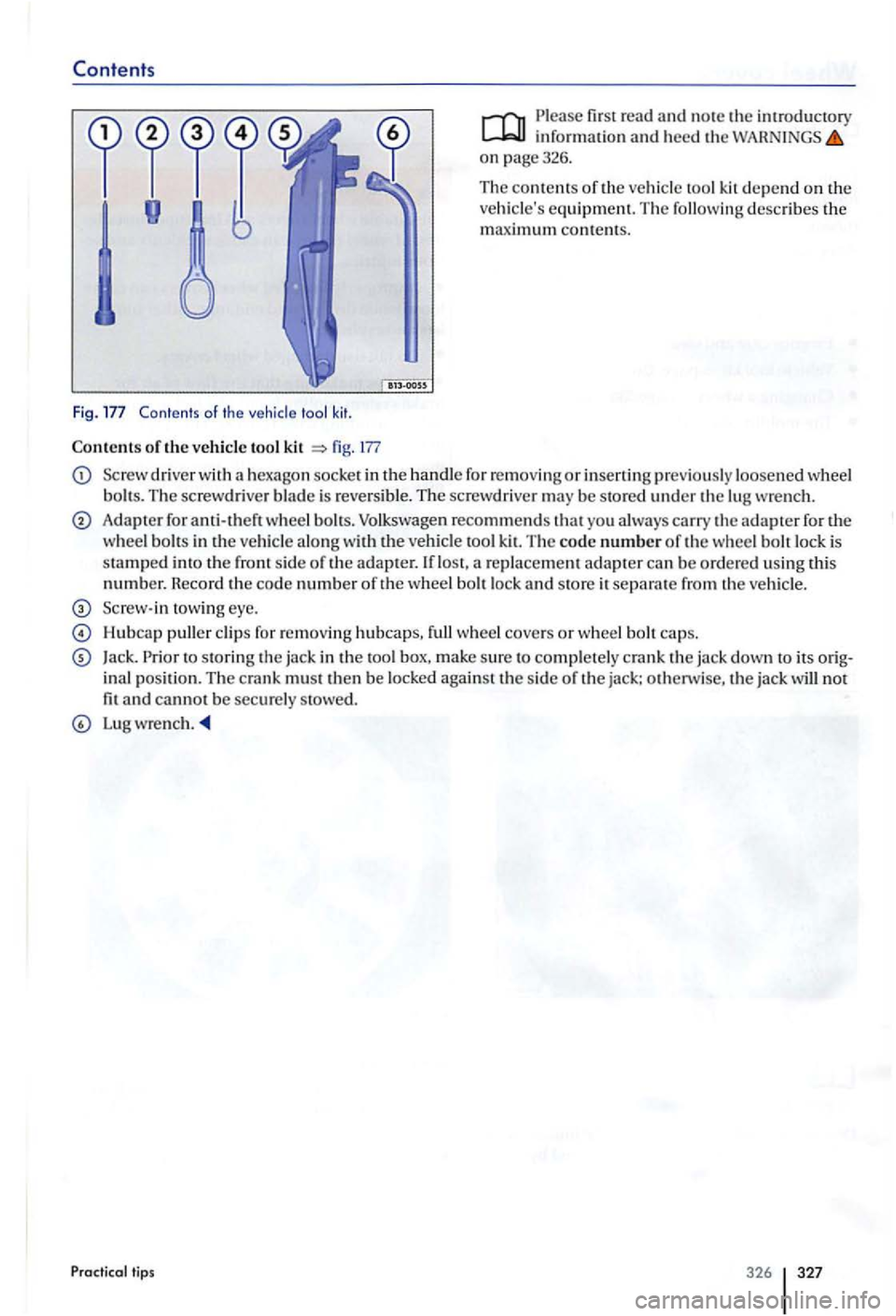
Fig . Contents of th e vehicle tool kit .
Con tents of th e vehicle tool kit fig. 177
Please first read and note the information and heed th e on page326.
T he
contents of th e ve hicl e tool kit d epend on the vehicle's equ ipment. The followin g describe s the maximum conte nt s.
Sc rewdri ver with a hexago n socke t in the handl e fo r r em ov ing or in se rting prev iou sly loosened w heel
bolt s. The screwdrive r blade is revers ible. The screw driver may be stored unde r th e lug wre nch.
Adapter for anti-theft wheel b olts. Volkswagen recom mends that yo u alw ays carry the adapte r fo r th e
w heel b olt s in the ve hicl e along w ith the veh icle tool The code number of the w heel bolt lock is
stamped th e sid e ofthe ad apter.
towing eye.
Hu bca p puller clip s for remov ing hubcaps, full wheel cover s or wheel b o lt caps.
Jack. Prior to stor in g th e jac k in the too l box, make s ure to co mpl ete ly crank the ja ck down to its ina l position. The cra nk mu st then b e locked against the sid e of the jack: oth erwise, the jack will not fit and cannot be sec urel y stowed.
Lug w rench .
Practica l tips
Page 326 of 541
hubcap against the rim until it
latch es.
To remove Twist hubcap to the le ft or righ t it loosens from the w heel page 328 , fig. 179.
cover
Fig.
firs t read and note the introductory information and heed the on page 328.
off the wheel cover
Take the lu g wre nch and wire dip out of the hicl e tool page 326.
caps
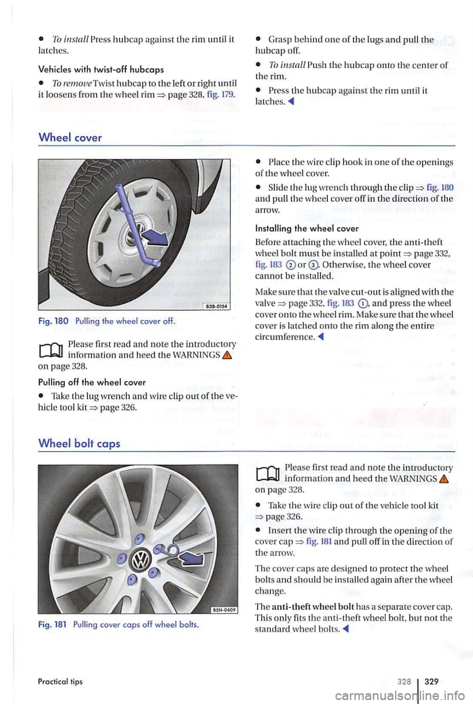
Fig . 181 Pullin g co ve r cop s off w he el b olts.
Practical lips
G rasp behind one of the lugs and pull the hubcap off.
To the hubcap onto th e center of th e rim.
th e hubcap against the rim until it
lat ch es.
th e w ire clip hook in one of the openings o f the w heel cover.
Slid e the lu g w rench through the fig. a nd pull th e wheel cove r off in the direction of the
arrow.
the wheel cover
B efor e attaching th e w heel cover, the anti-theft
w hee l bolt mus t be in stalled at p age332, fig. IB3 or Otherw ise, the wheel cover cannot be in stalled.
Ma ke s
ure that the valv e c ut-out is aligned w ith th e page 332. fig. 183 and press the wheel cover onto the wheel rim. Ma ke sure that th e w heel
cove r is latched onto the rim along the entire circumfere nce.
fir st read an d note the int rodu ctory informatio n and heed th e WARNINGS on page328.
Take the 326.
fig. 181 an d pull off in the dire ction of the arrow.
The
cove r caps are desig ned to protect th e w he el
b o lt s and should be i n stalled again after th e wheel
c h a nge.
Th e anti -th eft w h
eel bolt has a separate cover cap. Thi s only firs the anti-theft w heel bo lt , but not th e
s tan dard wheel bolt s.
328 329