clock VOLKSWAGEN GOLF PLUS 2012 User Guide
[x] Cancel search | Manufacturer: VOLKSWAGEN, Model Year: 2012, Model line: GOLF PLUS, Model: VOLKSWAGEN GOLF PLUS 2012Pages: 541, PDF Size: 98.86 MB
Page 332 of 541

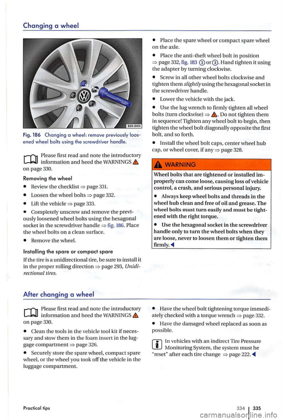
Fig. 186 Chang ing a wheel: remove previo usly ened wheel bolts using the screwdr iver handle .
first read and no te th e introduct ory inform ation and hee d the on page330.
R emov
ing the wheel
Revie w the pag e 331.
Loosen th e w heel page 332.
the page 333.
Complete ly unscrew and rem ove the ously loosened whee l bolt s using the hexago nal
soc ke t in the sc rew dri ver h andl e fig. 186. th e wheel bolts on a clea n surf ace .
Re m ove the w heel.
Installing the spare or compact spare
unidirectiona l tir e, b e sure to install it in the proper ro llin g pag e 293, tires.
After changing a
fir st read and note th e introductory info rm ation and hee d th e on page330.
Clea n th e tools in the vehicl e too l kit if sary and stow th em in th e foa m gage pag e 326.
Securely sto re th e spare whee l, compact spare
w heel, o r th e whee l yo u took off the vehicle in th e
lugga ge compartment.
Practical tips
the spare whee l o r compac t spare wheel on th e ax le.
th e a nti-th eft wheel bolt in position 332, fig. 183 Han d tigh ten it using the adapter b y turnin g clockw ise.
i n all other w hee l b olts clockw ise and tig ht en them slig/ u/yusin g th e hexago nal socket in
the screwdrive r handle.
Lower the ve hicl e with the jack .
the lug wre n ch to firml y tighten all wheel
bolt s (turn Do not tighten them in sequ en ce ! Tight en any wheel bolt to beg in, th en tighten th e wheel bo lt dia gonally opposite the first
b o lt, and so for th.
page 328.
Wh
eel bolts that a re tighte ned or installed p rope rly can come loo se, causing loss of vehicle
contro l,
Always keep whee l bolt s and threads in the
w hee l hub clean and free of oil and grease . The
wheel bolts mus t turn easil y and must be
the hexagona l socket in th e sc rewdriver
handl e o nly to turn th e w hee l bolt s when they are loo se, never to loosen th em or
Have th e w heel b o lt tightening to rqu e ately c hec ke d with a to rqu e wre nch page 332.
Have the dam aged whee l re p laced as soo n as
poss ible.
In ve hicles with indir ect T ir e Monitoring th e sys te m mu st b e after each tir e ch a nge
334 335
Page 355 of 541

If transmission has leake d out of th e missio n.
If there is o r n o oil in th e transmiss io n cause of damage to your ve hicl e, it mus t be moved
w ith th e dri ve wheels off th e ground.
If the front and rear w heels cannot t u rn.
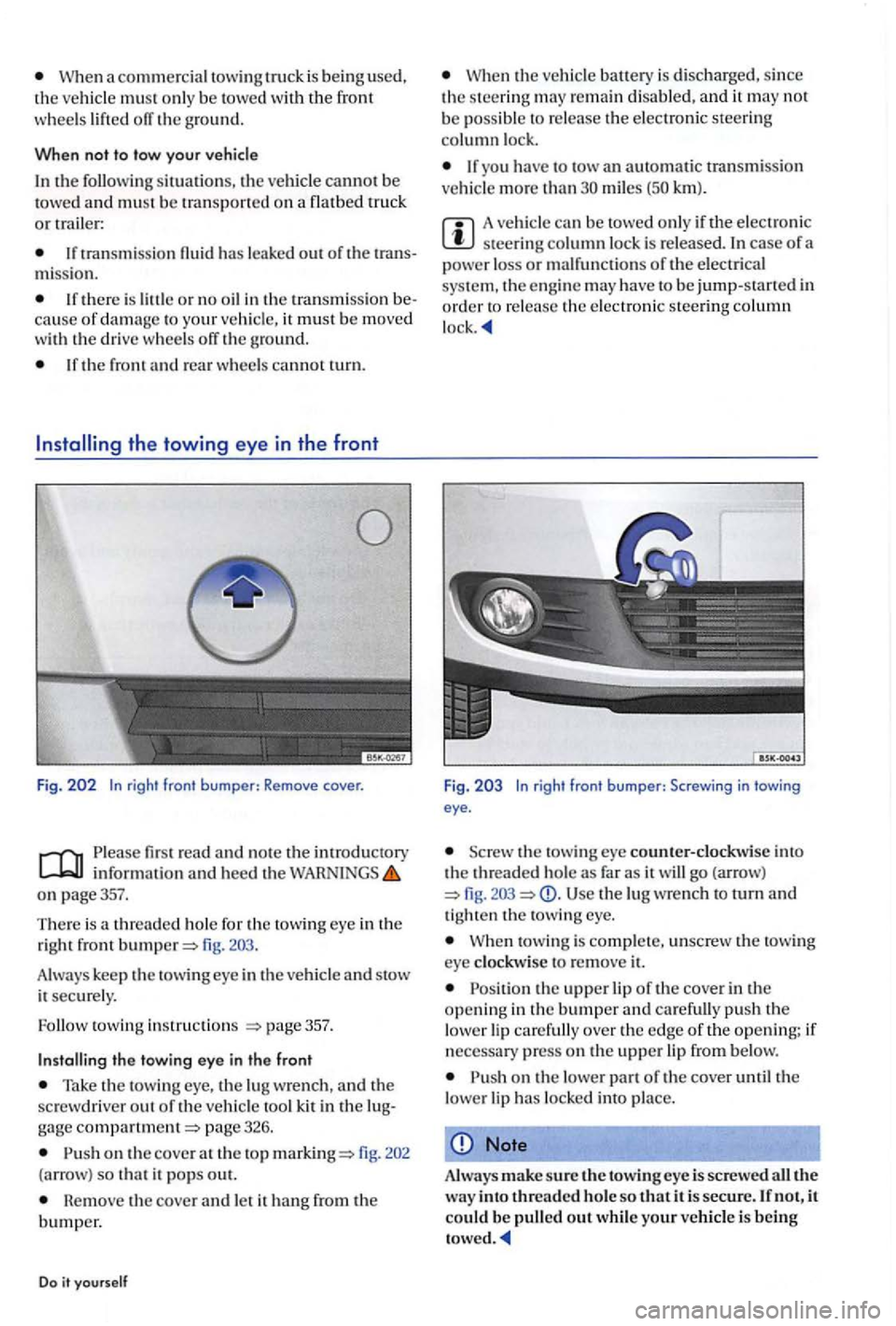
Fig . 202 In righ t front bumper : Remove cover.
read and note the introdu ctory information and heed the on page357.
T he re is a thread ed hole for
the tow ing eye in the
right front
Take the tow ing eye, the lu g wre nch, and the
sc rewdriver out o f the ve hicle too l kit in the page 326.
on the cove r at the top 202
(a rrow ) so that it pops out.
Remove the cover and let it hang from the bumper.
Do it yourself
the ve hicl e battery is disc harged, since the s teering re m ain disabled, and it may not be poss ibl e to release the elect ro ni c steerin g column lock.
If yo u have to tow an automatic tran smissio n
ve hicl e m ore th an miles km ).
A vehicle can be to we d onl y if the electro nic steerin g co lumn lock is released. In case of a
power loss or malfunc tions of the e lectrical
sys te m , th e e ngine may have to be jump-start ed in order to re lease the electroni c steerin g column
Fig . 2 0 3 In righ t front bumper: Screwing in t owi ng eye .
the tow ing eye counter-clock wise into the threaded ho le as far as it will go (arrow) Use the lug wrenc h to turn and tig ht en th e towing eye.
towing is compl e te, unscrew the towi ng eye cl ock wise to re m ove it.
on the lower part of the cover until the
lower lip has locke d into pla ce.
Note
Always make sure the towin g eye is screwe d all the w ay into threaded hole so that it is secure. If not, it could be pull ed out while your vehicle is being
Page 356 of 541

the towing eye in the rear
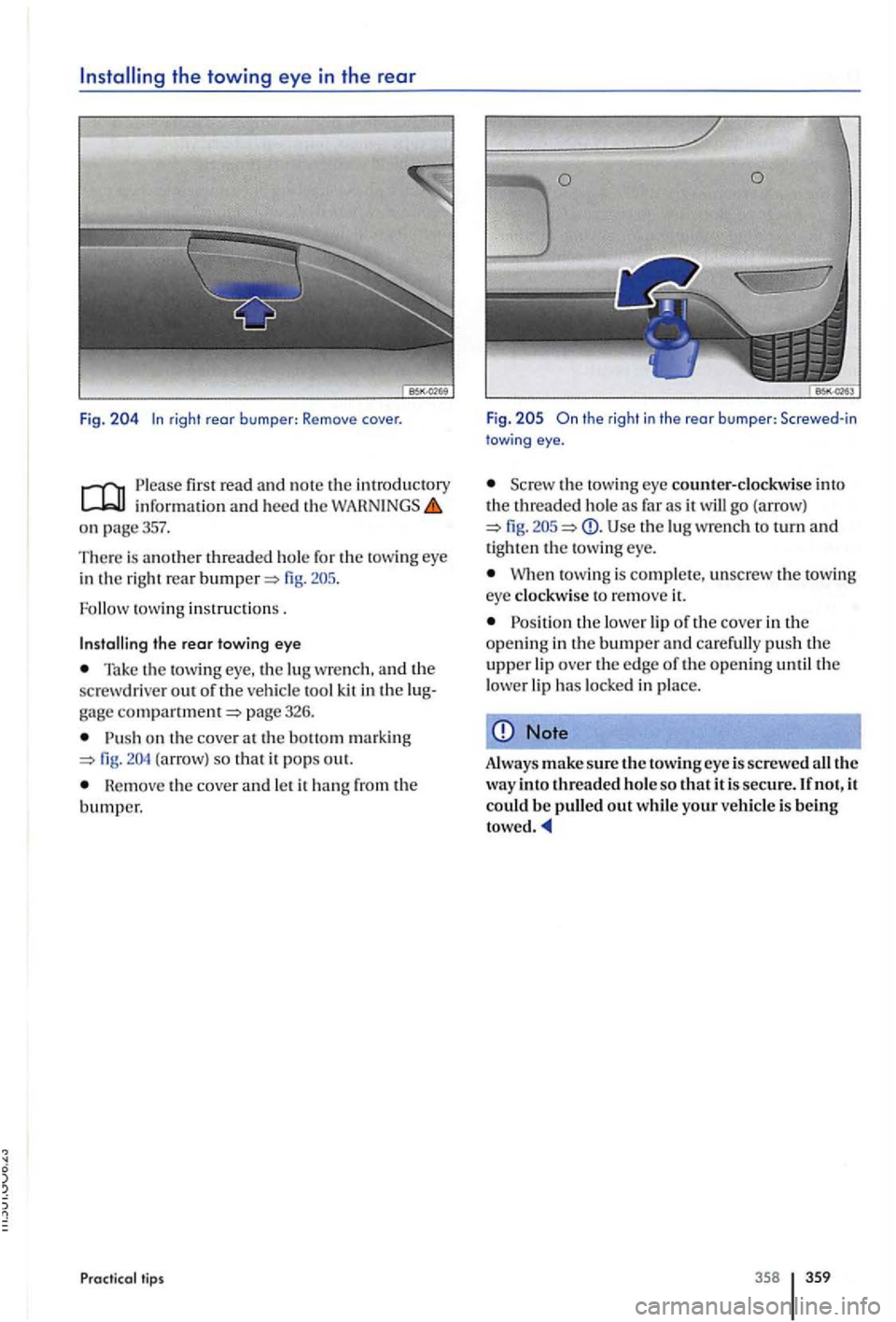
Fig. rig ht rear b umper: Remove cover.
P le ase first read and not e th e information and heed the
on page357.
The re is another threaded hole for the towing eye
in the right rear
tow ing instruction s .
the rear towing eye
Tak e the towing eye, the lu g w rench, and the
sc rewdrive r out of the veh icle tool kit in the
Pu sh on the cove r at the (arrow) so that it po ps out.
th e cover and le t it
tips
Fig .
the towing eye counter-clockwise into
th e threade d hol e as far as it will go (arrow) fig. Use th e lu g wrench to turn and tighten th e towin g eye.
W hen t owi ng is complet e, unscrew the towin g
eye clockwise to remove
Position th e lower lip of th e cover in th e
o penin g in the bumper and ca re full y push th e upper lip over the edge of th e opening until the
l ower lip has locke d in plac e.
Note
Always make sure the towing eye is screwe d all the way into threaded ho le so that it is secure . If n ot, it could be pulled out while your veh icle is being
358 359