tow VOLKSWAGEN GOLF SPORTWAGEN 2015 5G / 7.G Service Manual
[x] Cancel search | Manufacturer: VOLKSWAGEN, Model Year: 2015, Model line: GOLF SPORTWAGEN, Model: VOLKSWAGEN GOLF SPORTWAGEN 2015 5G / 7.GPages: 439, PDF Size: 6.16 MB
Page 417 of 439
6. Have all passengers exit and go to a safe place, such as behind a guard rail.
7. Block the diagonally opposite wheel with chocks or other suitable things.
8. If towing a trailer: Unhitch the trailer from the vehicle and park the trailer properly.
9. If the luggage compartment is loaded: Remove the luggage.
10. Raise and secure the luggage compartment floor.
11. If applicable: Remove the subwoofer ⇒ Removing the subwoofer.
12. Unscrew the fastening screw with washer counterclockwise and remove.
13. Take the spare or compact spare wheel and the vehicle tool kit out of the luggage compartment.
14. Take off the wheel covers ⇒ Wheel trim.
WARNING
Disregarding the safety-related checklist may lead to accidents and serious personal injuries.
x Always review and follow the checklist. Follow accepted safety practices and use common sense.
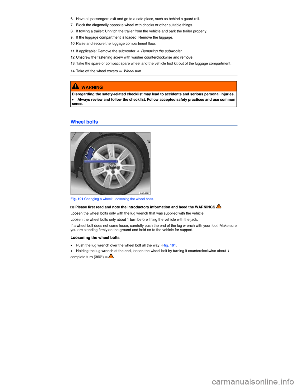
Wheel bolts
Fig. 191 Changing a wheel: Loosening the wheel bolts.
Page 421 of 439
The subwoofer, if equipped, is located under the luggage compartment floor and must be removed to access the spare wheel.
Removing the subwoofer
Follow these steps in the order listed:
1. Raise and secure the luggage compartment floor ⇒ Storage.
2. Unscrew the handwheel ⇒ fig. 194 (1) in a counterclockwise direction (arrow).
3. To release the connector, press and hold the center tab down with one hand (2).
4. With the other hand, grasp the connector on both sides, and carefully pull the connector out of the socket in the direction of the arrow (magnified view). Put the electric cable aside.
5. Remove the subwoofer carefully and place in a clean storage location.
Reinstalling the subwoofer
1. Reinstall the subwoofer carefully back into the recess. The tip of the arrow symbol “FRONT” on the subwoofer (3) must point toward the front of the vehicle
2. Insert the connector (2) into the socket until it clicks into place.
3. Turn the handwheel (1) clockwise to secure the subwoofer.
4. Carefully lower the luggage compartment floor back into place.
Changing a wheel
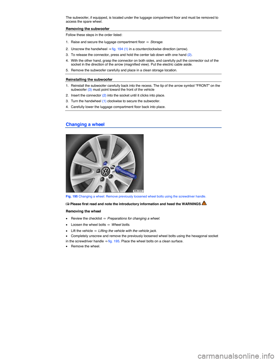
Fig. 195 Changing a wheel: Remove previously loosened wheel bolts using the screwdriver handle.
Page 425 of 439
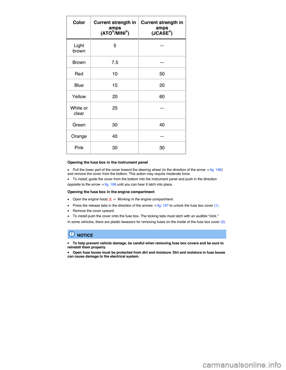
Color Current strength in
amps
(ATO®/MINI®)
Current strength in
amps
(JCASE®)
Light
brown
5 —
Brown 7.5 —
Red 10 50
Blue 15 20
Yellow 20 60
White or
clear
25 —
Green 30 40
Orange 40 —
Pink 30 30
Opening the fuse box in the instrument panel
x Pull the lower part of the cover toward the steering wheel (in the direction of the arrow ⇒ fig. 196) and remove the cover from the bottom. This action may require moderate force.
x To install, guide the cover from the bottom into the instrument panel and push in the direction
opposite to the arrow ⇒ fig. 196 until you can hear it latch into place.
Opening the fuse box in the engine compartment
x Open the engine hood
Page 431 of 439
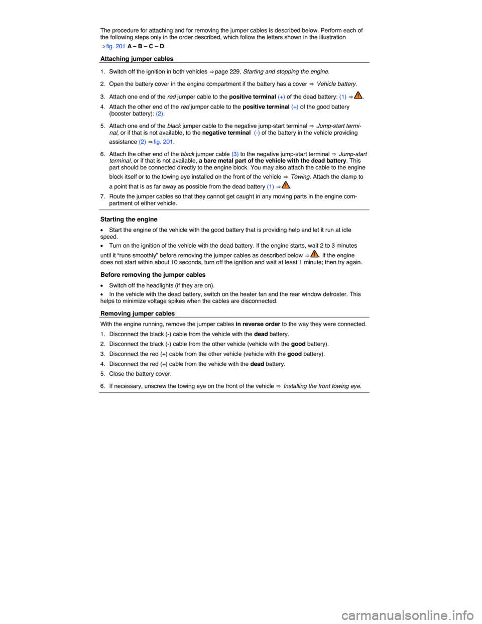
The procedure for attaching and for removing the jumper cables is described below. Perform each of the following steps only in the order described, which follow the letters shown in the illustration
⇒ fig. 201 A – B – C – D.
Attaching jumper cables
1. Switch off the ignition in both vehicles ⇒ page 229, Starting and stopping the engine.
2. Open the battery cover in the engine compartment if the battery has a cover ⇒ Vehicle battery.
3. Attach one end of the red jumper cable to the positive terminal (+) of the dead battery: (1) ⇒ .
4. Attach the other end of the red jumper cable to the positive terminal (+) of the good battery (booster battery): (2).
5. Attach one end of the black jumper cable to the negative jump-start terminal ⇒ Jump-start termi-nal, or if that is not available, to the negative terminal (-) of the battery in the vehicle providing
assistance (2) ⇒ fig. 201.
6. Attach the other end of the black jumper cable (3) to the negative jump-start terminal ⇒ Jump-start terminal, or if that is not available, a bare metal part of the vehicle with the dead battery. This part should be connected directly to the engine block. You may also attach the cable to the engine
block itself or to the towing eye installed on the front of the vehicle ⇒ Towing. Attach the clamp to
a point that is as far away as possible from the dead battery (1) ⇒ .
7. Route the jumper cables so that they cannot get caught in any moving parts in the engine com-partment of either vehicle.
Starting the engine
x Start the engine of the vehicle with the good battery that is providing help and let it run at idle speed.
x Turn on the ignition of the vehicle with the dead battery. If the engine starts, wait 2 to 3 minutes
until it “runs smoothly” before removing the jumper cables as described below ⇒ . If the engine does not start within about 10 seconds, turn off the ignition and wait at least 1 minute; then try again.
Before removing the jumper cables
x Switch off the headlights (if they are on).
x In the vehicle with the dead battery, switch on the heater fan and the rear window defroster. This helps to minimize voltage spikes when the cables are disconnected.
Removing jumper cables
With the engine running, remove the jumper cables in reverse order to the way they were connected.
1. Disconnect the black (-) cable from the vehicle with the dead battery.
2. Disconnect the black (-) cable from the other vehicle (vehicle with the good battery).
3. Disconnect the red (+) cable from the other vehicle (vehicle with the good battery).
4. Disconnect the red (+) cable from the vehicle with the dead battery.
5. Close the battery cover.
6. If necessary, unscrew the towing eye on the front of the vehicle ⇒ Installing the front towing eye.
Page 433 of 439
Towing
Page 434 of 439
WARNING
Towing a vehicle changes the way it handles and brakes. To help reduce the risk of an acci-dent and serious personal injury, note the following:
x The driver of the vehicle that is being towed:
– Since the brake booster also does not work when the engine is stopped, you will need to press harder on the brake pedal to slow down or stop. Always be alert so as not to rear-end the towing vehicle.
– Will have to use considerably more force to turn the steering wheel because the power steering is not working.
x The driver of the vehicle that is doing the towing:
– Must accelerate gradually and gently and avoid jerking movements.
– Must not brake hard or steer sharply.
– Must brake earlier and more gently than in normal driving.
NOTICE
x Be careful not to damage the paint when installing and removing the towing eye and the cover for the threaded hole behind the bumper.
x Unburned fuel can get into the catalytic converter during towing and damage it.
Towing on a commercial tow truck
Page 435 of 439
x If the front and rear wheels cannot turn.
x If the vehicle battery is dead (because the electronic steering column lock engages and cannot be released).
x If you have to tow an automatic transmission vehicle more than 30 miles (50 km).
WARNING
It is not safe for children or other persons to ride in a vehicle that is being towed.
x Never let children or anyone else remain in the vehicle while it is being towed.
NOTICE
The drive axle rotates while the vehicle is being towed with its rear wheels off the ground. This can damage the automatic transmission.
x Never tow automatic transmission vehicle with the rear wheels off the ground.
x Tow manual transmission vehicles with the rear wheels off the ground only if it is certain that no transmission fluid can leak out.
Tips on towing
Page 436 of 439
x When a commercial tow truck is being used, the vehicle must only be towed with the front wheels lifted off the ground.
When not to tow your vehicle
In the following situations, the vehicle cannot be towed and must be transported on a flatbed truck or trailer:
x If transmission fluid has leaked out of the transmission.
x If there is little or no oil in the transmission because of damage to your vehicle, it must be moved with the drive wheels off the ground.
x If the front and rear wheels cannot turn.
x When the vehicle battery is dead, because the steering may remain disabled and it may not be possible to release the electronic steering column lock.
x If you have to tow an automatic transmission vehicle more than 30 miles (50 km).
x If the steering or the wheel clearance might be impaired, for example, after an accident.
Towing other vehicles
x Obey all legal requirements
x Read and heed all towing information in the owner's manual for the other vehicle.
A vehicle can be towed only if the electronic steering column lock is released. In case of a power loss or malfunctions of the electrical system, the engine may have to be jump-started in order to re-lease the electronic steering column lock.
Installing the front towing eye
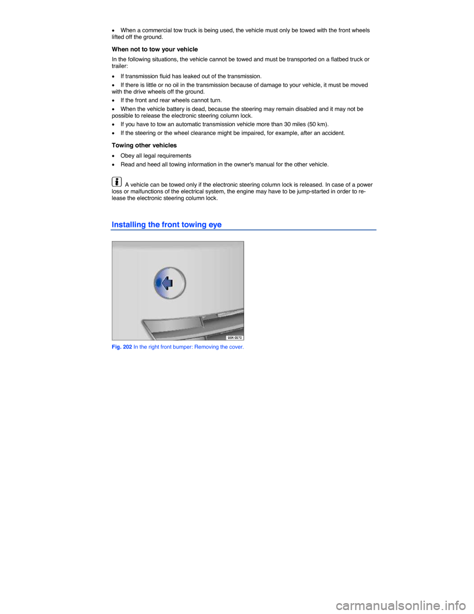
Fig. 202 In the right front bumper: Removing the cover.
Page 437 of 439
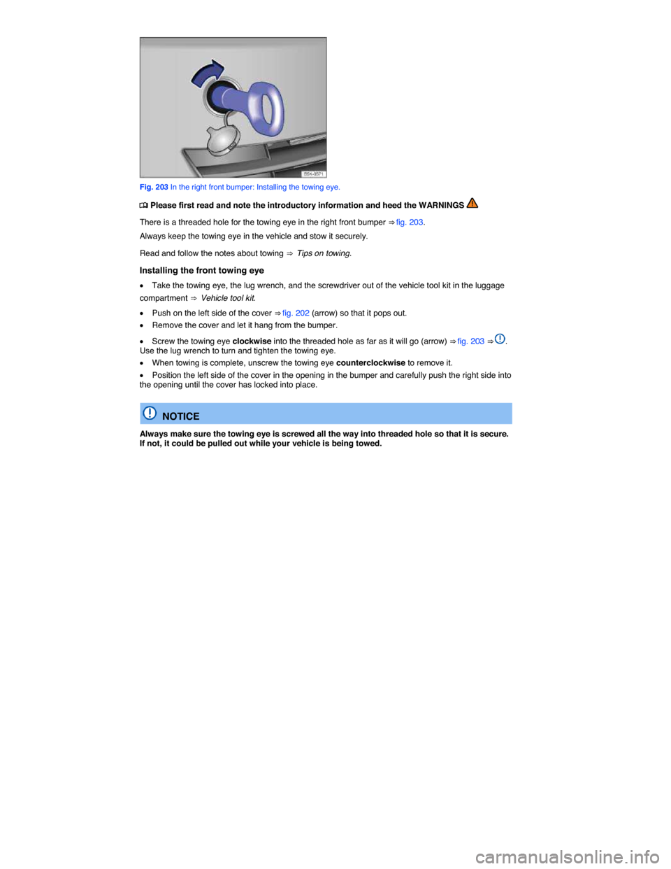
Fig. 203 In the right front bumper: Installing the towing eye.
Page 438 of 439
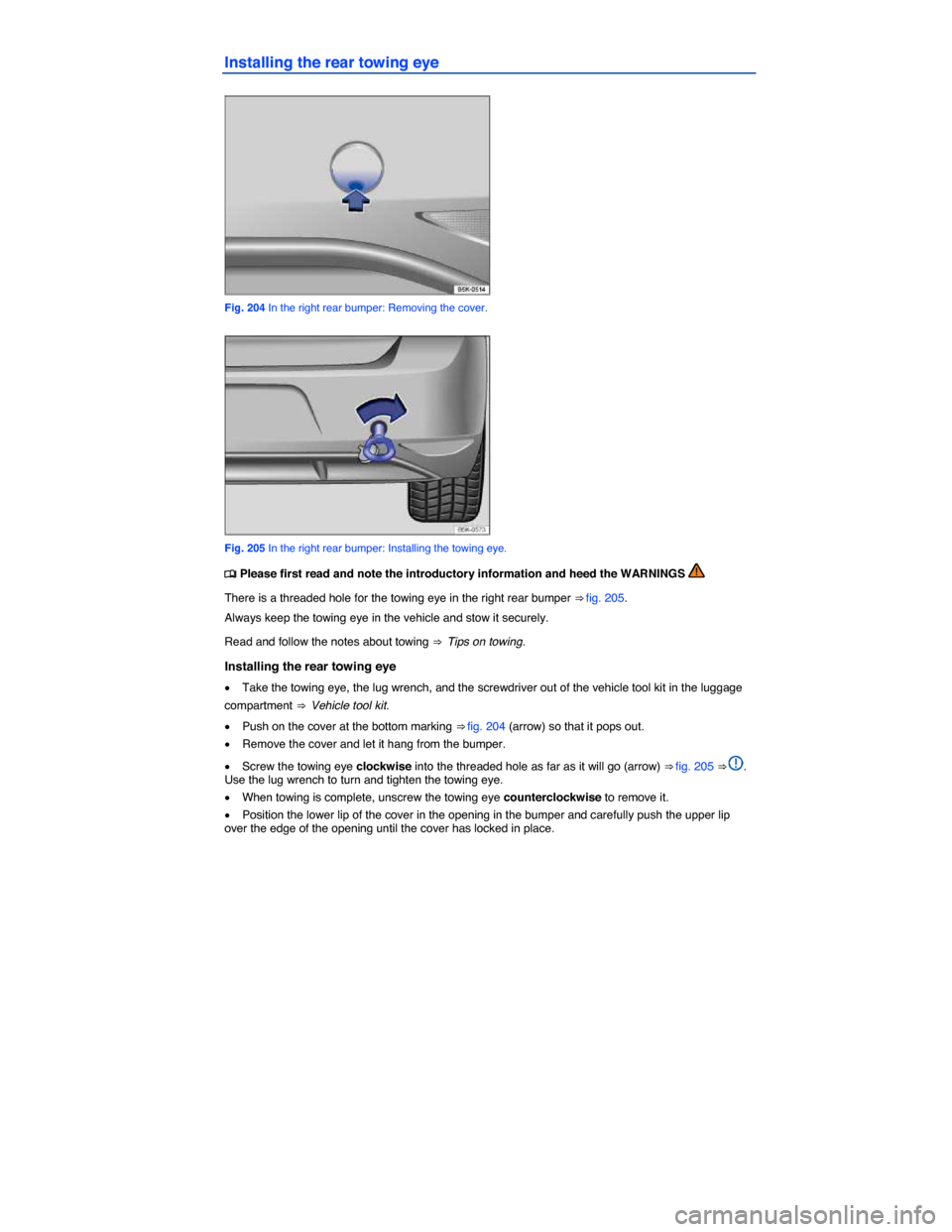
Installing the rear towing eye
Fig. 204 In the right rear bumper: Removing the cover.
Fig. 205 In the right rear bumper: Installing the towing eye.