light VOLKSWAGEN PASSAT 1995 B3, B4 / 3.G Service User Guide
[x] Cancel search | Manufacturer: VOLKSWAGEN, Model Year: 1995, Model line: PASSAT, Model: VOLKSWAGEN PASSAT 1995 B3, B4 / 3.GPages: 369, PDF Size: 12.33 MB
Page 303 of 369
Downloaded from www.Manualslib.com manuals search engine 48-33
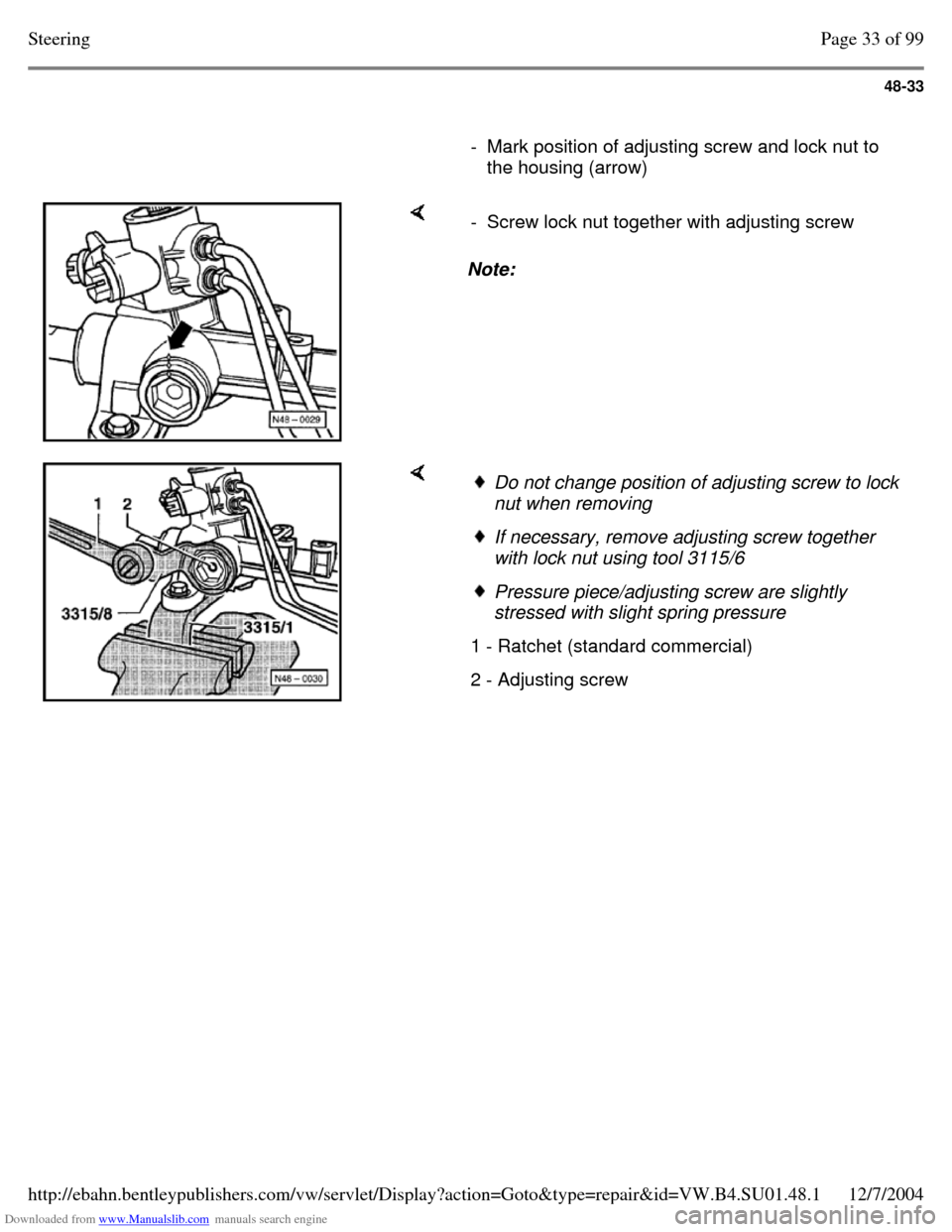
- Mark position of adjusting screw and lock nut to
the housing (arrow) Note: - Screw lock nut together with adjusting screw Do not change position of adjusting screw to lock
nut when removing If necessary, remove adjusting screw together
with lock nut using tool 3115/6 Pressure piece/adjusting screw are slightly
stressed with slight spring pressure
1 - Ratchet (standard commercial) 2 - Adjusting screw Page 33 of 99Steering12/7/2004http://ebahn.bentleypublishers.com/vw/servlet/Display?action=Goto&type=repair&id=VW.B4.SU01.48.1
Page 310 of 369
Downloaded from www.Manualslib.com manuals search engine 48-40
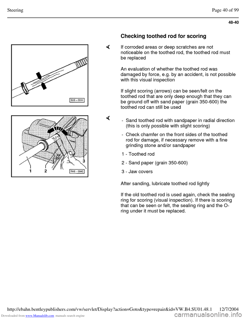
Checking toothed rod for scoring If corroded areas or deep scratches are not
noticeable on the toothed rod, the toothed rod must
be replaced
An evaluation of whether the toothed rod was
damaged by force, e.g. by an accident, is not possible
with this visual inspection
If slight scoring (arrows) can be seen/felt on the
toothed rod that are only deep enough that they can
be ground off with sand paper (grain 350-600) the
toothed rod can still be used After sanding, lubricate toothed rod lightly
If the old toothed rod is used again, check the sealing
ring for scoring (visual inspection). If there is scoring
that can be seen or felt, the sealing ring and the O-
ring under it must be replaced. - Sand toothed rod with sandpaper in radial direction (this is only possible with slight scoring)
- Check chamfer on the front sides of the toothed
rod for damage, if necessary remove with a fine
grinding stone and/or sandpaper
1 - Toothed rod 2 - Sand paper (grain 350-600) 3 - Jaw covers Page 40 of 99Steering12/7/2004http://ebahn.bentleypublishers.com/vw/servlet/Display?action=Goto&type=repair&id=VW.B4.SU01.48.1
Page 311 of 369
Downloaded from www.Manualslib.com manuals search engine 48-41
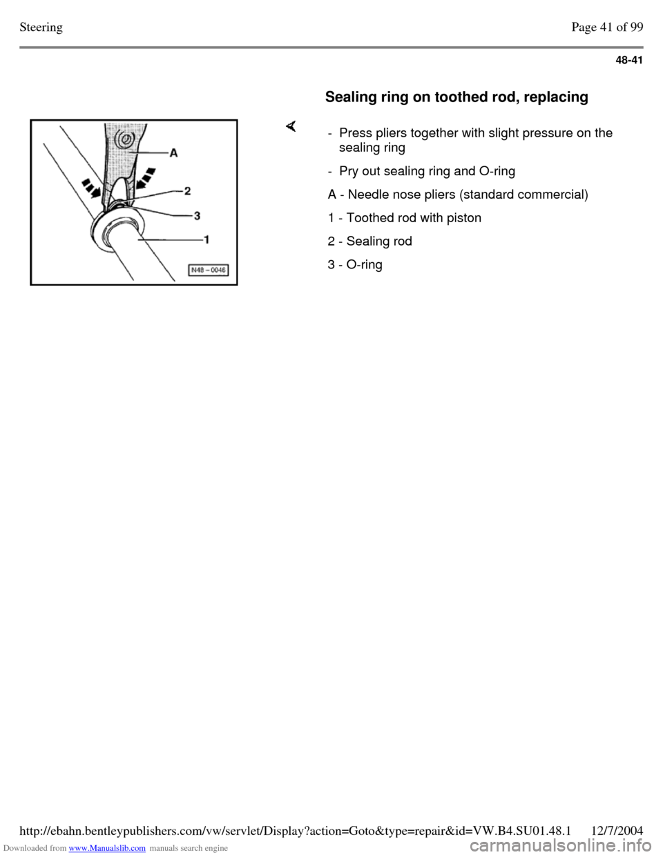
Sealing ring on toothed rod, replacing - Press pliers together with slight pressure on the
sealing ring
- Pry out sealing ring and O-ring A - Needle nose pliers (standard commercial) 1 - Toothed rod with piston 2 - Sealing rod 3 - O-ring Page 41 of 99Steering12/7/2004http://ebahn.bentleypublishers.com/vw/servlet/Display?action=Goto&type=repair&id=VW.B4.SU01.48.1
Page 323 of 369
Downloaded from www.Manualslib.com manuals search engine 48-53
Needle run-out max. 0.10 mm
If needle run-out is greater than 0.10 mm, screw
pressure piece slightly into housing
If the needle run-out is less than 0.10 mm, screw
pressure piece slightly out of housing
- Tighten lock nut
- Check needle run-out again, if necessary repeat
adjustment
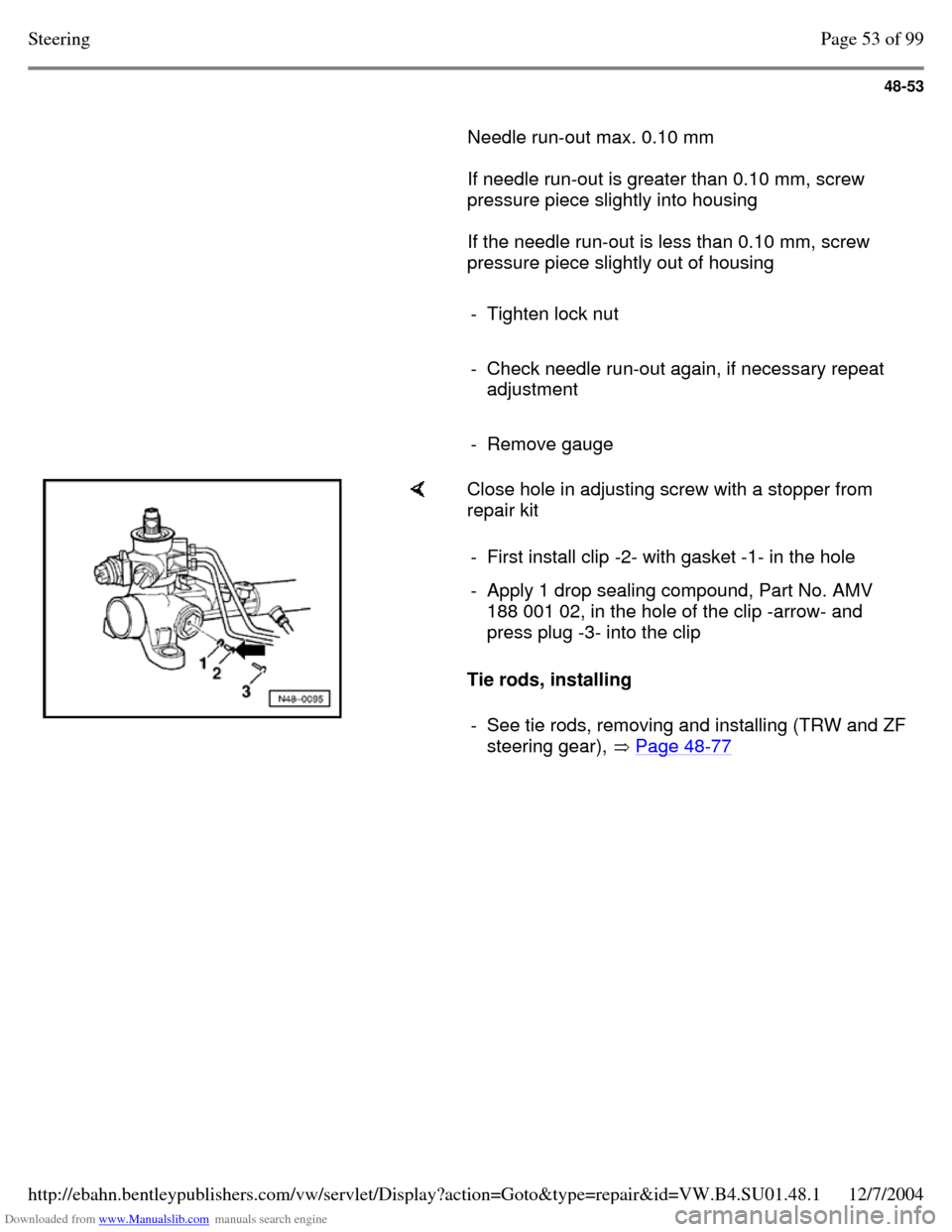
- Remove gauge Close hole in adjusting screw with a stopper from
repair kit
Tie rods, installing - First install clip -2- with gasket -1- in the hole - Apply 1 drop sealing compound, Part No. AMV
188 001 02, in the hole of the clip -arrow- and
press plug -3- into the clip
- See tie rods, removing and installing (TRW and ZF steering gear), Page 48-77 Page 53 of 99Steering12/7/2004http://ebahn.bentleypublishers.com/vw/servlet/Display?action=Goto&type=repair&id=VW.B4.SU01.48.1
Page 332 of 369
Downloaded from www.Manualslib.com manuals search engine 48-62
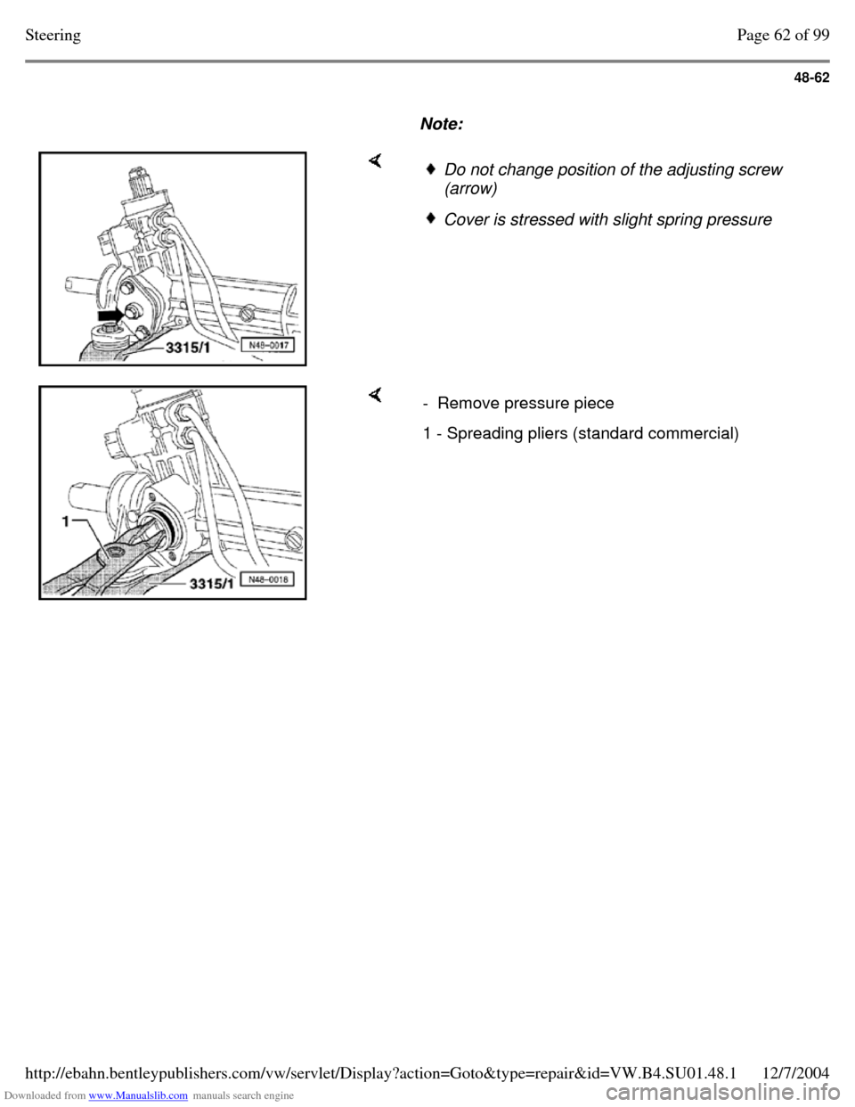
Note: Do not change position of the adjusting screw
(arrow) Cover is stressed with slight spring pressure - Remove pressure piece 1 - Spreading pliers (standard commercial) Page 62 of 99Steering12/7/2004http://ebahn.bentleypublishers.com/vw/servlet/Display?action=Goto&type=repair&id=VW.B4.SU01.48.1
Page 339 of 369
Downloaded from www.Manualslib.com manuals search engine 48-69
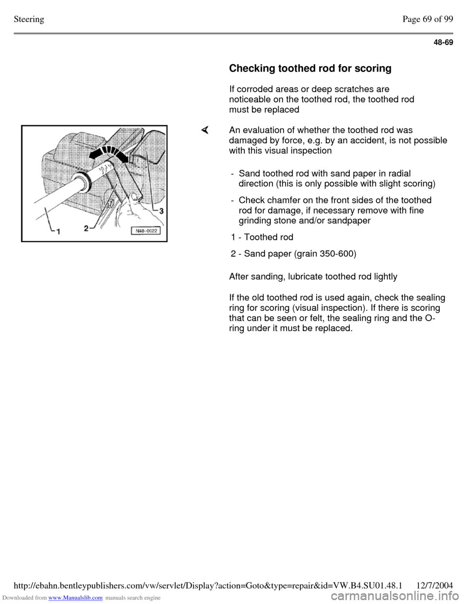
Checking toothed rod for scoring
If corroded areas or deep scratches are
noticeable on the toothed rod, the toothed rod
must be replaced An evaluation of whether the toothed rod was
damaged by force, e.g. by an accident, is not possible
with this visual inspection
After sanding, lubricate toothed rod lightly
If the old toothed rod is used again, check the sealing
ring for scoring (visual inspection). If there is scoring
that can be seen or felt, the sealing ring and the O-
ring under it must be replaced. - Sand toothed rod with sand paper in radial
direction (this is only possible with slight scoring)
- Check chamfer on the front sides of the toothed
rod for damage, if necessary remove with fine
grinding stone and/or sandpaper
1 - Toothed rod 2 - Sand paper (grain 350-600) Page 69 of 99Steering12/7/2004http://ebahn.bentleypublishers.com/vw/servlet/Display?action=Goto&type=repair&id=VW.B4.SU01.48.1
Page 340 of 369
Downloaded from www.Manualslib.com manuals search engine 48-70
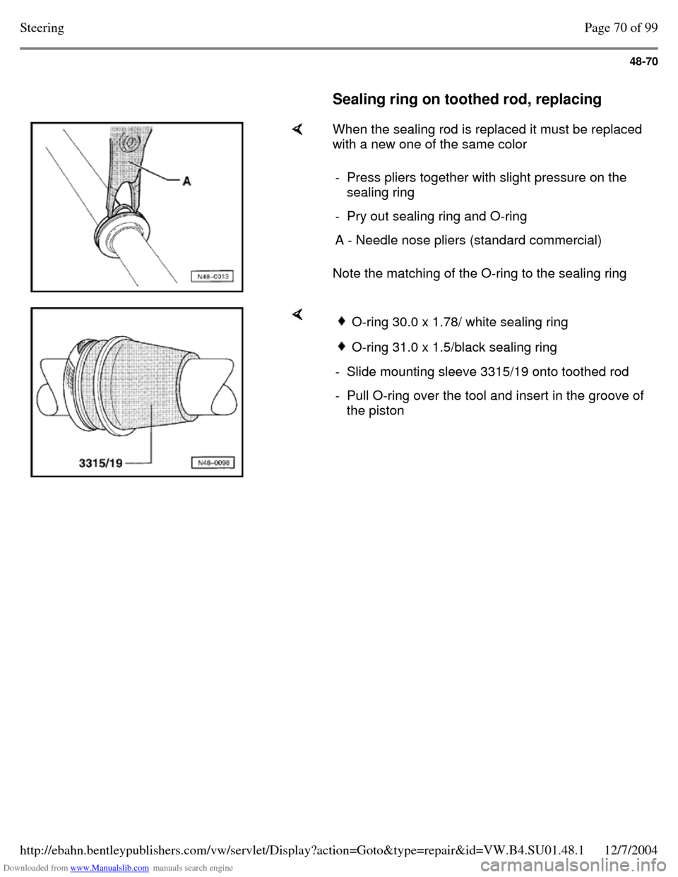
Sealing ring on toothed rod, replacing When the sealing rod is replaced it must be replaced
with a new one of the same color
Note the matching of the O-ring to the sealing ring - Press pliers together with slight pressure on the
sealing ring
- Pry out sealing ring and O-ring A - Needle nose pliers (standard commercial) O-ring 30.0 x 1.78/ white sealing ring O-ring 31.0 x 1.5/black sealing ring - Slide mounting sleeve 3315/19 onto toothed rod - Pull O-ring over the tool and insert in the groove of
the piston Page 70 of 99Steering12/7/2004http://ebahn.bentleypublishers.com/vw/servlet/Display?action=Goto&type=repair&id=VW.B4.SU01.48.1
Page 341 of 369
Downloaded from www.Manualslib.com manuals search engine 48-71
Power steering gear, assembling
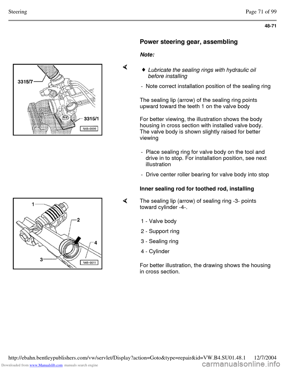
Note: The sealing lip (arrow) of the sealing ring points
upward toward the teeth 1 on the valve body
For better viewing, the illustration shows the body
housing in cross section with installed valve body.
The valve body is shown slightly raised for better
viewing
Inner sealing rod for toothed rod, installing Lubricate the sealing rings with hydraulic oil
before installing
- Note correct installation position of the sealing ring - Place sealing ring for valve body on the tool and
drive in to stop. For installation position, see next
illustration
- Drive center roller bearing for valve body into stop The sealing lip (arrow) of sealing ring -3- points
toward cylinder -4-.
For better illustration, the drawing shows the housing
in cross section. 1 - Valve body 2 - Support ring 3 - Sealing ring 4 - Cylinder Page 71 of 99Steering12/7/2004http://ebahn.bentleypublishers.com/vw/servlet/Display?action=Goto&type=repair&id=VW.B4.SU01.48.1