Power steering VOLKSWAGEN PASSAT 1995 B3, B4 / 3.G Service Owner's Manual
[x] Cancel search | Manufacturer: VOLKSWAGEN, Model Year: 1995, Model line: PASSAT, Model: VOLKSWAGEN PASSAT 1995 B3, B4 / 3.GPages: 369, PDF Size: 12.33 MB
Page 331 of 369
Downloaded from www.Manualslib.com manuals search engine 48-61
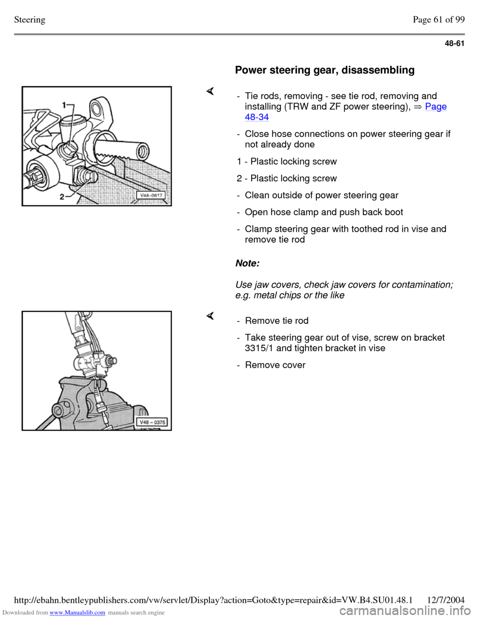
Power steering gear, disassembling Note:
Use jaw covers, check jaw covers for contamination;
e.g. metal chips or the like - Tie rods, removing - see tie rod, removing and
installing (TRW and ZF power steering), Page 48-34 - Close hose connections on power steering gear if
not already done
1 - Plastic locking screw 2 - Plastic locking screw - Clean outside of power steering gear - Open hose clamp and push back boot - Clamp steering gear with toothed rod in vise and
remove tie rod - Remove tie rod - Take steering gear out of vise, screw on bracket
3315/1 and tighten bracket in vise
- Remove cover Page 61 of 99Steering12/7/2004http://ebahn.bentleypublishers.com/vw/servlet/Display?action=Goto&type=repair&id=VW.B4.SU01.48.1
Page 341 of 369
Downloaded from www.Manualslib.com manuals search engine 48-71
Power steering gear, assembling
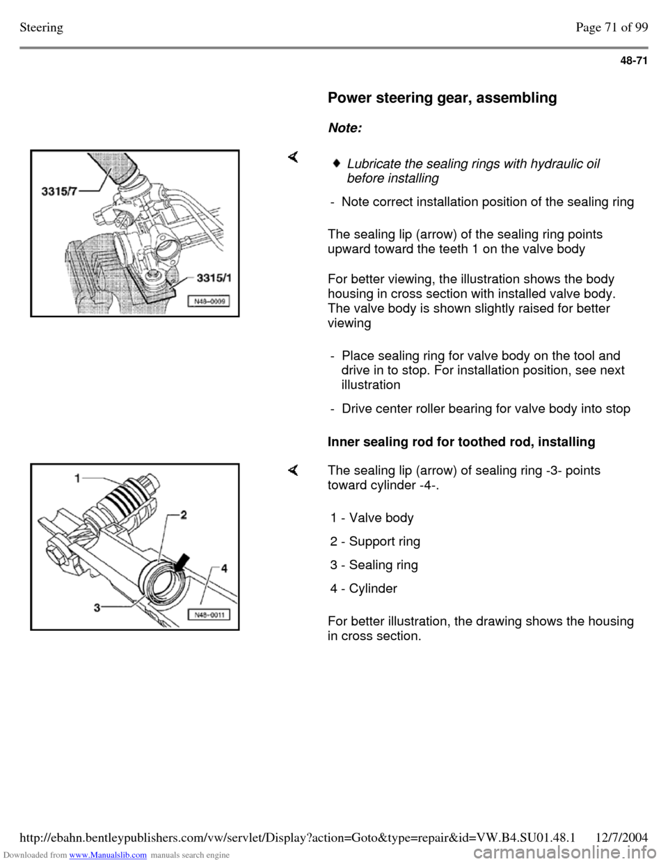
Note: The sealing lip (arrow) of the sealing ring points
upward toward the teeth 1 on the valve body
For better viewing, the illustration shows the body
housing in cross section with installed valve body.
The valve body is shown slightly raised for better
viewing
Inner sealing rod for toothed rod, installing Lubricate the sealing rings with hydraulic oil
before installing
- Note correct installation position of the sealing ring - Place sealing ring for valve body on the tool and
drive in to stop. For installation position, see next
illustration
- Drive center roller bearing for valve body into stop The sealing lip (arrow) of sealing ring -3- points
toward cylinder -4-.
For better illustration, the drawing shows the housing
in cross section. 1 - Valve body 2 - Support ring 3 - Sealing ring 4 - Cylinder Page 71 of 99Steering12/7/2004http://ebahn.bentleypublishers.com/vw/servlet/Display?action=Goto&type=repair&id=VW.B4.SU01.48.1
Page 347 of 369
Downloaded from www.Manualslib.com manuals search engine 48-77
Tie rods, removing and installing (power
steering gear - TRW and ZF)
Note:
Observe how tie rods are threaded into power
steering gear:
- Tie rods not secured with locking fluid
- Tie rods secured with locking fluid When exchanging secured version tie rods use
locking fluid D6 when installing.
Removing
The tie rods can only be removed/installed with
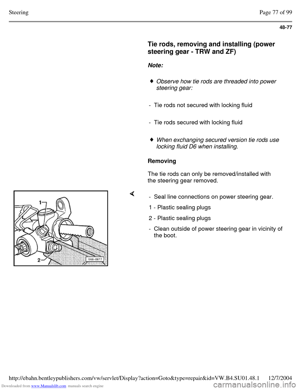
the steering gear removed. - Seal line connections on power steering gear. 1 - Plastic sealing plugs 2 - Plastic sealing plugs - Clean outside of power steering gear in vicinity of
the boot. Page 77 of 99Steering12/7/2004http://ebahn.bentleypublishers.com/vw/servlet/Display?action=Goto&type=repair&id=VW.B4.SU01.48.1
Page 351 of 369
Downloaded from www.Manualslib.com manuals search engine 48-81
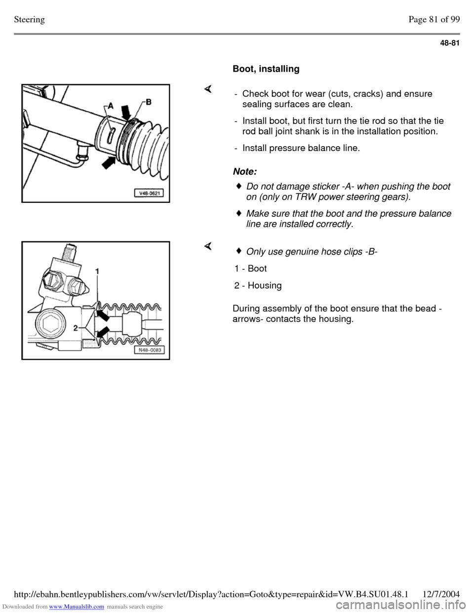
Boot, installing Note: - Check boot for wear (cuts, cracks) and ensure
sealing surfaces are clean.
- Install boot, but first turn the tie rod so that the tie
rod ball joint shank is in the installation position.
- Install pressure balance line. Do not damage sticker -A- when pushing the boot
on (only on TRW power steering gears). Make sure that the boot and the pressure balance
line are installed correctly. During assembly of the boot ensure that the bead -
arrows- contacts the housing. Only use genuine hose clips -B- 1 - Boot 2 - Housing Page 81 of 99Steering12/7/2004http://ebahn.bentleypublishers.com/vw/servlet/Display?action=Goto&type=repair&id=VW.B4.SU01.48.1
Page 358 of 369
Downloaded from www.Manualslib.com manuals search engine 48-88
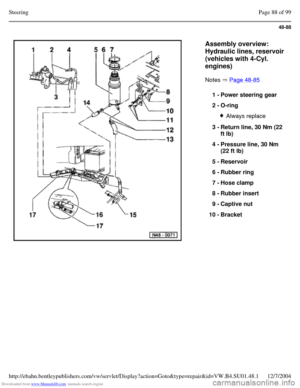
Assembly overview:
Hydraulic lines, reservoir
(vehicles with 4-Cyl.
engines)
Notes Page 48-85 1 - Power steering gear
2 - O-ring Always replace 3 - Return line, 30 Nm (22
ft lb)
4 - Pressure line, 30 Nm
(22 ft lb)
5 - Reservoir
6 - Rubber ring
7 - Hose clamp
8 - Rubber insert
9 - Captive nut
10 - Bracket Page 88 of 99Steering12/7/2004http://ebahn.bentleypublishers.com/vw/servlet/Display?action=Goto&type=repair&id=VW.B4.SU01.48.1
Page 360 of 369
Downloaded from www.Manualslib.com manuals search engine 48-90
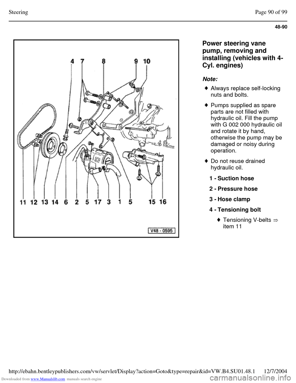
Power steering vane
pump, removing and
installing (vehicles with 4-
Cyl. engines)
Note: Always replace self-locking
nuts and bolts. Pumps supplied as spare
parts are not filled with
hydraulic oil. Fill the pump with G 002 000 hydraulic oil and rotate it by hand, otherwise the pump may be damaged or noisy during
operation. Do not reuse drained
hydraulic oil.
1 - Suction hose
2 - Pressure hose
3 - Hose clamp
4 - Tensioning bolt Tensioning V-belts
item 11 Page 90 of 99Steering12/7/2004http://ebahn.bentleypublishers.com/vw/servlet/Display?action=Goto&type=repair&id=VW.B4.SU01.48.1
Page 365 of 369
Downloaded from www.Manualslib.com manuals search engine 48-95
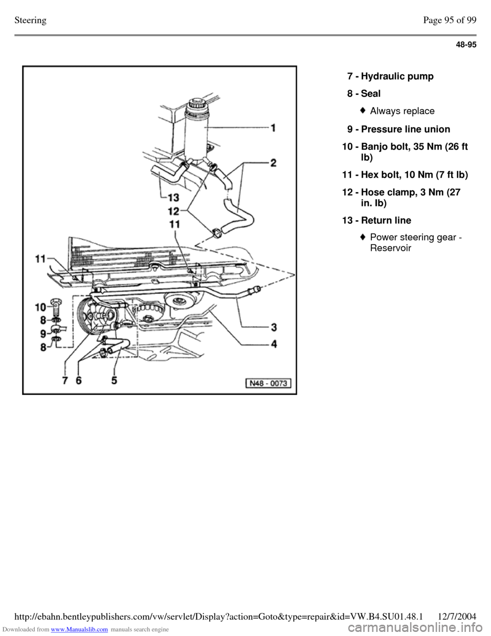
7 - Hydraulic pump
8 - Seal Always replace 9 - Pressure line union
10 - Banjo bolt, 35 Nm (26 ft lb)
11 - Hex bolt, 10 Nm (7 ft lb) 12 - Hose clamp, 3 Nm (27
in. Ib)
13 - Return line Power steering gear -
Reservoir Page 95 of 99Steering12/7/2004http://ebahn.bentleypublishers.com/vw/servlet/Display?action=Goto&type=repair&id=VW.B4.SU01.48.1
Page 367 of 369
![VOLKSWAGEN PASSAT 1995 B3, B4 / 3.G Service Owners Manual Downloaded from www.Manualslib.com manuals search engine 48-97
Power steering vane
pump, removing and
installing (vehicles with
VR6 engine]
Note: Always replace seals. Do not reuse drained VOLKSWAGEN PASSAT 1995 B3, B4 / 3.G Service Owners Manual Downloaded from www.Manualslib.com manuals search engine 48-97
Power steering vane
pump, removing and
installing (vehicles with
VR6 engine]
Note: Always replace seals. Do not reuse drained](/img/18/7419/w960_7419-366.png)
Downloaded from www.Manualslib.com manuals search engine 48-97
Power steering vane
pump, removing and
installing (vehicles with
VR6 engine]
Note: Always replace seals. Do not reuse drained
hydraulic oil. Pumps supplied as spare
parts are not filled with oil.
Fill the pump with G 002
000 hydraulic oil and rotate
it by hand, otherwise the
pump may be damaged or
noisy during operation.
1 - Suction hose A cooling line is installed between vane pump suction hose
and reservoir
2 - Hose clamp Page 97 of 99Steering12/7/2004http://ebahn.bentleypublishers.com/vw/servlet/Display?action=Goto&type=repair&id=VW.B4.SU01.48.1