brake VOLKSWAGEN PASSAT 1995 B3, B4 / 3.G Service Owner's Guide
[x] Cancel search | Manufacturer: VOLKSWAGEN, Model Year: 1995, Model line: PASSAT, Model: VOLKSWAGEN PASSAT 1995 B3, B4 / 3.GPages: 369, PDF Size: 12.33 MB
Page 157 of 369
Downloaded from www.Manualslib.com manuals search engine 42-61
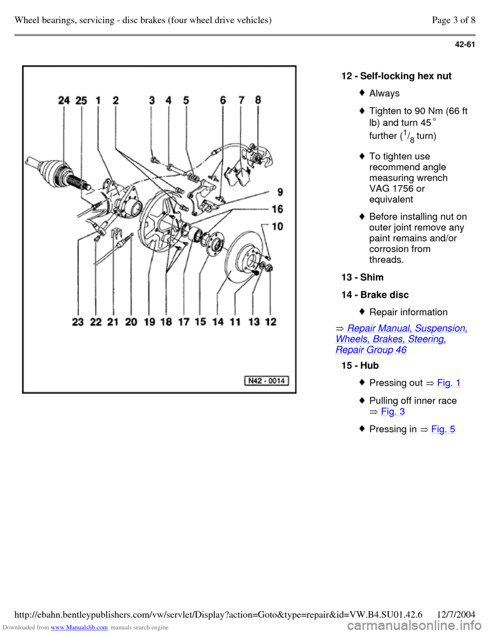
Repair Manual, Suspension, Wheels, Brakes, Steering, Repair Group 46 12 - Self-locking hex nut Always Tighten to 90 Nm (66 ft lb) and turn 45
further (1
/
8 turn) To tighten use
recommend angle
measuring wrench
VAG 1756 or
equivalent Before installing nut on outer joint remove any
paint remains and/or
corrosion from
threads.
13 - Shim
14 - Brake disc Repair information 15 - Hub Pressing out Fig. 1 Pulling off inner race
Fig. 3 Pressing in Fig. 5 Page 3 of 8Wheel bearings, servicing - disc brakes (four wheel drive vehicles)12/7/2004http://ebahn.bentleypublishers.com/vw/servlet/Display?action=Goto&type=repair&id=VW.B4.SU01.42.6
Page 158 of 369
Downloaded from www.Manualslib.com manuals search engine 42-62
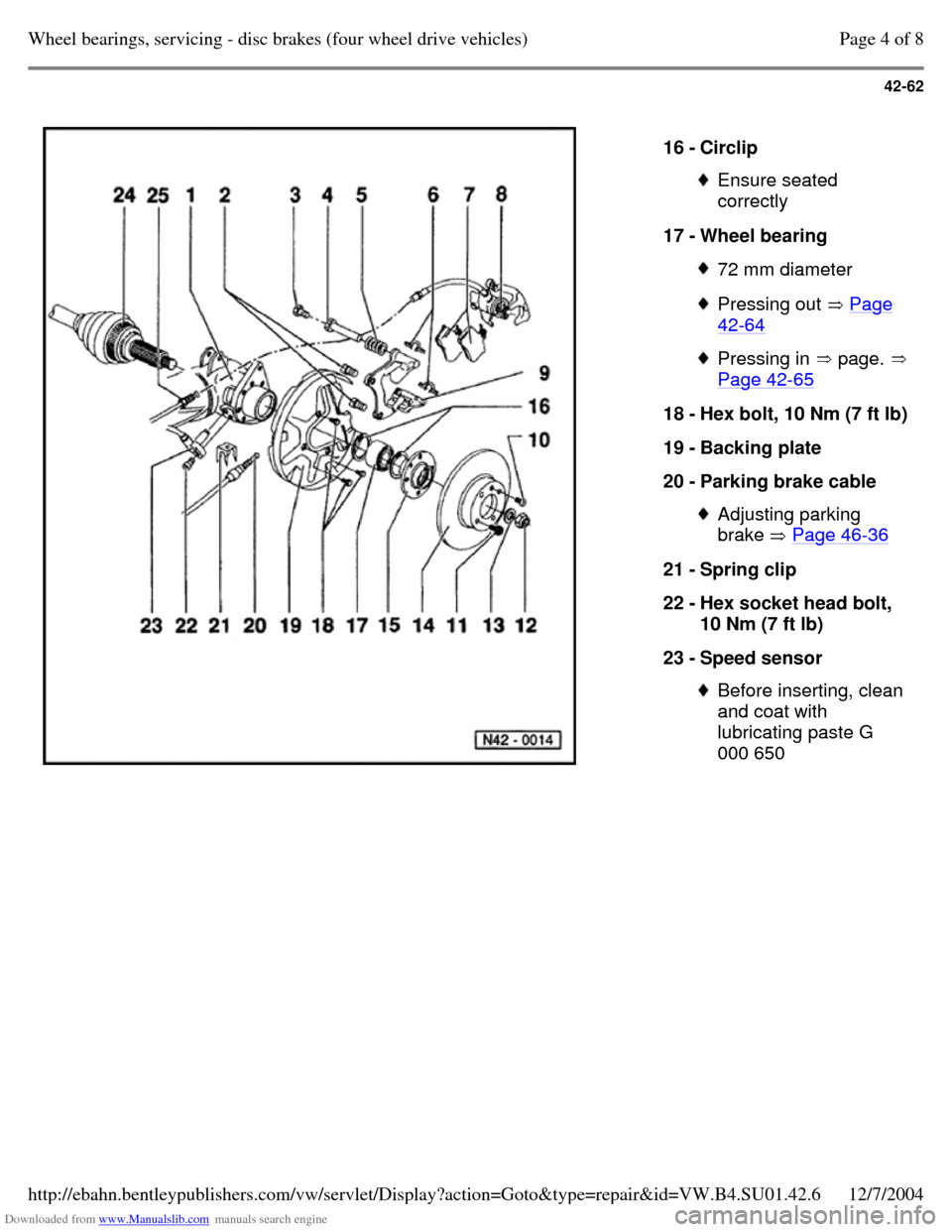
16 - Circlip Ensure seated
correctly
17 - Wheel bearing 72 mm diameter Pressing out Page 42-64 Pressing in page. Page 42-65 18 - Hex bolt, 10 Nm (7 ft lb) 19 - Backing plate
20 - Parking brake cable Adjusting parking
brake Page 46-36 21 - Spring clip
22 - Hex socket head bolt,
10 Nm (7 ft lb)
23 - Speed sensor Before inserting, clean
and coat with
lubricating paste G
000 650 Page 4 of 8Wheel bearings, servicing - disc brakes (four wheel drive vehicles)12/7/2004http://ebahn.bentleypublishers.com/vw/servlet/Display?action=Goto&type=repair&id=VW.B4.SU01.42.6
Page 159 of 369
Downloaded from www.Manualslib.com manuals search engine 42-63
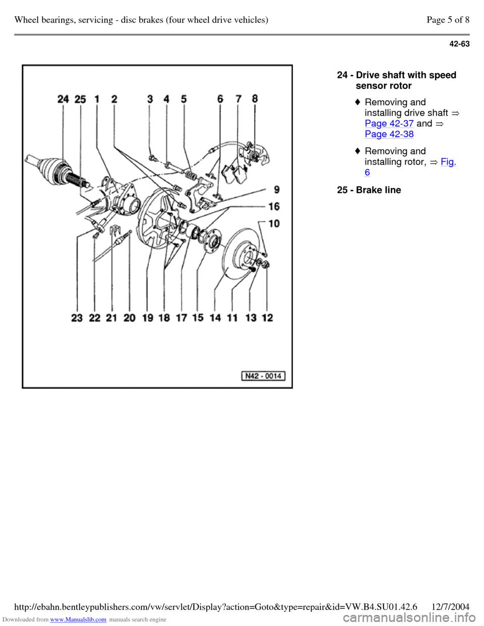
24 - Drive shaft with speed
sensor rotor Removing and
installing drive shaft
Page 42-37 and
Page 42-38 Removing and
installing rotor, Fig. 6 25 - Brake line Page 5 of 8Wheel bearings, servicing - disc brakes (four wheel drive vehicles)12/7/2004http://ebahn.bentleypublishers.com/vw/servlet/Display?action=Goto&type=repair&id=VW.B4.SU01.42.6
Page 160 of 369
Downloaded from www.Manualslib.com manuals search engine 42-64
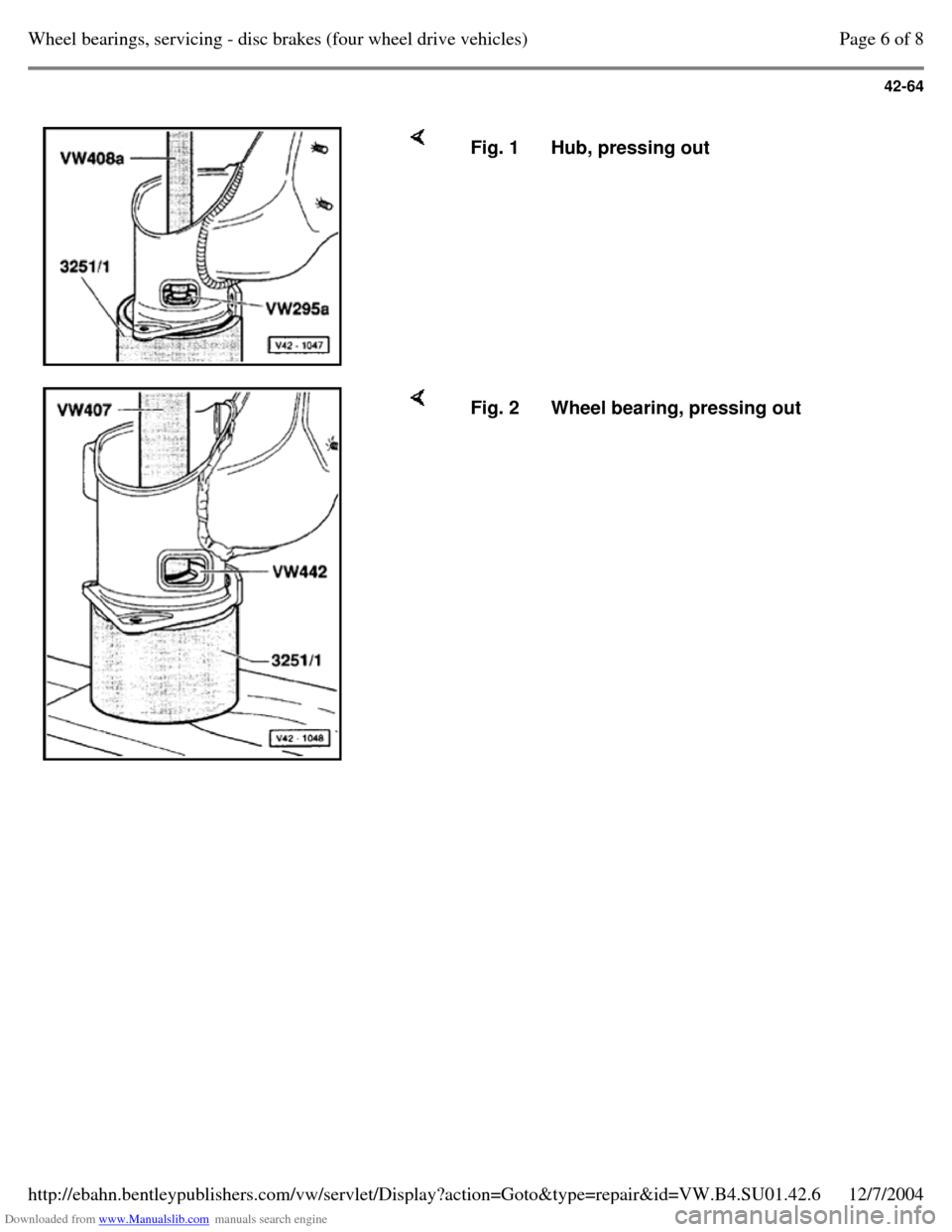
Fig. 1 Hub, pressing out Fig. 2 Wheel bearing, pressing out Page 6 of 8Wheel bearings, servicing - disc brakes (four wheel drive vehicles)12/7/2004http://ebahn.bentleypublishers.com/vw/servlet/Display?action=Goto&type=repair&id=VW.B4.SU01.42.6
Page 161 of 369

Downloaded from www.Manualslib.com manuals search engine 42-65
Note:
Only use puller with leg clamp e.g. Kukko 204-2
(commercial type). Fig. 3 Inner race, pulling off of hub Note:
First install lower circlip. Fig. 4 Wheel bearing, pressing in Page 7 of 8Wheel bearings, servicing - disc brakes (four wheel drive vehicles)12/7/2004http://ebahn.bentleypublishers.com/vw/servlet/Display?action=Goto&type=repair&id=VW.B4.SU01.42.6
Page 162 of 369
Downloaded from www.Manualslib.com manuals search engine 42-66
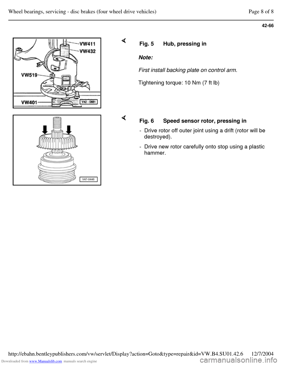
Note:
First install backing plate on control arm.
Tightening torque: 10 Nm (7 ft lb) Fig. 5 Hub, pressing in Fig. 6 Speed sensor rotor, pressing in - Drive rotor off outer joint using a drift (rotor will be
destroyed).
- Drive new rotor carefully onto stop using a plastic
hammer. Page 8 of 8Wheel bearings, servicing - disc brakes (four wheel drive vehicles)12/7/2004http://ebahn.bentleypublishers.com/vw/servlet/Display?action=Goto&type=repair&id=VW.B4.SU01.42.6
Page 167 of 369
Downloaded from www.Manualslib.com manuals search engine 44-5
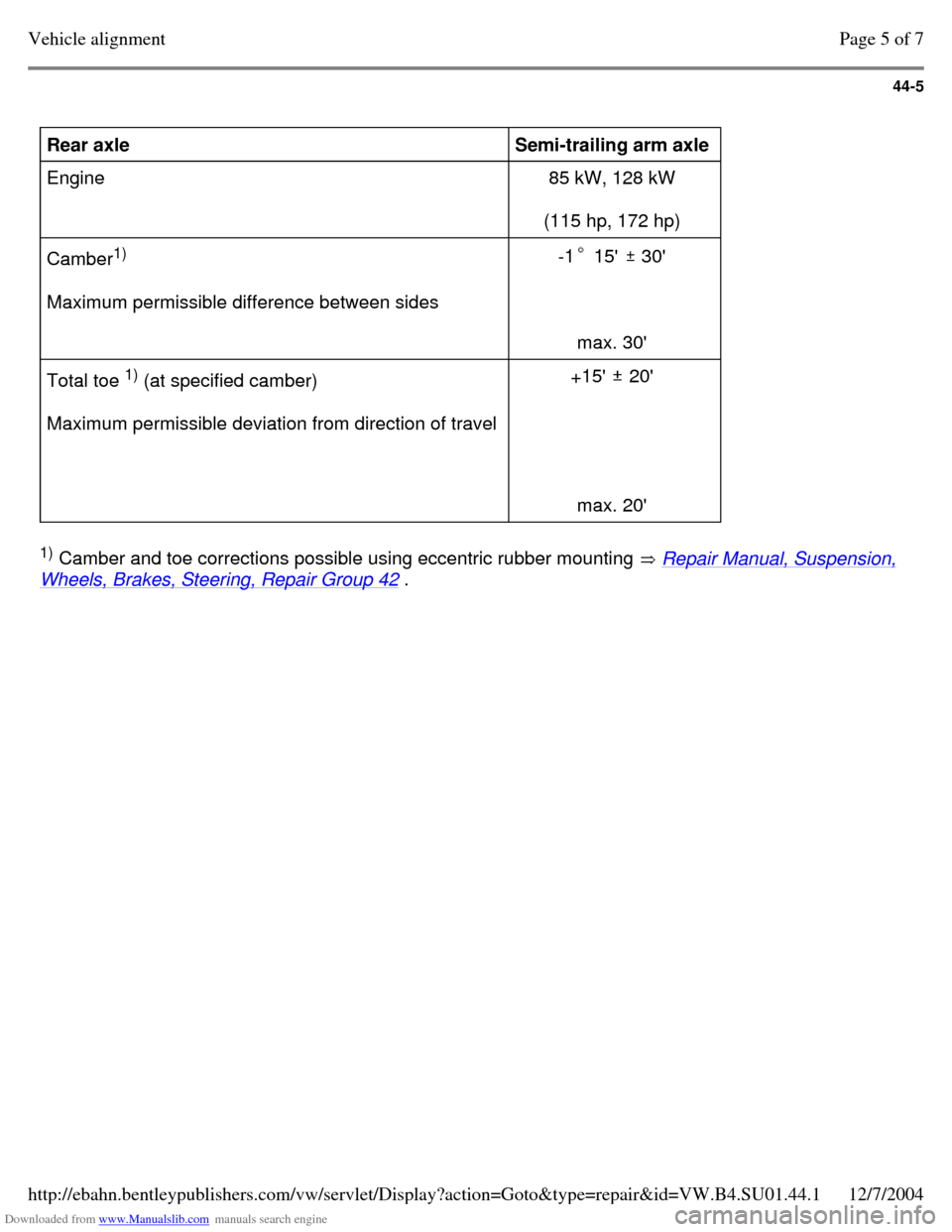
Rear axle
Semi-trailing arm axle
Engine 85 kW, 128 kW
(115 hp, 172 hp)
Camber1)
Maximum permissible difference between sides -1 15' 30'
max. 30' Total toe 1)
(at specified camber)
Maximum permissible deviation from direction of travel +15' 20'
max. 20' 1)
Camber and toe corrections possible using eccentric rubber mounting Repair Manual, Suspension, Wheels, Brakes, Steering, Repair Group 42 . Page 5 of 7Vehicle alignment12/7/2004http://ebahn.bentleypublishers.com/vw/servlet/Display?action=Goto&type=repair&id=VW.B4.SU01.44.1
Page 170 of 369

Downloaded from www.Manualslib.com manuals search engine 45-1
Anti-locking Brake System
(ABS) and Anti-locking Brake
System with Electronic
Differential Lock (ABS/EDL)
Teves 04
The ABS, ABS/EDL brake system is divided
diagonally. The servo-assist is effected
pneumatically, by the vacuum brake servo unit.
Located between the brake master cylinder and
the vacuum servo unit is a mounting bracket for
the hydraulic unit with pump.
The hydraulic unit together with pump, supplies
only the anti-locking brake system (ABS) or anti-
locking brake system and traction control system
(ABS/EDL).
Malfunctions on the ABS, ABS/EDL systems do
not influence the brake system and servo. The
vehicle can be driven without the ABS, ABS/EDL
functions operating. Page 1 of 5Anti-locking Brake System (ABS) and Anti-locking Brake System with Electronic Differential Lock (A...12/7/2004http://ebahn.bentleypublishers.com/vw/servlet/Display?action=Goto&type=repair&id=VW.B4.SU01.45.1
Page 171 of 369
Downloaded from www.Manualslib.com manuals search engine 45-2
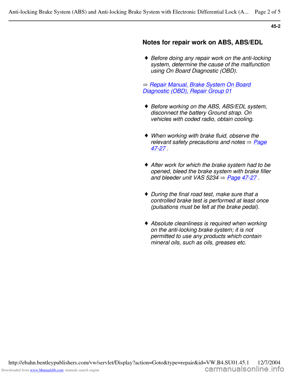
Notes for repair work on ABS, ABS/EDL
Before doing any repair work on the anti-locking system, determine the cause of the malfunction
using On Board Diagnostic (OBD).
Repair Manual, Brake System On Board Diagnostic (OBD), Repair Group 01 Before working on the ABS, ABS/EDL system,
disconnect the battery Ground strap. On
vehicles with coded radio, obtain cooling.
When working with brake fluid, observe the
relevant safety precautions and notes Page 47-27 . After work for which the brake system had to be opened, bleed the brake system with brake filler and bleeder unit VAS 5234 Page 47-27 . During the final road test, make sure that a
controlled brake test is performed at least once
(pulsations must be felt at the brake pedal).
Absolute cleanliness is required when working
on the anti-locking brake system; it is not
permitted to use any products which contain
mineral oils, such as oils, greases etc. Page 2 of 5Anti-locking Brake System (ABS) and Anti-locking Brake System with Electronic Differential Lock (A...12/7/2004http://ebahn.bentleypublishers.com/vw/servlet/Display?action=Goto&type=repair&id=VW.B4.SU01.45.1
Page 172 of 369
Downloaded from www.Manualslib.com manuals search engine 45-3
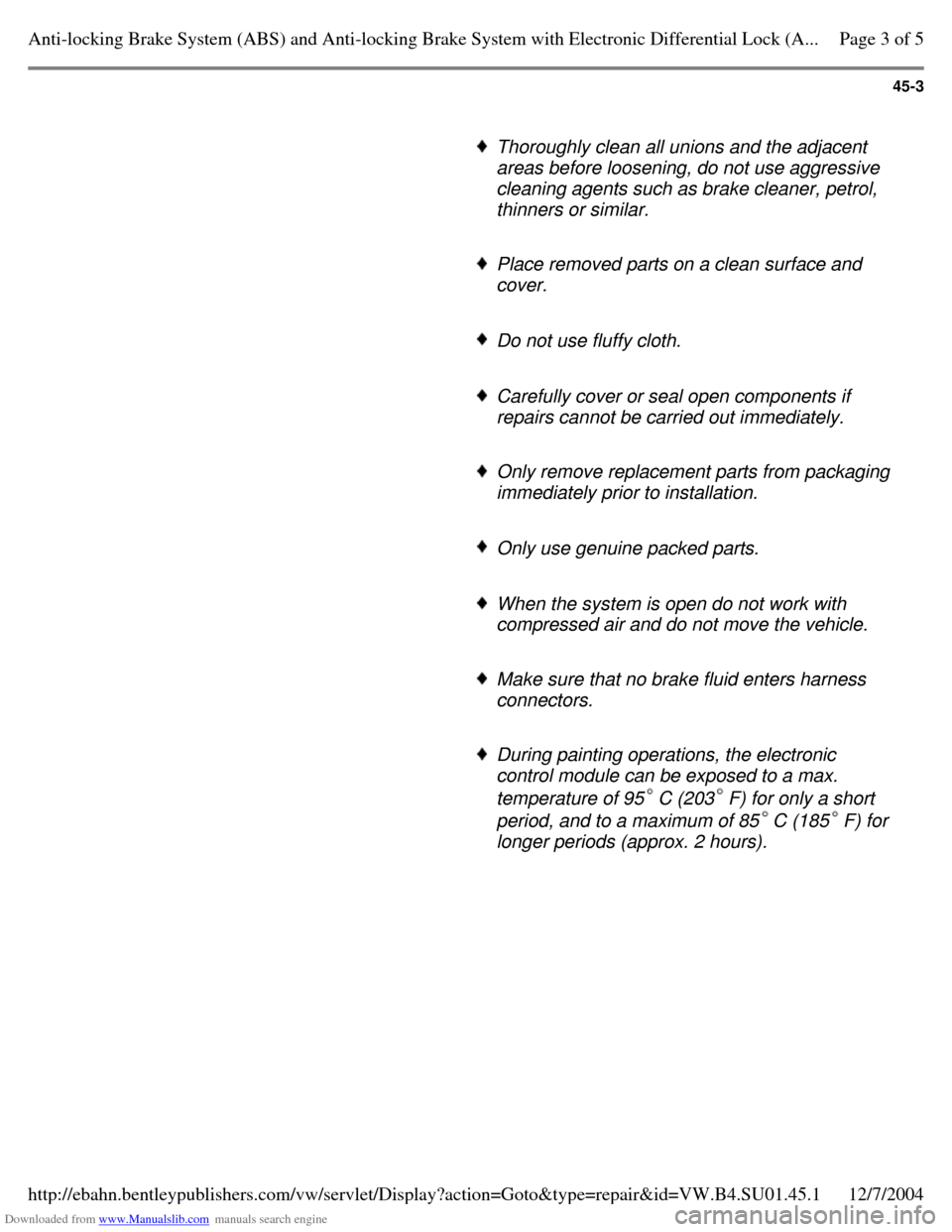
Thoroughly clean all unions and the adjacent
areas before loosening, do not use aggressive
cleaning agents such as brake cleaner, petrol,
thinners or similar.
Place removed parts on a clean surface and
cover.
Do not use fluffy cloth. Carefully cover or seal open components if
repairs cannot be carried out immediately.
Only remove replacement parts from packaging
immediately prior to installation.
Only use genuine packed parts. When the system is open do not work with
compressed air and do not move the vehicle.
Make sure that no brake fluid enters harness
connectors.
During painting operations, the electronic
control module can be exposed to a max.
temperature of 95C (203F) for only a short
period, and to a maximum of 85C (185F) for
longer periods (approx. 2 hours). Page 3 of 5Anti-locking Brake System (ABS) and Anti-locking Brake System with Electronic Differential Lock (A...12/7/2004http://ebahn.bentleypublishers.com/vw/servlet/Display?action=Goto&type=repair&id=VW.B4.SU01.45.1