VOLKSWAGEN PASSAT 1995 B3, B4 / 3.G Service Repair Manual
PASSAT 1995 B3, B4 / 3.G
VOLKSWAGEN
VOLKSWAGEN
https://www.carmanualsonline.info/img/18/7419/w960_7419-0.png
VOLKSWAGEN PASSAT 1995 B3, B4 / 3.G Service Repair Manual
Page 51 of 369
Downloaded from www.Manualslib.com manuals search engine 40-37
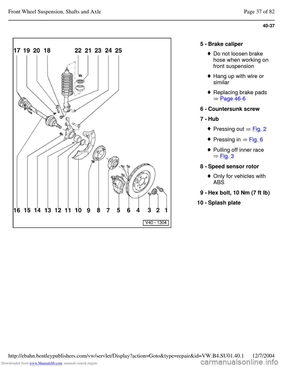
5 - Brake caliper Do not loosen brake
hose when working on
front suspension Hang up with wire or
similar Replacing brake pads
Page 46-6 6 - Countersunk screw
7 - Hub Pressing out Fig. 2 Pressing in Fig. 6 Pulling off inner race
Fig. 3 8 - Speed sensor rotor Only for vehicles with
ABS
9 - Hex bolt, 10 Nm (7 ft lb) 10 - Splash plate Page 37 of 82Front Wheel Suspension, Shafts and Axle12/7/2004http://ebahn.bentleypublishers.com/vw/servlet/Display?action=Goto&type=repair&id=VW.B4.SU01.40.1
Page 52 of 369
Downloaded from www.Manualslib.com manuals search engine 40-38
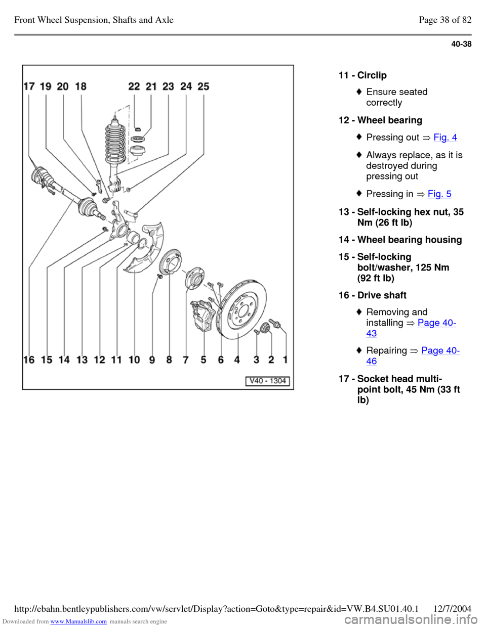
11 - Circlip Ensure seated
correctly
12 - Wheel bearing Pressing out Fig. 4 Always replace, as it is destroyed during
pressing out Pressing in Fig. 5 13 - Self-locking hex nut, 35 Nm (26 ft lb)
14 - Wheel bearing housing 15 - Self-locking
bolt/washer, 125 Nm
(92 ft lb)
16 - Drive shaft Removing and
installing Page 40-43 Repairing Page 40-46 17 - Socket head multi-
point bolt, 45 Nm (33 ft
lb) Page 38 of 82Front Wheel Suspension, Shafts and Axle12/7/2004http://ebahn.bentleypublishers.com/vw/servlet/Display?action=Goto&type=repair&id=VW.B4.SU01.40.1
Page 53 of 369
Downloaded from www.Manualslib.com manuals search engine 40-39
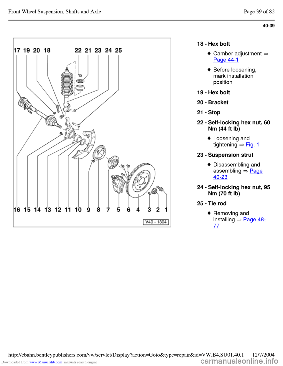
18 - Hex bolt Camber adjustment
Page 44-1 Before loosening,
mark installation
position
19 - Hex bolt
20 - Bracket
21 - Stop
22 - Self-locking hex nut, 60 Nm (44 ft lb) Loosening and
tightening Fig. 1 23 - Suspension strut Disassembling and
assembling Page 40-23 24 - Self-locking hex nut, 95 Nm (70 ft lb)
25 - Tie rod Removing and
installing Page 48-77 Page 39 of 82Front Wheel Suspension, Shafts and Axle12/7/2004http://ebahn.bentleypublishers.com/vw/servlet/Display?action=Goto&type=repair&id=VW.B4.SU01.40.1
Page 54 of 369
Downloaded from www.Manualslib.com manuals search engine 40-40
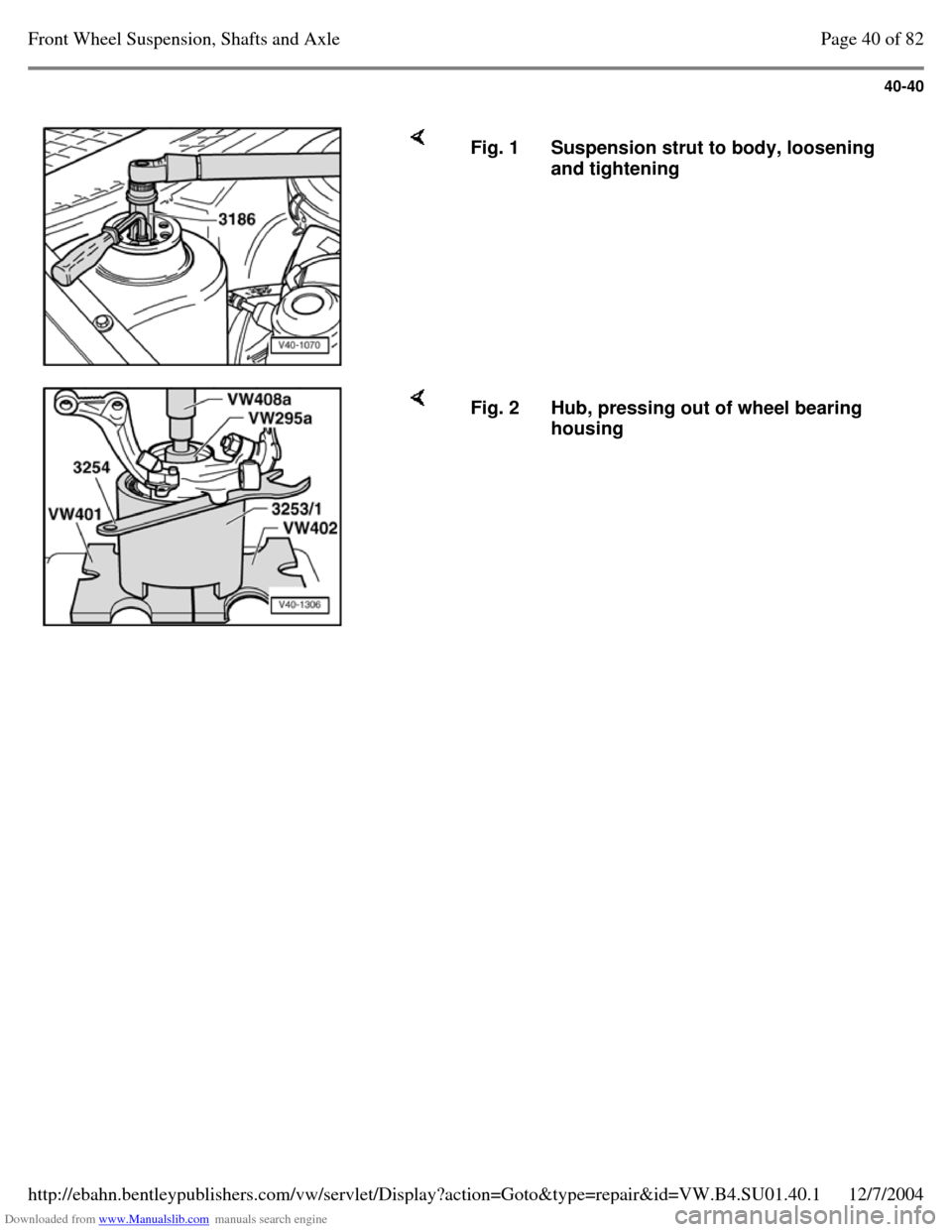
Fig. 1 Suspension strut to body, loosening
and tightening Fig. 2 Hub, pressing out of wheel bearing
housing Page 40 of 82Front Wheel Suspension, Shafts and Axle12/7/2004http://ebahn.bentleypublishers.com/vw/servlet/Display?action=Goto&type=repair&id=VW.B4.SU01.40.1
Page 55 of 369
Downloaded from www.Manualslib.com manuals search engine 40-41
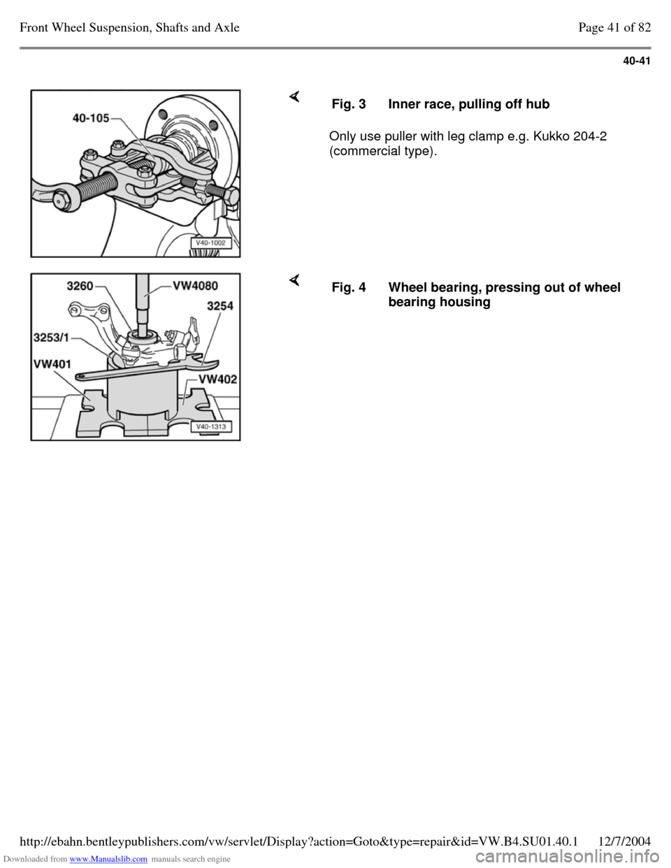
Only use puller with leg clamp e.g. Kukko 204-2
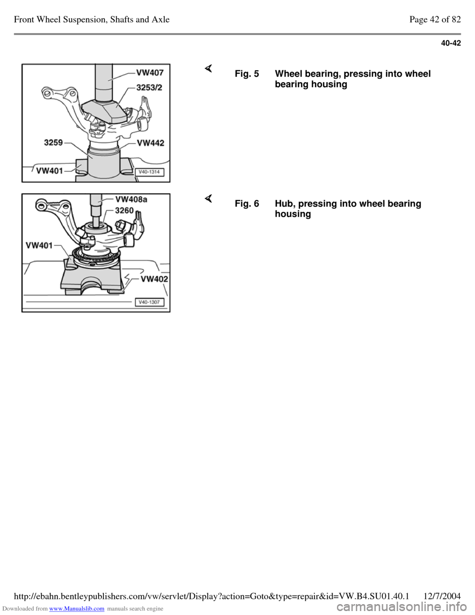
(commercial type). Fig. 3 Inner race, pulling off hub Fig. 4 Wheel bearing, pressing out of wheel
bearing housing Page 41 of 82Front Wheel Suspension, Shafts and Axle12/7/2004http://ebahn.bentleypublishers.com/vw/servlet/Display?action=Goto&type=repair&id=VW.B4.SU01.40.1
Page 56 of 369
Downloaded from www.Manualslib.com manuals search engine 40-42
Fig. 5 Wheel bearing, pressing into wheel
bearing housing Fig. 6 Hub, pressing into wheel bearing
housing Page 42 of 82Front Wheel Suspension, Shafts and Axle12/7/2004http://ebahn.bentleypublishers.com/vw/servlet/Display?action=Goto&type=repair&id=VW.B4.SU01.40.1
Page 57 of 369
Downloaded from www.Manualslib.com manuals search engine 40-43
Drive shaft, removing and installing
(Plus running gear)
Removing
- Loosen 12-point nut with vehicle standing on its
wheels.
- Disconnect drive shaft from transmission drive
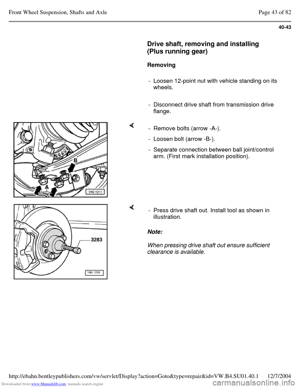
flange. - Remove bolts (arrow -A-). - Loosen bolt (arrow -B-). - Separate connection between ball joint/control
arm. (First mark installation position). Note:
When pressing drive shaft out ensure sufficient
clearance is available. - Press drive shaft out. Install tool as shown in
illustration. Page 43 of 82Front Wheel Suspension, Shafts and Axle12/7/2004http://ebahn.bentleypublishers.com/vw/servlet/Display?action=Goto&type=repair&id=VW.B4.SU01.40.1
Page 58 of 369
Downloaded from www.Manualslib.com manuals search engine 40-44
Installing
- Remove remains of locking fluid from outer joint
and hub splines. (Splines must be free of oil and
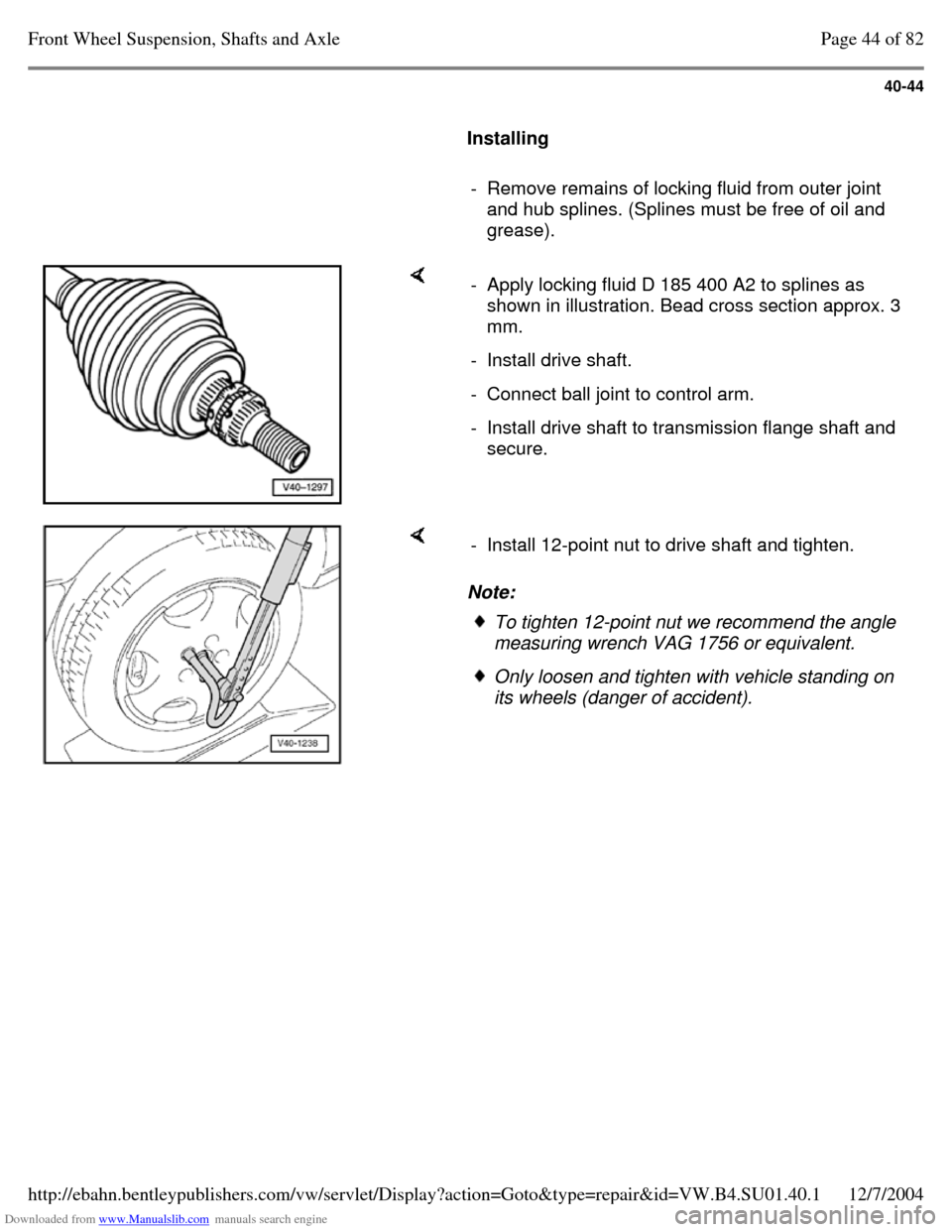
grease). - Apply locking fluid D 185 400 A2 to splines as
shown in illustration. Bead cross section approx. 3
mm.
- Install drive shaft. - Connect ball joint to control arm. - Install drive shaft to transmission flange shaft and
secure. Note: - Install 12-point nut to drive shaft and tighten. To tighten 12-point nut we recommend the angle
measuring wrench VAG 1756 or equivalent. Only loosen and tighten with vehicle standing on
its wheels (danger of accident). Page 44 of 82Front Wheel Suspension, Shafts and Axle12/7/2004http://ebahn.bentleypublishers.com/vw/servlet/Display?action=Goto&type=repair&id=VW.B4.SU01.40.1
Page 59 of 369
Downloaded from www.Manualslib.com manuals search engine 40-45
Tightening torques:
Drive shaft to flange shaft/transmission 45 Nm
(33 ft lb)
Drive shaft to wheel bearing 90 Nm (66 ft lb) and
housing turn 45 further (1
/
8 turn) Ball joint/control arm 35 Nm (26 ft lb) Page 45 of 82Front Wheel Suspension, Shafts and Axle12/7/2004http://ebahn.bentleypublishers.com/vw/servlet/Display?action=Goto&type=repair&id=VW.B4.SU01.40.1
Page 60 of 369
Downloaded from www.Manualslib.com manuals search engine 40-46
Drive shaft, repairing
Drive shafts on vehicles with Plus suspension
have shorter and finer splines on the outer joint.
The wheel bearing is secured by a 12-point nut.
The splines of the outer joint and the hub on Plus
suspensions are secured with locking fluid D 185
400 A2.
Drive shaft, removing and installing
Vehicles with Base suspension Page 40-14 Vehicles with Plus suspension Page 40-43
Note:
Grease quantity:
- - Outer constant velocity joint 100 g of G-6.3
grease
- - Inner constant velocity joint 110 g of G-6.3
grease
Greasing outer joint: press half of the grease
into the joint, and the other half evenly into the
boot.
Greasing inner joint: press half of the grease
into the inner joint from both sides, the other
half evenly into the boot.
When replacing the boot grease joint as
required. Page 46 of 82Front Wheel Suspension, Shafts and Axle12/7/2004http://ebahn.bentleypublishers.com/vw/servlet/Display?action=Goto&type=repair&id=VW.B4.SU01.40.1
