engine VOLKSWAGEN PASSAT 1996 B3, B4 / 3.G Service Owners Manual
[x] Cancel search | Manufacturer: VOLKSWAGEN, Model Year: 1996, Model line: PASSAT, Model: VOLKSWAGEN PASSAT 1996 B3, B4 / 3.GPages: 369, PDF Size: 12.33 MB
Page 91 of 369
Downloaded from www.Manualslib.com manuals search engine 40-77
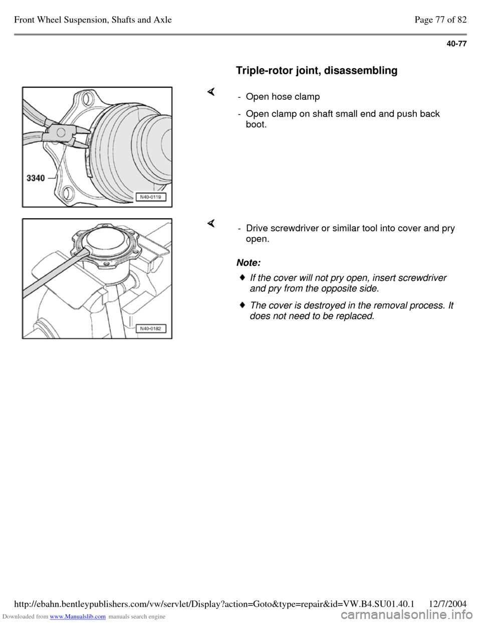
Triple-rotor joint, disassembling - Open hose clamp - Open clamp on shaft small end and push back
boot. Note: - Drive screwdriver or similar tool into cover and pry
open. If the cover will not pry open, insert screwdriver
and pry from the opposite side. The cover is destroyed in the removal process. It
does not need to be replaced. Page 77 of 82Front Wheel Suspension, Shafts and Axle12/7/2004http://ebahn.bentleypublishers.com/vw/servlet/Display?action=Goto&type=repair&id=VW.B4.SU01.40.1
Page 92 of 369
Downloaded from www.Manualslib.com manuals search engine 40-78
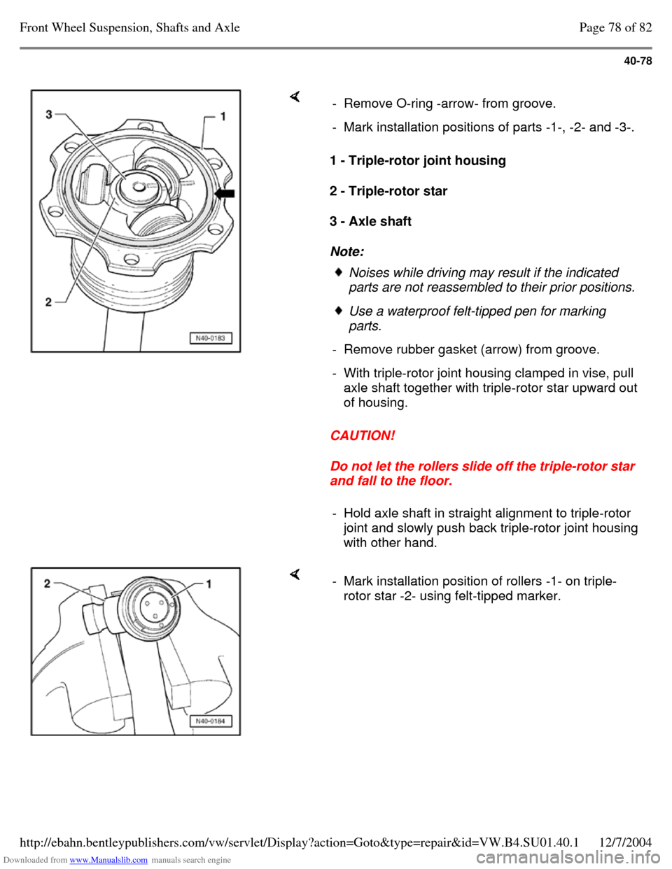
1 - Triple-rotor joint housing
2 - Triple-rotor star
3 - Axle shaft
Note:
CAUTION!
Do not let the rollers slide off the triple-rotor star
and fall to the floor. - Remove O-ring -arrow- from groove. - Mark installation positions of parts -1-, -2- and -3-. Noises while driving may result if the indicated
parts are not reassembled to their prior positions. Use a waterproof felt-tipped pen for marking
parts.
- Remove rubber gasket (arrow) from groove. - With triple-rotor joint housing clamped in vise, pull
axle shaft together with triple-rotor star upward out
of housing.
- Hold axle shaft in straight alignment to triple-rotor
joint and slowly push back triple-rotor joint housing
with other hand. - Mark installation position of rollers -1- on triple-
rotor star -2- using felt-tipped marker. Page 78 of 82Front Wheel Suspension, Shafts and Axle12/7/2004http://ebahn.bentleypublishers.com/vw/servlet/Display?action=Goto&type=repair&id=VW.B4.SU01.40.1
Page 93 of 369
Downloaded from www.Manualslib.com manuals search engine 40-79
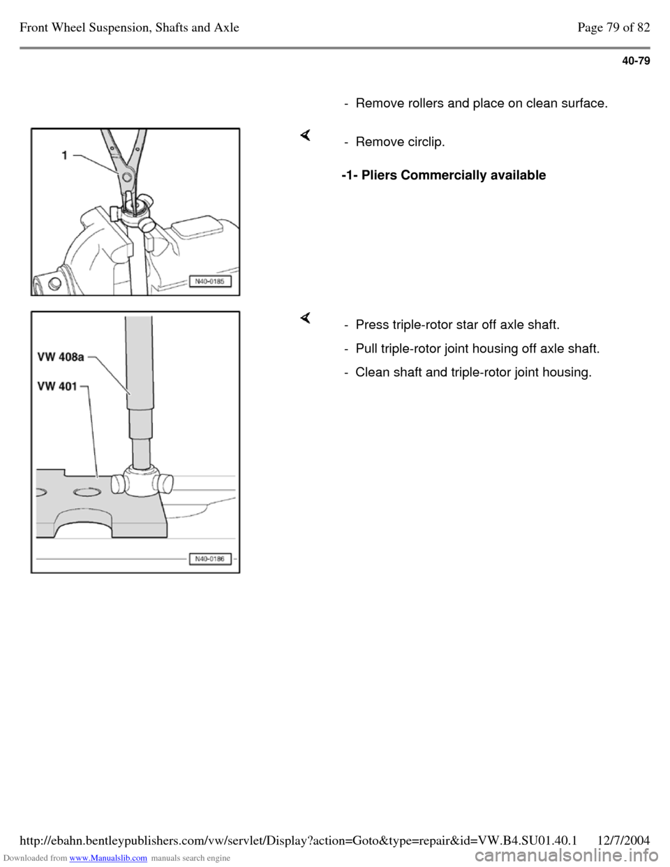
- Remove rollers and place on clean surface. -1- Pliers Commercially available - Remove circlip. - Press triple-rotor star off axle shaft. - Pull triple-rotor joint housing off axle shaft. - Clean shaft and triple-rotor joint housing. Page 79 of 82Front Wheel Suspension, Shafts and Axle12/7/2004http://ebahn.bentleypublishers.com/vw/servlet/Display?action=Goto&type=repair&id=VW.B4.SU01.40.1
Page 94 of 369
Downloaded from www.Manualslib.com manuals search engine 40-80
Triple-rotor joint, assembling
- Slide small diameter boot clamp onto shaft.
- Slide triple-rotor joint boot onto shaft.
- Slide triple-rotor joint housing onto shaft.
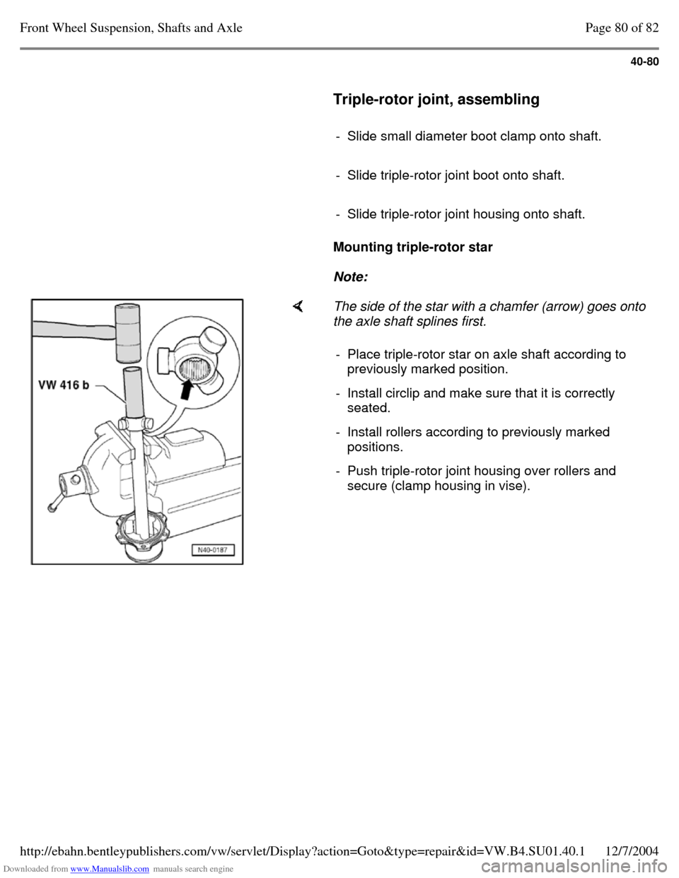
Mounting triple-rotor star
Note: The side of the star with a chamfer (arrow) goes onto
the axle shaft splines first.
- Place triple-rotor star on axle shaft according to
previously marked position.
- Install circlip and make sure that it is correctly
seated.
- Install rollers according to previously marked
positions.
- Push triple-rotor joint housing over rollers and
secure (clamp housing in vise). Page 80 of 82Front Wheel Suspension, Shafts and Axle12/7/2004http://ebahn.bentleypublishers.com/vw/servlet/Display?action=Goto&type=repair&id=VW.B4.SU01.40.1
Page 95 of 369
Downloaded from www.Manualslib.com manuals search engine 40-81
Note:
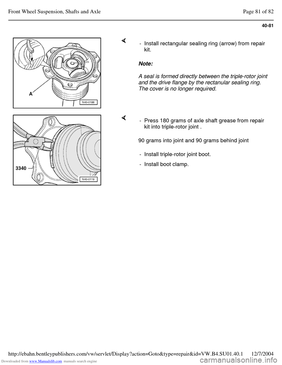
A seal is formed directly between the triple-rotor joint
and the drive flange by the rectanular sealing ring.
The cover is no longer required. - Install rectangular sealing ring (arrow) from repair
kit. 90 grams into joint and 90 grams behind joint - Press 180 grams of axle shaft grease from repair
kit into triple-rotor joint .
- Install triple-rotor joint boot. - Install boot clamp. Page 81 of 82Front Wheel Suspension, Shafts and Axle12/7/2004http://ebahn.bentleypublishers.com/vw/servlet/Display?action=Goto&type=repair&id=VW.B4.SU01.40.1
Page 96 of 369
Downloaded from www.Manualslib.com manuals search engine 40-82
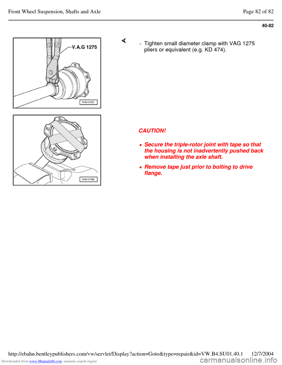
- Tighten small diameter clamp with VAG 1275
pliers or equivalent (e.g. KD 474).
CAUTION! Secure the triple-rotor joint with tape so that
the housing is not inadvertently pushed back
when installing the axle shaft. Remove tape just prior to bolting to drive
flange. Page 82 of 82Front Wheel Suspension, Shafts and Axle12/7/2004http://ebahn.bentleypublishers.com/vw/servlet/Display?action=Goto&type=repair&id=VW.B4.SU01.40.1
Page 97 of 369
Downloaded from www.Manualslib.com manuals search engine 42-1
Rear Wheel
Suspension, Shafts
and Axle
Rear axle, servicing
(vehicles with front wheel
drive)
Note: The rear axle and wheel
bearings are identical on
Base and Plus suspension
versions. Welding and straightening
of the axle beam is not
permissible.
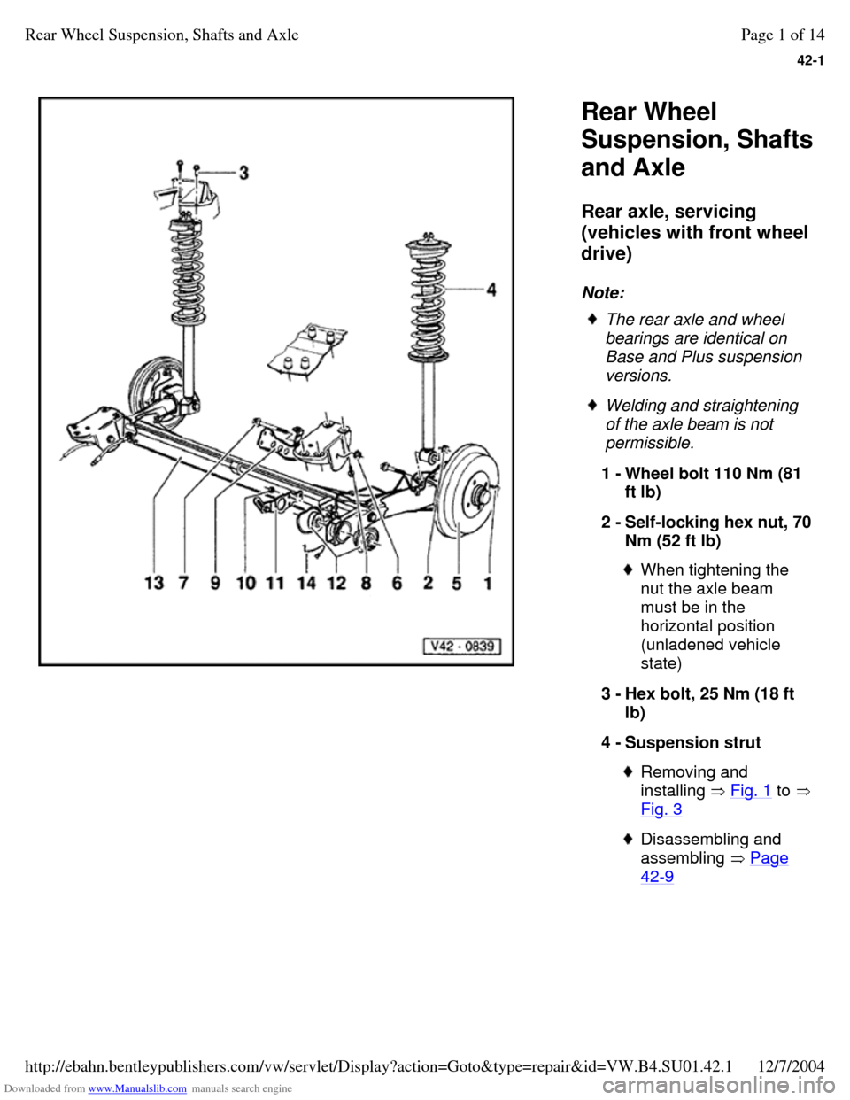
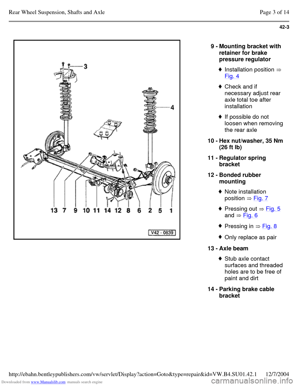
1 - Wheel bolt 110 Nm (81
ft lb)
2 - Self-locking hex nut, 70 Nm (52 ft lb) When tightening the
nut the axle beam
must be in the
horizontal position
(unladened vehicle
state)
3 - Hex bolt, 25 Nm (18 ft
lb)
4 - Suspension strut Removing and
installing Fig. 1 to Fig. 3 Disassembling and
assembling Page 42-9 Page 1 of 14Rear Wheel Suspension, Shafts and Axle12/7/2004http://ebahn.bentleypublishers.com/vw/servlet/Display?action=Goto&type=repair&id=VW.B4.SU01.42.1
Page 98 of 369
Downloaded from www.Manualslib.com manuals search engine 42-2
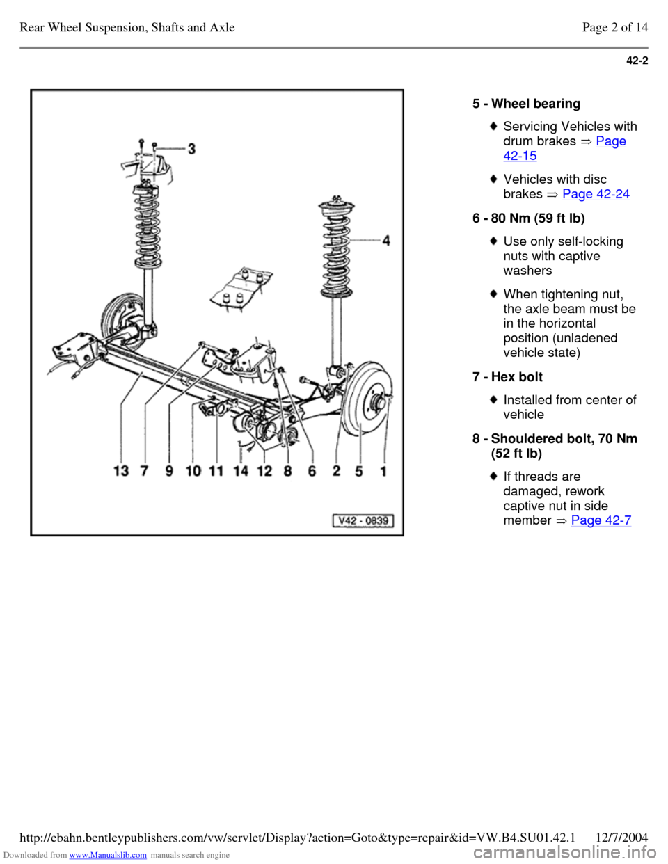
5 - Wheel bearing Servicing Vehicles with drum brakes Page 42-15 Vehicles with disc
brakes Page 42-24 6 - 80 Nm (59 ft lb) Use only self-locking
nuts with captive
washers When tightening nut, the axle beam must be in the horizontal
position (unladened
vehicle state)
7 - Hex bolt Installed from center of vehicle
8 - Shouldered bolt, 70 Nm (52 ft lb) If threads are
damaged, rework
captive nut in side
member Page 42-7 Page 2 of 14Rear Wheel Suspension, Shafts and Axle12/7/2004http://ebahn.bentleypublishers.com/vw/servlet/Display?action=Goto&type=repair&id=VW.B4.SU01.42.1
Page 99 of 369
Downloaded from www.Manualslib.com manuals search engine 42-3
9 - Mounting bracket with
retainer for brake
pressure regulator Installation position
Fig. 4 Check and if
necessary adjust rear
axle total toe after
installation If possible do not
loosen when removing
the rear axle
10 - Hex nut/washer, 35 Nm
(26 ft lb)
11 - Regulator spring
bracket
12 - Bonded rubber
mounting Note installation
position Fig. 7 Pressing out Fig. 5
and Fig. 6 Pressing in Fig. 8 Only replace as pair 13 - Axle beam Stub axle contact
surfaces and threaded
holes are to be free of
paint and dirt
14 - Parking brake cable
bracket Page 3 of 14Rear Wheel Suspension, Shafts and Axle12/7/2004http://ebahn.bentleypublishers.com/vw/servlet/Display?action=Goto&type=repair&id=VW.B4.SU01.42.1
Page 100 of 369
Downloaded from www.Manualslib.com manuals search engine 42-4
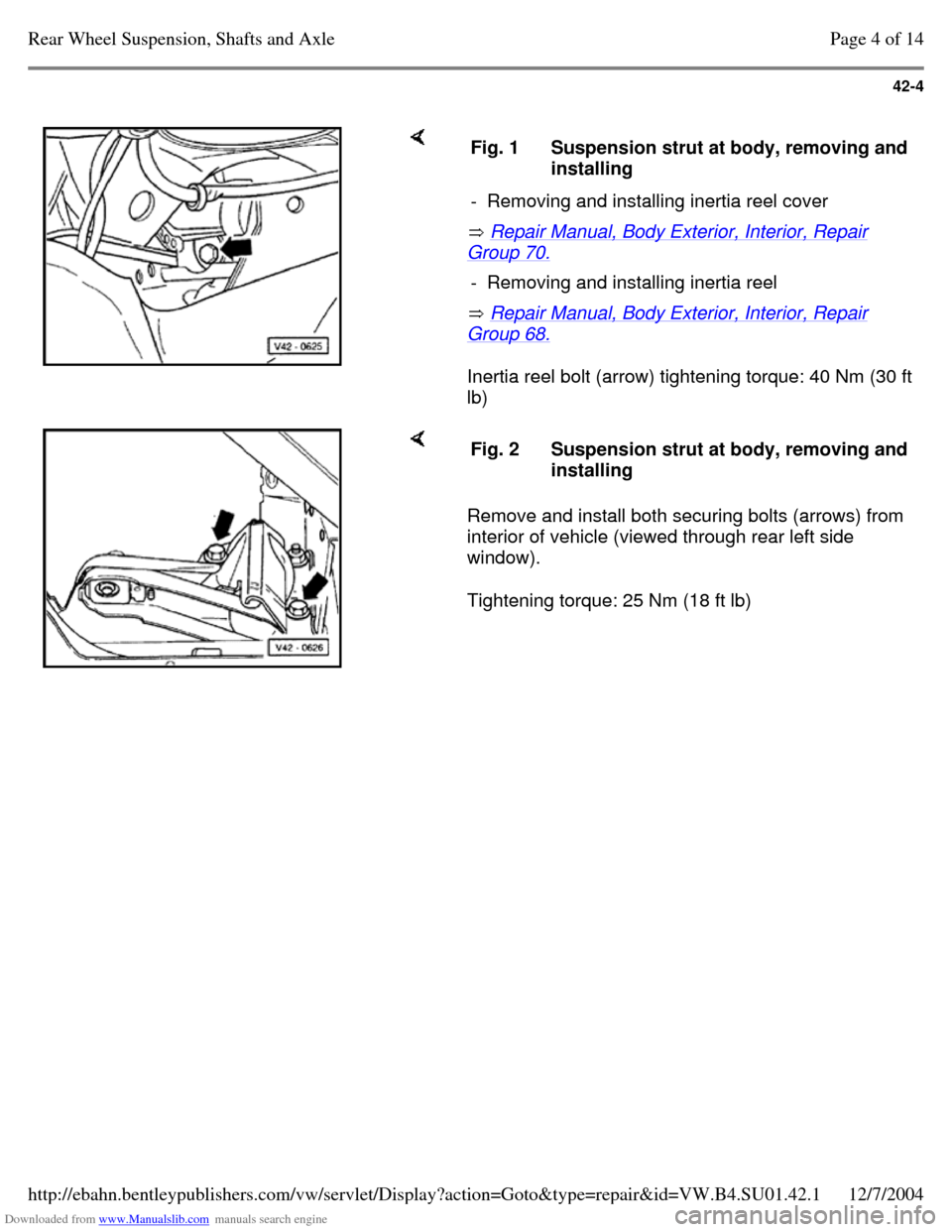
Repair Manual, Body Exterior, Interior, Repair Group 70.
Repair Manual, Body Exterior, Interior, Repair Group 68.
Inertia reel bolt (arrow) tightening torque: 40 Nm (30 ft
lb) Fig. 1 Suspension strut at body, removing and installing
- Removing and installing inertia reel cover - Removing and installing inertia reel Remove and install both securing bolts (arrows) from
interior of vehicle (viewed through rear left side
window).
Tightening torque: 25 Nm (18 ft lb) Fig. 2 Suspension strut at body, removing and installing Page 4 of 14Rear Wheel Suspension, Shafts and Axle12/7/2004http://ebahn.bentleypublishers.com/vw/servlet/Display?action=Goto&type=repair&id=VW.B4.SU01.42.1