ECU VOLKSWAGEN PASSAT 1997 B3, B4 / 3.G Service Workshop Manual
[x] Cancel search | Manufacturer: VOLKSWAGEN, Model Year: 1997, Model line: PASSAT, Model: VOLKSWAGEN PASSAT 1997 B3, B4 / 3.GPages: 369, PDF Size: 12.33 MB
Page 17 of 369
Downloaded from www.Manualslib.com manuals search engine 40-3
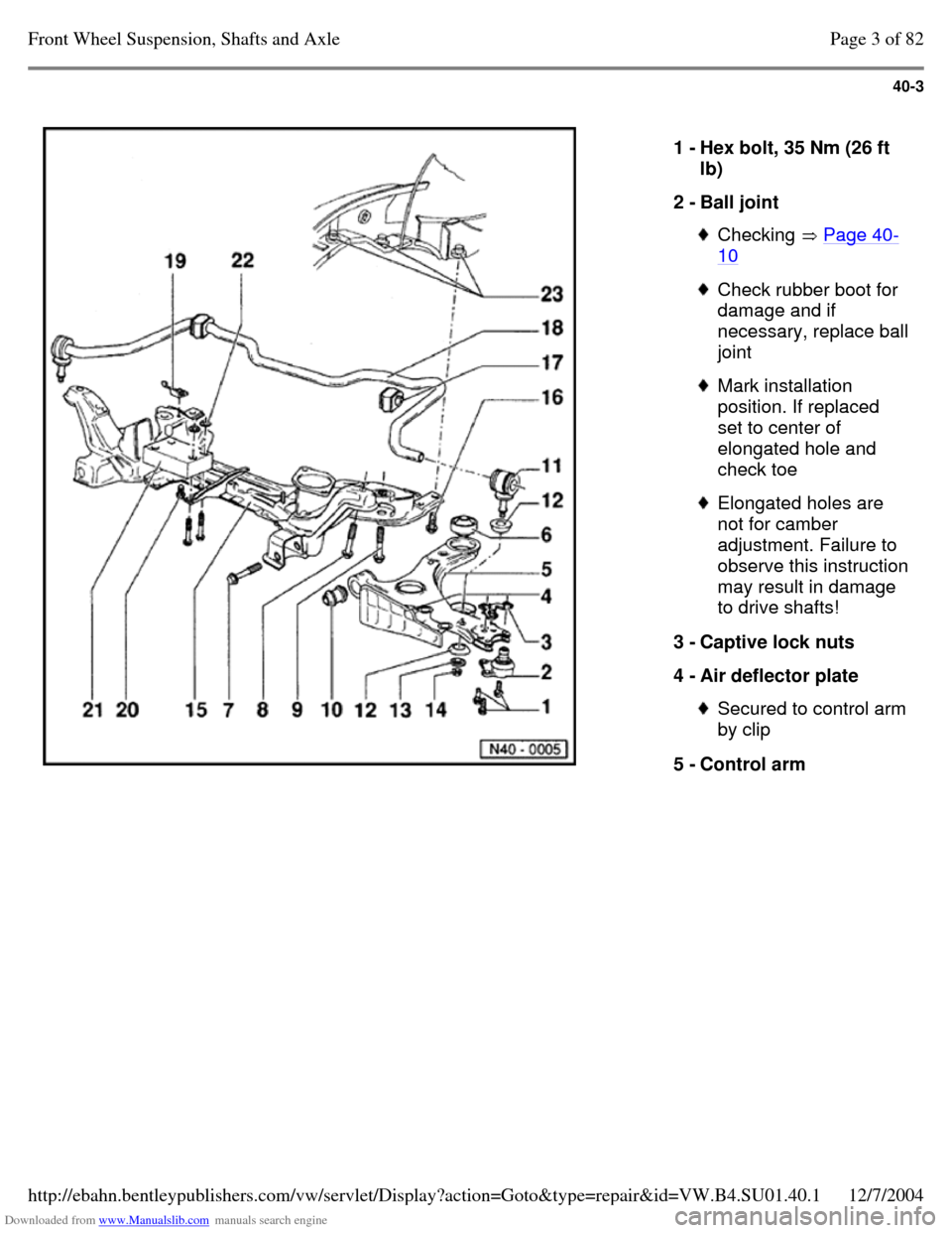
1 - Hex bolt, 35 Nm (26 ft
lb)
2 - Ball joint Checking Page 40-10 Check rubber boot for
damage and if necessary, replace ball joint Mark installation
position. If replaced
set to center of
elongated hole and
check toe Elongated holes are
not for camber
adjustment. Failure to observe this instruction may result in damage
to drive shafts!
3 - Captive lock nuts
4 - Air deflector plate Secured to control arm by clip
5 - Control arm Page 3 of 82Front Wheel Suspension, Shafts and Axle12/7/2004http://ebahn.bentleypublishers.com/vw/servlet/Display?action=Goto&type=repair&id=VW.B4.SU01.40.1
Page 20 of 369
Downloaded from www.Manualslib.com manuals search engine 40-6
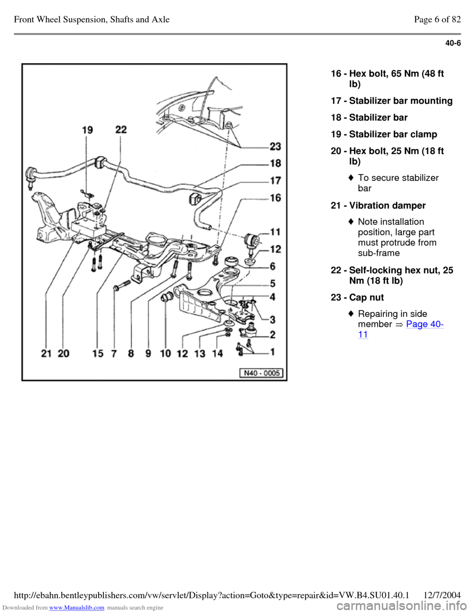
16 - Hex bolt, 65 Nm (48 ft
lb)
17 - Stabilizer bar mounting 18 - Stabilizer bar
19 - Stabilizer bar clamp
20 - Hex bolt, 25 Nm (18 ft
lb) To secure stabilizer
bar
21 - Vibration damper Note installation
position, large part
must protrude from
sub-frame
22 - Self-locking hex nut, 25 Nm (18 ft lb)
23 - Cap nut Repairing in side
member Page 40-11 Page 6 of 82Front Wheel Suspension, Shafts and Axle12/7/2004http://ebahn.bentleypublishers.com/vw/servlet/Display?action=Goto&type=repair&id=VW.B4.SU01.40.1
Page 25 of 369
Downloaded from www.Manualslib.com manuals search engine 40-11
Reworking cap nut in side member
(Base and Plus suspension)
If the threads of the cap nut in the side member
are damaged, the thread must either be retapped
or the cap nut must be drilled out.
When drilling out proceed as follows.
- Support engine/transmission assembly with 10-
222 A and legs 10-222 A/1.
- Remove the sub-frame.
- Drill out the damaged side member cap nut with
a 10.2 mm diameter drill from underneath.
Note:
When drilling do not tilt the drill.
WARNING!
Wear protective goggles.
- Cut new M 12 x 1.5 thread in cap nut.
- Use a new bolt/washer assembly to secure sub-
frame Page 40-13 . Page 11 of 82Front Wheel Suspension, Shafts and Axle12/7/2004http://ebahn.bentleypublishers.com/vw/servlet/Display?action=Goto&type=repair&id=VW.B4.SU01.40.1
Page 26 of 369
Downloaded from www.Manualslib.com manuals search engine 40-12
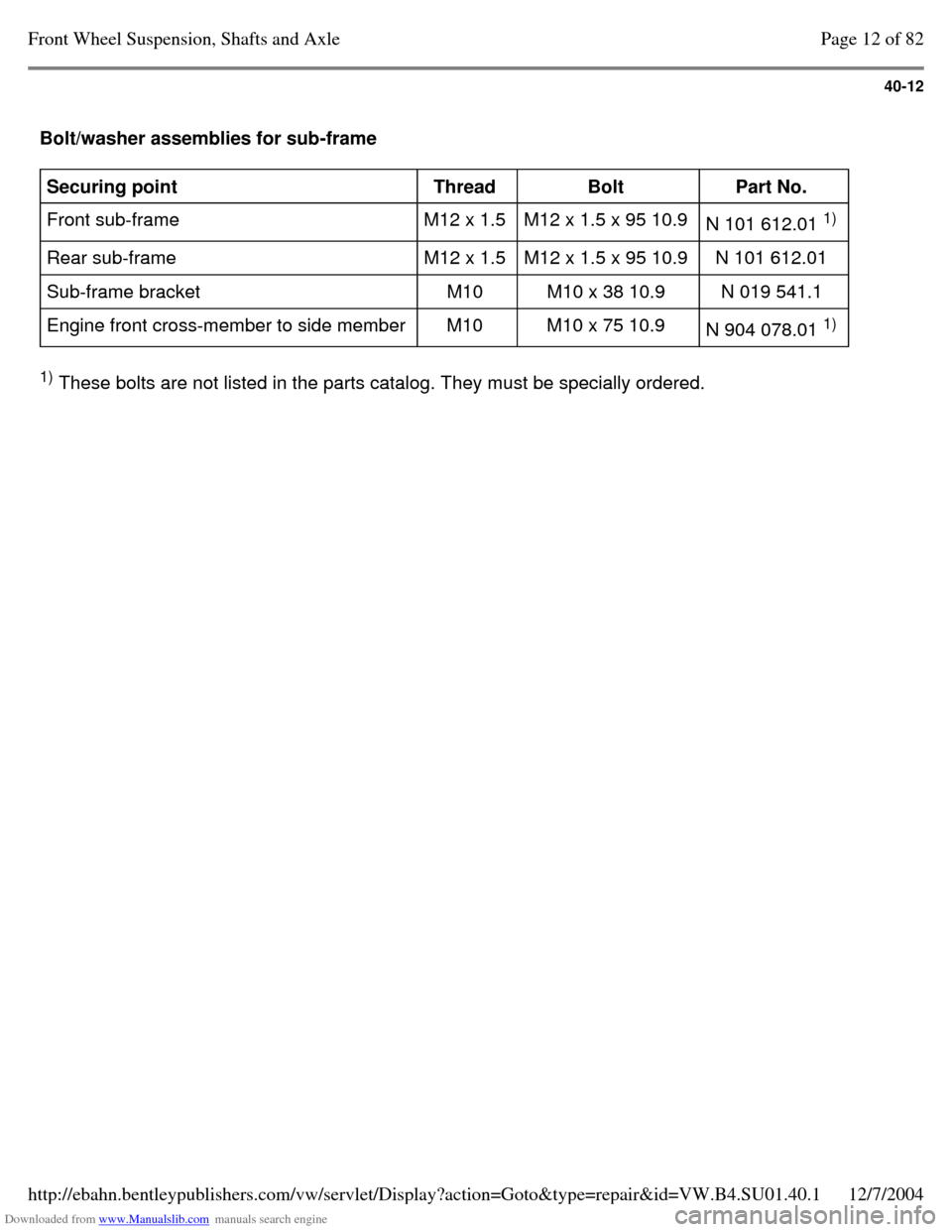
Bolt/washer assemblies for sub-frame Securing point
Thread
Bolt
Part No.
Front sub-frame M12 x 1.5 M12 x 1.5 x 95 10.9
N 101 612.01 1)
Rear sub-frame M12 x 1.5 M12 x 1.5 x 95 10.9 N 101 612.01
Sub-frame bracket M10 M10 x 38 10.9 N 019 541.1
Engine front cross-member to side member M10 M10 x 75 10.9
N 904 078.01 1)
1)
These bolts are not listed in the parts catalog. They must be specially ordered. Page 12 of 82Front Wheel Suspension, Shafts and Axle12/7/2004http://ebahn.bentleypublishers.com/vw/servlet/Display?action=Goto&type=repair&id=VW.B4.SU01.40.1
Page 31 of 369
Downloaded from www.Manualslib.com manuals search engine 40-17
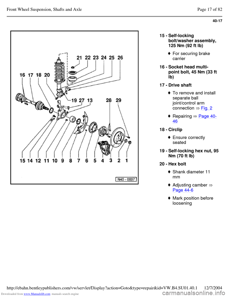
15 - Self-locking
bolt/washer assembly,
125 Nm (92 ft lb) For securing brake
carrier
16 - Socket head multi-
point bolt, 45 Nm (33 ft
lb)
17 - Drive shaft To remove and install
separate ball
joint/control arm
connection Fig. 2 Repairing Page 40-46 18 - Circlip Ensure correctly
seated
19 - Self-locking hex nut, 95 Nm (70 ft lb)
20 - Hex bolt Shank diameter 11
mm Adjusting camber
Page 44-6 Mark position before
loosening Page 17 of 82Front Wheel Suspension, Shafts and Axle12/7/2004http://ebahn.bentleypublishers.com/vw/servlet/Display?action=Goto&type=repair&id=VW.B4.SU01.40.1
Page 42 of 369
Downloaded from www.Manualslib.com manuals search engine 40-28
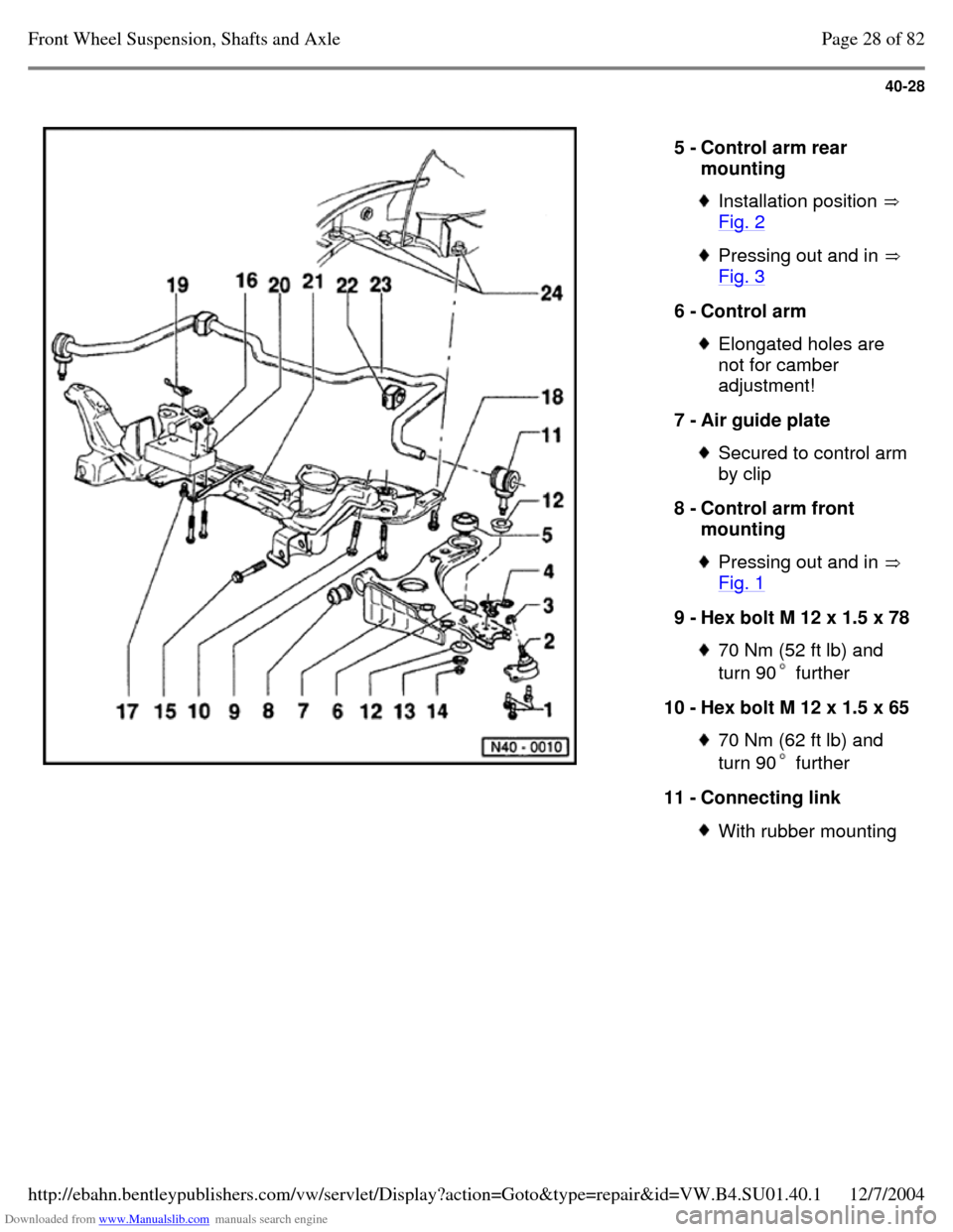
5 - Control arm rear
mounting Installation position
Fig. 2 Pressing out and in
Fig. 3 6 - Control arm Elongated holes are
not for camber
adjustment!
7 - Air guide plate Secured to control arm by clip
8 - Control arm front
mounting Pressing out and in
Fig. 1 9 - Hex bolt M 12 x 1.5 x 78 70 Nm (52 ft lb) and
turn 90 further 10 - Hex bolt M 12 x 1.5 x 65 70 Nm (62 ft lb) and
turn 90 further 11 - Connecting link With rubber mounting Page 28 of 82Front Wheel Suspension, Shafts and Axle12/7/2004http://ebahn.bentleypublishers.com/vw/servlet/Display?action=Goto&type=repair&id=VW.B4.SU01.40.1
Page 43 of 369
Downloaded from www.Manualslib.com manuals search engine 40-29
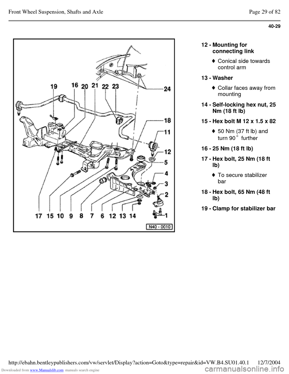
12 - Mounting for
connecting link Conical side towards
control arm
13 - Washer Collar faces away from mounting
14 - Self-locking hex nut, 25 Nm (18 ft lb)
15 - Hex bolt M 12 x 1.5 x 82 50 Nm (37 ft lb) and
turn 90 further 16 - 25 Nm (18 ft lb)
17 - Hex bolt, 25 Nm (18 ft
lb) To secure stabilizer
bar
18 - Hex bolt, 65 Nm (48 ft
lb)
19 - Clamp for stabilizer bar Page 29 of 82Front Wheel Suspension, Shafts and Axle12/7/2004http://ebahn.bentleypublishers.com/vw/servlet/Display?action=Goto&type=repair&id=VW.B4.SU01.40.1
Page 48 of 369
Downloaded from www.Manualslib.com manuals search engine 40-34
Note:
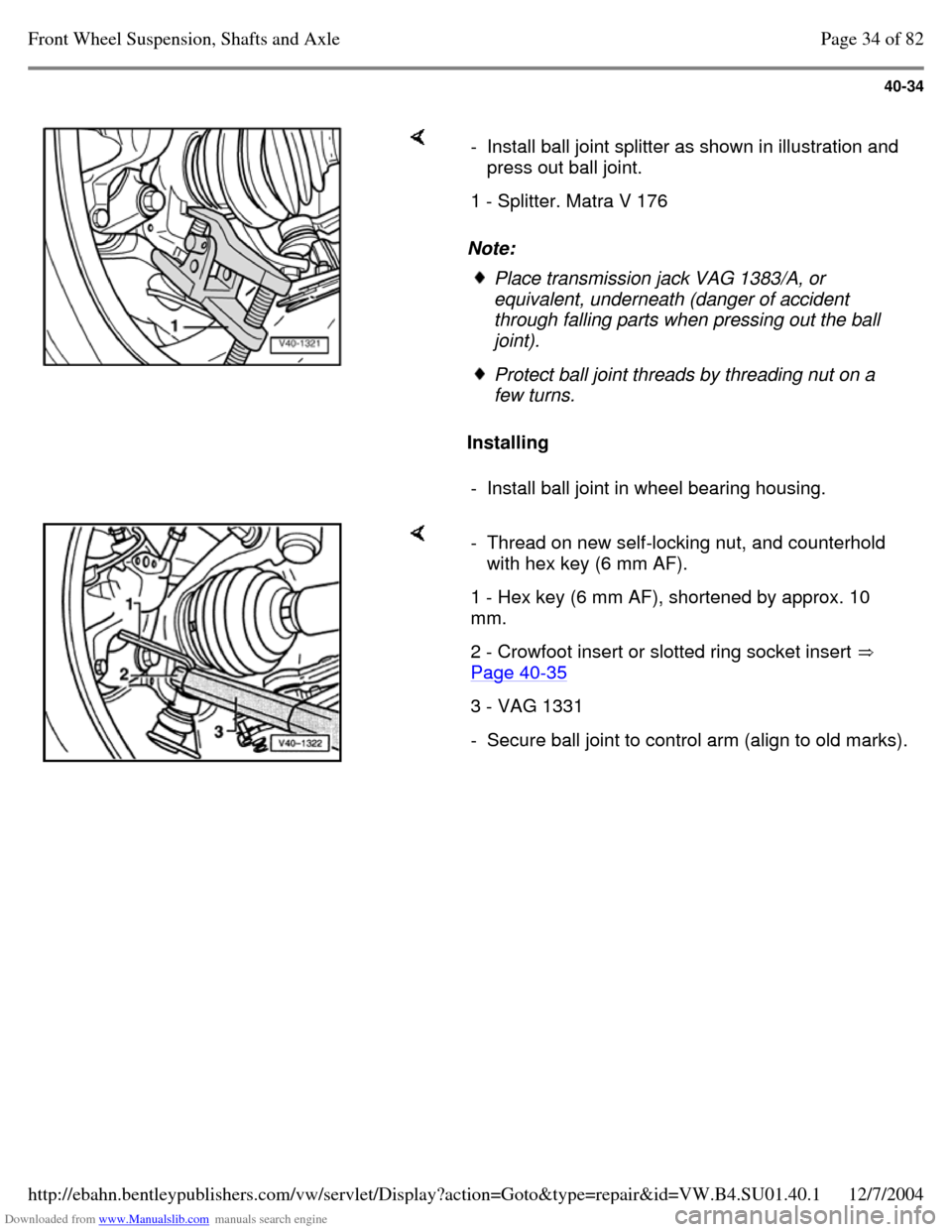
Installing - Install ball joint splitter as shown in illustration and
press out ball joint.
1 - Splitter. Matra V 176 Place transmission jack VAG 1383/A, or
equivalent, underneath (danger of accident
through falling parts when pressing out the ball joint). Protect ball joint threads by threading nut on a
few turns.
- Install ball joint in wheel bearing housing. - Thread on new self-locking nut, and counterhold
with hex key (6 mm AF).
1 - Hex key (6 mm AF), shortened by approx. 10
mm.
2 - Crowfoot insert or slotted ring socket insert
Page 40-35 3 - VAG 1331 - Secure ball joint to control arm (align to old marks). Page 34 of 82Front Wheel Suspension, Shafts and Axle12/7/2004http://ebahn.bentleypublishers.com/vw/servlet/Display?action=Goto&type=repair&id=VW.B4.SU01.40.1
Page 58 of 369
Downloaded from www.Manualslib.com manuals search engine 40-44
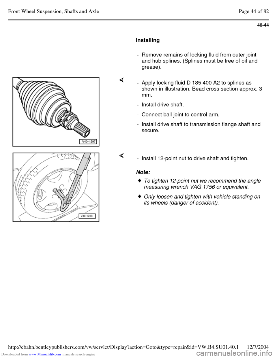
Installing
- Remove remains of locking fluid from outer joint
and hub splines. (Splines must be free of oil and
grease). - Apply locking fluid D 185 400 A2 to splines as
shown in illustration. Bead cross section approx. 3
mm.
- Install drive shaft. - Connect ball joint to control arm. - Install drive shaft to transmission flange shaft and
secure. Note: - Install 12-point nut to drive shaft and tighten. To tighten 12-point nut we recommend the angle
measuring wrench VAG 1756 or equivalent. Only loosen and tighten with vehicle standing on
its wheels (danger of accident). Page 44 of 82Front Wheel Suspension, Shafts and Axle12/7/2004http://ebahn.bentleypublishers.com/vw/servlet/Display?action=Goto&type=repair&id=VW.B4.SU01.40.1
Page 60 of 369
Downloaded from www.Manualslib.com manuals search engine 40-46
Drive shaft, repairing
Drive shafts on vehicles with Plus suspension
have shorter and finer splines on the outer joint.
The wheel bearing is secured by a 12-point nut.
The splines of the outer joint and the hub on Plus
suspensions are secured with locking fluid D 185
400 A2.
Drive shaft, removing and installing
Vehicles with Base suspension Page 40-14 Vehicles with Plus suspension Page 40-43
Note:
Grease quantity:
- - Outer constant velocity joint 100 g of G-6.3
grease
- - Inner constant velocity joint 110 g of G-6.3
grease
Greasing outer joint: press half of the grease
into the joint, and the other half evenly into the
boot.
Greasing inner joint: press half of the grease
into the inner joint from both sides, the other
half evenly into the boot.
When replacing the boot grease joint as
required. Page 46 of 82Front Wheel Suspension, Shafts and Axle12/7/2004http://ebahn.bentleypublishers.com/vw/servlet/Display?action=Goto&type=repair&id=VW.B4.SU01.40.1