check engine light VOLKSWAGEN PASSAT 1997 B3, B4 / 3.G Service Workshop Manual
[x] Cancel search | Manufacturer: VOLKSWAGEN, Model Year: 1997, Model line: PASSAT, Model: VOLKSWAGEN PASSAT 1997 B3, B4 / 3.GPages: 369, PDF Size: 12.33 MB
Page 5 of 369

Downloaded from www.Manualslib.com manuals search engine Front brakes, servicing (Teves/Ate)
Brake pads, removing and installing
Rear wheel brakes, servicing (drum brakes)
Brake shoe adjustment, releasing
Rear wheel brakes, servicing
Brake shoes, removing and installing
Parking brake, adjusting (drum brakes)
Rear wheel brakes, servicing (disc brakes)
Girling rear wheel disc brakes (front and four wheel drive vehicles)
Brake pads, removing and installing
Parking brake, adjusting (disc brakes)
Parking brake lever assembly overview
Brake pedal/brake servo, removing and installing
Brake pedal, removing and installing
Brake Light Switch, adjusting
47 - Brakes - Hydraulic components
Assembly overview: brake master cylinder/brake servo
Girling front brake caliper, servicing
Front brake caliper pistons, removing and installing
Front brake caliper, servicing (Teves/Ate)
Rear brake caliper, servicing
Rear brake caliper piston, removing and installing
Pre-bleeding brake caliper
Brake pressure regulator, checking and adjusting
Vehicles without ABS, vehicles with ABS, ABS/EDS, Teves 04
Load dependent brake pressure regulator specifications
Adjusting regulator
Brake system, bleeding
Brake system, bleeding (vehicles with and without ABS, ABS/EDL)
Brake system, bleeding (with pressure bleeder VAS 5234)
Brake system, bleeding (without pressure bleeder)
Page 168 of 369
Downloaded from www.Manualslib.com manuals search engine 44-6
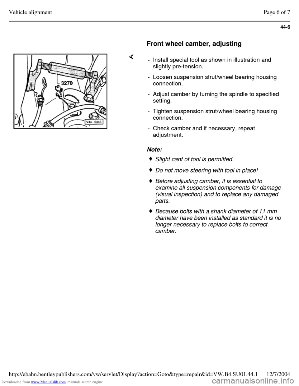
Front wheel camber, adjusting Note: - Install special tool as shown in illustration and
slightly pre-tension.
- Loosen suspension strut/wheel bearing housing
connection.
- Adjust camber by turning the spindle to specified
setting.
- Tighten suspension strut/wheel bearing housing
connection.
- Check camber and if necessary, repeat
adjustment. Slight cant of tool is permitted. Do not move steering with tool in place! Before adjusting camber, it is essential to
examine all suspension components for damage
(visual inspection) and to replace any damaged
parts. Because bolts with a shank diameter of 11 mm
diameter have been installed as standard it is no
longer necessary to replace bolts to correct
camber. Page 6 of 7Vehicle alignment12/7/2004http://ebahn.bentleypublishers.com/vw/servlet/Display?action=Goto&type=repair&id=VW.B4.SU01.44.1
Page 241 of 369
Downloaded from www.Manualslib.com manuals search engine 46-45
Brake Light Switch, adjusting
Note:
The Brake Light Switch must be removed for
adjusting.
- Remove trim under instrument panel.
- Disconnect harness connector for Brake Light
Switch.
- Remove Brake Light Switch by turning to right
through 90.
- Pull Brake Light Switch plunger fully out.
- Depress brake pedal as far as possible by hand,
guide Brake Light Switch through the locating
hole and secure by turning through 90to left.
- Pull brake pedal back up by hand to stop (Brake
Light Switch is pushed back by one notch).
- Connect harness connector for Brake Light
Switch
- Check function of Brake Light Switch.
- Install instrument panel trim. Page 9 of 9Parking brake lever assembly overview12/7/2004http://ebahn.bentleypublishers.com/vw/servlet/Display?action=Goto&type=repair&id=VW.B4.SU01.46.6
Page 243 of 369
Downloaded from www.Manualslib.com manuals search engine 47-2
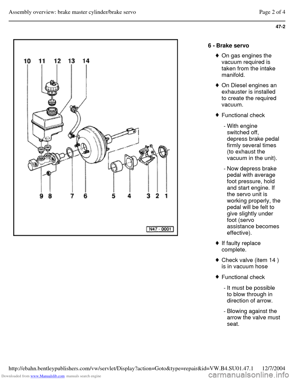
6 - Brake servo On gas engines the
vacuum required is
taken from the intake
manifold. On Diesel engines an
exhauster is installed
to create the required
vacuum. Functional check - With engine
switched off,
depress brake pedal
firmly several times
(to exhaust the
vacuum in the unit).
- Now depress brake
pedal with average
foot pressure, hold
and start engine. If
the servo unit is working properly, the pedal will be felt to
give slightly under
foot (servo
assistance becomes
effective). If faulty replace
complete. Check valve (item 14 )
is in vacuum hose Functional check - It must be possible
to blow through in
direction of arrow.
- Blowing against the arrow the valve must seat. Page 2 of 4Assembly overview: brake master cylinder/brake servo12/7/2004http://ebahn.bentleypublishers.com/vw/servlet/Display?action=Goto&type=repair&id=VW.B4.SU01.47.1
Page 310 of 369
Downloaded from www.Manualslib.com manuals search engine 48-40
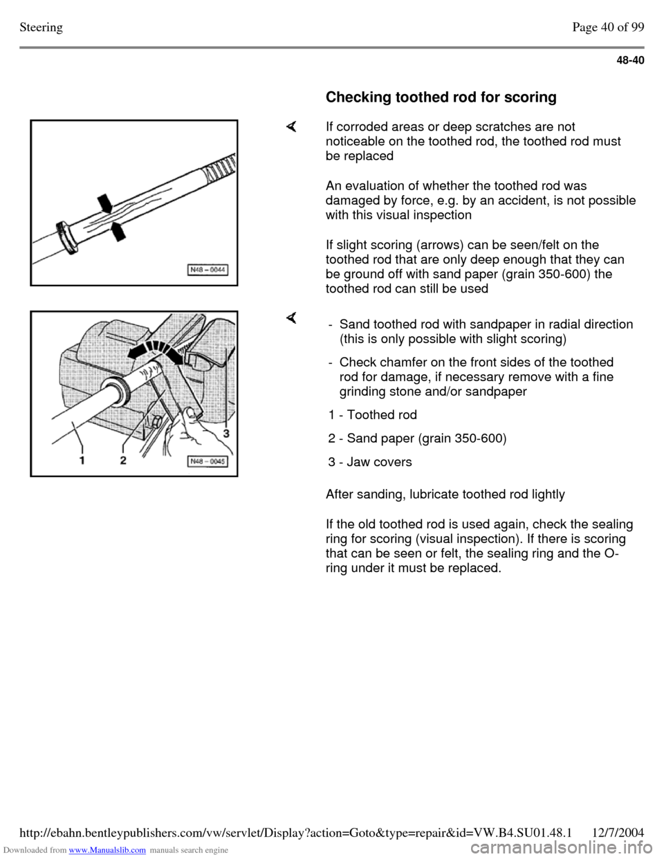
Checking toothed rod for scoring If corroded areas or deep scratches are not
noticeable on the toothed rod, the toothed rod must
be replaced
An evaluation of whether the toothed rod was
damaged by force, e.g. by an accident, is not possible
with this visual inspection
If slight scoring (arrows) can be seen/felt on the
toothed rod that are only deep enough that they can
be ground off with sand paper (grain 350-600) the
toothed rod can still be used After sanding, lubricate toothed rod lightly
If the old toothed rod is used again, check the sealing
ring for scoring (visual inspection). If there is scoring
that can be seen or felt, the sealing ring and the O-
ring under it must be replaced. - Sand toothed rod with sandpaper in radial direction (this is only possible with slight scoring)
- Check chamfer on the front sides of the toothed
rod for damage, if necessary remove with a fine
grinding stone and/or sandpaper
1 - Toothed rod 2 - Sand paper (grain 350-600) 3 - Jaw covers Page 40 of 99Steering12/7/2004http://ebahn.bentleypublishers.com/vw/servlet/Display?action=Goto&type=repair&id=VW.B4.SU01.48.1
Page 323 of 369
Downloaded from www.Manualslib.com manuals search engine 48-53
Needle run-out max. 0.10 mm
If needle run-out is greater than 0.10 mm, screw
pressure piece slightly into housing
If the needle run-out is less than 0.10 mm, screw
pressure piece slightly out of housing
- Tighten lock nut
- Check needle run-out again, if necessary repeat
adjustment
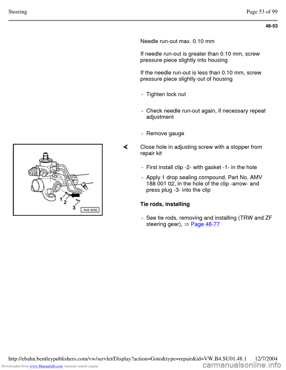
- Remove gauge Close hole in adjusting screw with a stopper from
repair kit
Tie rods, installing - First install clip -2- with gasket -1- in the hole - Apply 1 drop sealing compound, Part No. AMV
188 001 02, in the hole of the clip -arrow- and
press plug -3- into the clip
- See tie rods, removing and installing (TRW and ZF steering gear), Page 48-77 Page 53 of 99Steering12/7/2004http://ebahn.bentleypublishers.com/vw/servlet/Display?action=Goto&type=repair&id=VW.B4.SU01.48.1
Page 339 of 369
Downloaded from www.Manualslib.com manuals search engine 48-69
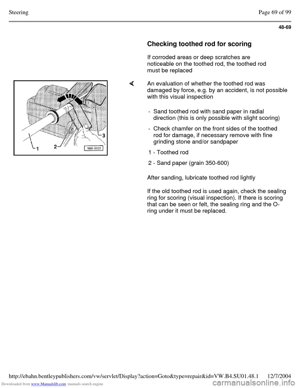
Checking toothed rod for scoring
If corroded areas or deep scratches are
noticeable on the toothed rod, the toothed rod
must be replaced An evaluation of whether the toothed rod was
damaged by force, e.g. by an accident, is not possible
with this visual inspection
After sanding, lubricate toothed rod lightly
If the old toothed rod is used again, check the sealing
ring for scoring (visual inspection). If there is scoring
that can be seen or felt, the sealing ring and the O-
ring under it must be replaced. - Sand toothed rod with sand paper in radial
direction (this is only possible with slight scoring)
- Check chamfer on the front sides of the toothed
rod for damage, if necessary remove with fine
grinding stone and/or sandpaper
1 - Toothed rod 2 - Sand paper (grain 350-600) Page 69 of 99Steering12/7/2004http://ebahn.bentleypublishers.com/vw/servlet/Display?action=Goto&type=repair&id=VW.B4.SU01.48.1