navigation VOLKSWAGEN T-ROC 2018 Owners Manual
[x] Cancel search | Manufacturer: VOLKSWAGEN, Model Year: 2018, Model line: T-ROC, Model: VOLKSWAGEN T-ROC 2018Pages: 502, PDF Size: 8.58 MB
Page 6 of 502

In the engine compartment
Fuse box cover Changing fuses
Lever for adjusting the steering column position Steering wheel
Light switch Vehicle lighting
Turn signal and main beam lever Vehicle lighting
With switches and buttons for the driver assist systems Button for driver assist systemsDriver
assist systems
Vents Heating and air conditioning system
Instrument cluster Instrument cluster
With warning and indicator lamps Symbols in instrument cluster
Lever for wipers and washers Wipers
With buttons for operating the menus Instrument cluster
Controls on the multifunction steering wheel:
Operating driver assist systems Operating using the multifunction steering wheelDriver assist
systems
Audio, navigation
Opening the telephone menu or accepting telephone calls
Volume adjustment
Activating voice control (no function in some models)
Horn
Location of the driver front airbag Airbag system
Ignition lock Starting and stopping the engine
Pedals Pedals
Page 17 of 502

Various, topic-specific information profiles can be selected via the Active Info Display menu option in
the vehicle settings of the Infotainment system Vehicle settings menu
information profile, the Active Info Display shows additional information in the centre of the round
instruments, or the round instruments are hidden and the additional information is displayed across
the whole width of the display. The following information profiles are available:
Gear. Digital display of the current gear or selected position.
Speed. Digital display of the speed.
Consumption. Graphic representation of current consumption and digital display of average
consumption.
Range. Digital display of the remaining range.
Dynamic Road Sign Display. Display of recognised road signs.
Distance travelled. Digital display of the distance covered.
Time of arrival information. Digital display of the remaining driving time, distance to the destination
and estimated time of arrival.
Acceleration. Graphic representation of longitudinal and lateral acceleration.
Assist systems. Graphic representation of various assist systems.
Height. Digital display of the current height above sea level.
Navigation. Graphic representation of arrow navigation.
Compass. Digital compass display.
Audio. Digital display of current audio playback.
The number and functions of the available information profiles can differ depending on the vehicle
equipment.
Navigation map in the Active Info Display
With some vehicle equipment levels, the Active Info Display is able to display a detailed map. To
display this map, select the Navigation menu item in the instrument cluster Instrument cluster
menus
The navigation map can be shown in two sizes. With the larger map size, the navigation map is
displayed over the entire width of the display. To select the preferred map size:
Press the button on the multifunction steering wheel Instrument cluster menusto switch
between map sizes as required.
Page 18 of 502

or arrow button on the multifunction steering wheel to select the required
map size. A frame appears around the selected option.
Press the button on the multifunction steering wheel to confirm your selection.
With some equipment levels, navigation is shown on two screens or only one. The navigation map
can be displayed on the Active Info Display and Infotainment system or only on the Infotainment
system display. In the latter case, only navigation arrows are shown on the Active Info Display.
Displays
First read and observe the introductoryinformation and safety warnings
Possible instrument cluster displays
Open doors, bonnet and boot lid.
Warning and information messages.
Mileage displays.
Time Time
Radio and navigation information ookletInfotainment system,.
Telephone information Infotainment system,.
Outside temperature.
Compass display.
Selector lever positions.
Gear-change indicator Gear-change indicator
Driving data display (multifunction display) and menus for various settings Instrument cluster
menus
Service interval display Service interval display
Speed warning Instrument cluster menus
Speed warning for winter tyres.
Start/stop system status display Start/stop system
Road signs detected by the Dynamic Road Sign Display system Dynamic Road Sign Display (Sign
Assist)
Status display for Active Cylinder Management (ACT
Page 21 of 502

system.
If several warnings are present, the symbols will appear for several seconds, one after another. The
symbols will continue to appear until the faults are rectified.
If warning messages about malfunctions are displayed when the ignition is switched on, it may not
be possible to adjust some settings as described, or the information display may appear differently.
If this is the case, take the vehicle to a qualified workshop to have the malfunctions rectified.
Instrument cluster menus
First read and observe the introductoryinformation and safety warnings
The content and layout of the menus and displays depend on the vehicle electronics and the level of
vehicle equipment.
A qualified workshop can program and modify other functions depending on the vehicle equipment
level. Volkswagen recommends using a Volkswagen dealership for this purpose.
Some menu options can be accessed only when the vehicle is stationary.
Driving dataDriving data di
Assist systems.
Lane Assist on/off Lane keeping system (Lane Assist)
Front Assist on/off Area monitoring system (Front Assist)
Blind Spot Monitor on/off Blind Spot Monitor
ACC (display only) Adaptive Cruise Control (ACC)
Views1)Digital instrument cluster (Active Info Display)
Navigation Infotainment system,.
Audio Infotainment system,.
Telephone Infotainment system,.
Vehicle statusWarning and information messa
Lap timerLap timer
Personalisation (user selection)Personalisation
1) Only in vehicles with an Active Info Display.
Service menu
Page 29 of 502

by trees, snow, dirt or other vehicles.
Road signs that do not correspond to the standard design.
Damaged or bent traffic signs.
Variable road signs on gantries (changeable road sign display using LEDs or other light sources).
Out-of-date map material in the Infotainment system.
Stickers on vehicles that show road signs, e.g. speed restrictions on trucks.
WARNING
The intelligent technology used by the Dynamic Road Sign Display cannot overcome the laws of
physics, and functions only within the limits of the system. Do not let the extra convenience afforded
by the Dynamic Road Sign Display system tempt you into taking any risks when driving. The system is
not a substitute for the full concentration of the driver.
Always adapt your speed and driving style to suit visibility, weather, road and traffic conditions.
Poor visibility, darkness, snow, rain and fog can cause road signs not to be displayed or to be
incorrectly displayed by the system.
If the camera's field of view is dirty, covered or damaged, the function of the Dynamic Road Sign
Display system may be impaired.
WARNING
Driving recommendations and traffic symbols displayed by the Dynamic Road Sign Display system
may differ from the current traffic situation.
Not all road signs can be recognised by the system and displayed correctly.
Road signs on the road and traffic regulations have priority over the recommendations and displays
provided by the Dynamic Road Sign Display system.
NOTICE
Availability of the Dynamic Road Sign Display function is limited in waypoint mode (waypoint
navigation) of the Infotainment system.
Some settings can be saved in the user accounts of the personalisation function and can therefore
change automatically when the user account is changed Personalisation
Page 40 of 502

Introduction
This chapter contains information on the followingsubjects:
Vehicle settings menu
Performance monitor
Lap timer
Personalisat
The Infotainment system combines key vehicle systems in a central operating unit, e.g. menu
settings, radio or navigation system.
General information on operation
The following section contains relevant information on the settings that can be adjusted in the
Vehicle settings menu. Basic information on operating the Infotainment system and on warning and
safety instructions is contained in a separate manual Infotainment system,.
Systems settings and vehicle information display
After pressing the button or touching the function button followed by the Vehicle function
button, touch the corresponding function buttons to display information or make settings. The
current status of systems can be checked or system faults displayed by touching the function
button in the Vehicle status menu.
Vehicle settings (setup) Vehicl
Think Blue. Trainer. Think Blue. Trainer.
Performance monitor Performance monitor
Lap timer Lap timer
Offroad display Offroad driving situations
Auxiliary heater settings Auxiliary heater and ventilation
Active media.
Driving data.
Vehicle status.
Convenience consumers.
Radio station selection.
WARNING
Accidents and injuries can occur if the driver is distracted. Operating the Infotainment system can
distract you from the road.
Page 49 of 502

Is fuel in the adequate quality available Fuel and emission control?
Are the correct service fluids that comply with Volkswagen specifications available in the destination
country Service fluids and consumables?
Will the navigation function in the factory-fitted Infotainment system work with the available
navigation data in the destination country?
Are special tyres necessary for travelling in the destination country?
Is a fire extinguisher a requirement in your destination country?
Which requirements must be observed regarding high-visibility waistcoats?
Checklist
Do not work on the engine and in the engine compartment unless you are familiar with the task, are
aware of the general safety procedures and have the correct equipment, service fluids and suitable
tools In the engine compartment
are uncertain. Make sure you check the following on a regular basis:
Washer fluid level Washer fluid
Engine oil level Engine oil
Coolant level Coolant
Brake fluid level Brake fluid
Tyre pressure Wheels and tyres
Page 73 of 502

anywhere in the airbag deployment zone.
No other people, animals or objects may be carried between the occupants of the front seats and
the airbag deployment zone. Make sure that children and passengers also keep to this rule.
Do not attach any objects, e.g. mobile navigation devices, to the windscreen above the front airbag
on the front passenger side.
Do not cover or stick anything on the steering wheel hub or the soft plastic surface of the airbag unit
on the front passenger side, and do not obstruct or modify them in any way.
WARNING
The front airbags are deployed in front of the steering wheel Fig. 40and dash panelFig. 41
When driving, always hold the steering wheel with both hands on the outside of the rim at the 9
o'clock and 3 o'clock positions.
Adjust the driver seat so that there is at least 25 cm between your breastbone and the hub of the
steering wheel. Contact a qualified workshop if your physical build makes this impracticable.
Adjust the front passenger seat so that the distance between the front passenger and the dash panel
is as large as possible.
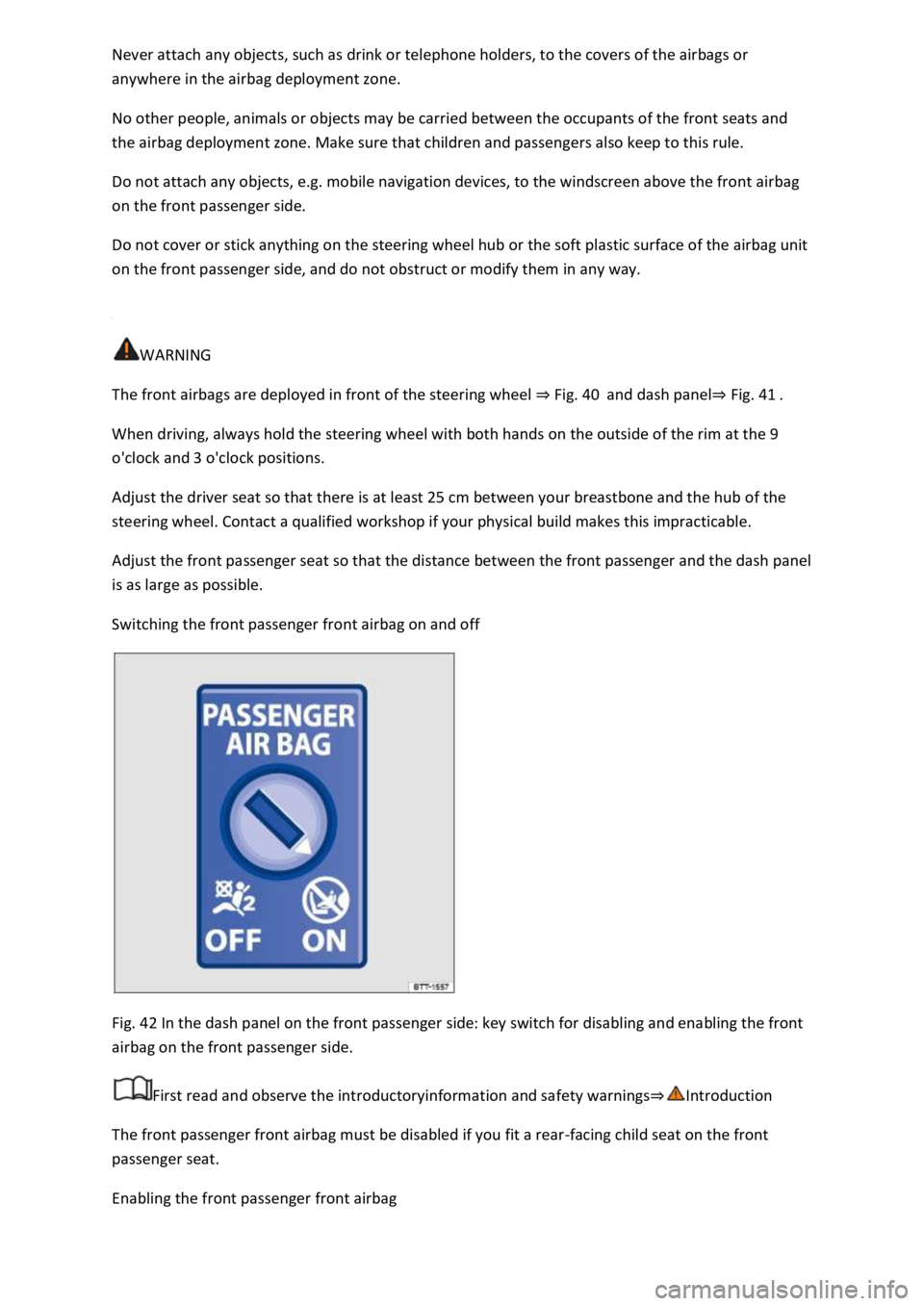
Switching the front passenger front airbag on and off
Fig. 42 In the dash panel on the front passenger side: key switch for disabling and enabling the front
airbag on the front passenger side.
First read and observe the introductoryinformation and safety warnings
The front passenger front airbag must be disabled if you fit a rear-facing child seat on the front
passenger seat.
Enabling the front passenger front airbag
Page 136 of 502

NOTICE
Please observe the following points in order to avoid impairing the proper function of the system:
Regularly clean the camera's field of view, and keep it free from snow and ice.
Do not cover the camera's field of view.
Regularly check the area of the windscreen that is in the camera's field of view for damage.
Light-emitting objects in the camera's field of operation, e.g. mobile navigation devices, can impair
the functions of the main-beam control system.
Parking light
Switching the parking lights on and off
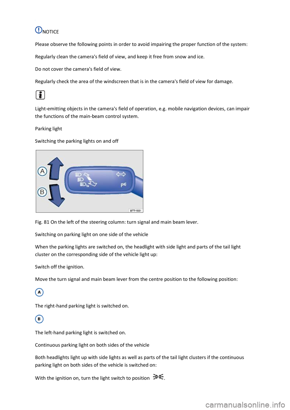
Fig. 81 On the left of the steering column: turn signal and main beam lever.
Switching on parking light on one side of the vehicle
When the parking lights are switched on, the headlight with side light and parts of the tail light
cluster on the corresponding side of the vehicle light up:
Switch off the ignition.
Move the turn signal and main beam lever from the centre position to the following position:
The right-hand parking light is switched on.
The left-hand parking light is switched on.
Continuous parking light on both sides of the vehicle
Both headlights light up with side lights as well as parts of the tail light clusters if the continuous
parking light on both sides of the vehicle is switched on:
With the ignition on, turn the light switch to position .
Page 190 of 502

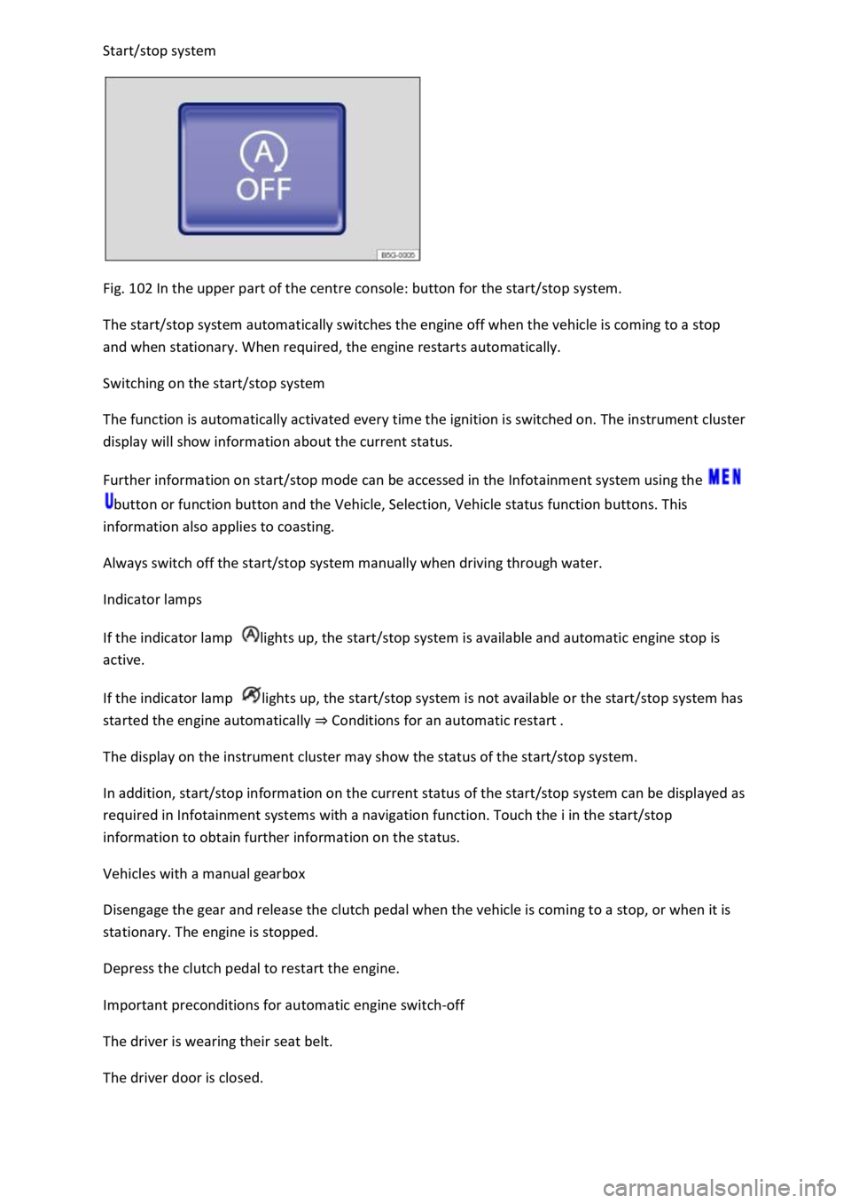
Fig. 102 In the upper part of the centre console: button for the start/stop system.
The start/stop system automatically switches the engine off when the vehicle is coming to a stop
and when stationary. When required, the engine restarts automatically.
Switching on the start/stop system
The function is automatically activated every time the ignition is switched on. The instrument cluster
display will show information about the current status.
Further information on start/stop mode can be accessed in the Infotainment system using the
button or function button and the Vehicle, Selection, Vehicle status function buttons. This
information also applies to coasting.
Always switch off the start/stop system manually when driving through water.
Indicator lamps
If the indicator lamp lights up, the start/stop system is available and automatic engine stop is
active.
If the indicator lamp lights up, the start/stop system is not available or the start/stop system has
started the engine automatically Conditions for an automatic restart
The display on the instrument cluster may show the status of the start/stop system.
In addition, start/stop information on the current status of the start/stop system can be displayed as
required in Infotainment systems with a navigation function. Touch the i in the start/stop
information to obtain further information on the status.
Vehicles with a manual gearbox
Disengage the gear and release the clutch pedal when the vehicle is coming to a stop, or when it is
stationary. The engine is stopped.
Depress the clutch pedal to restart the engine.
Important preconditions for automatic engine switch-off
The driver is wearing their seat belt.
The driver door is closed.