coolant temperature VOLKSWAGEN T-ROC 2020 Owners Manual
[x] Cancel search | Manufacturer: VOLKSWAGEN, Model Year: 2020, Model line: T-ROC, Model: VOLKSWAGEN T-ROC 2020Pages: 502, PDF Size: 8.58 MB
Page 14 of 502

Introduction
This chapter contains information on the followingsubjects:
Analogue instrument cluster
Rev counter
Digital instrument cluster (Active Info Display)
Displays
Instrument cluster menus
Service menu
Driving data display (multifunction display)
Warning and information messages
Driver Alert System (recommendation for rest breaks)
Dynamic Road Sign Display (Sign Assist)
Time
Lap timer
Fuel gauge
Coolant temperature display
Service interval display
The vehicle is equipped either with an analogue or a digital instrument cluster (Active Info Display).
When you start the engine after the 12-volt battery has been totally discharged or changed, you may
find that system settings (time, date, personal convenience settings and programming) have been
changed or deleted. Check and correct the settings as necessary once the 12-volt vehicle battery has
been sufficiently charged.
WARNING
Accidents and injuries can occur if the driver is distracted.
Never press the buttons on the instrument cluster while the vehicle is in motion.
Any settings for the instrument cluster display and displays in the Infotainment system should be
made only when the vehicle is stationary in order to reduce the risk of accidents and serious injuries.
Page 15 of 502

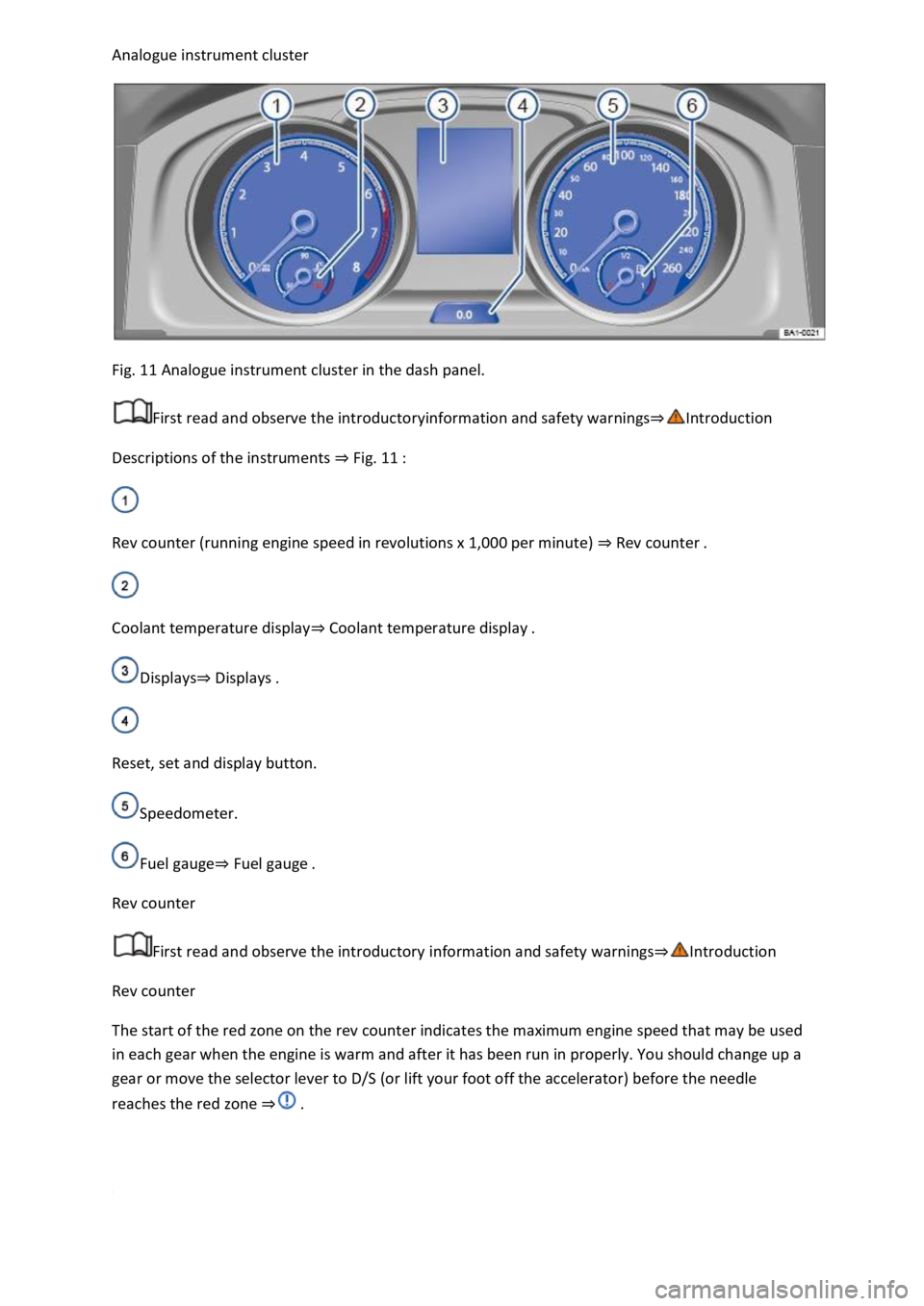
Fig. 11 Analogue instrument cluster in the dash panel.
First read and observe the introductoryinformation and safety warnings
Descriptions of the instruments Fig. 11
Rev counter (running engine speed in revolutions x 1,000 per minute) Rev counter
Coolant temperature displayCoolant temperature display
DisplaysDisplays
Reset, set and display button.
Speedometer.
Fuel gaugeFuel gauge
Rev counter
First read and observe the introductory information and safety warnings
Rev counter
The start of the red zone on the rev counter indicates the maximum engine speed that may be used
in each gear when the engine is warm and after it has been run in properly. You should change up a
gear or move the selector lever to D/S (or lift your foot off the accelerator) before the needle
reaches the red zone
Page 33 of 502

RNING
Driving when the fuel level is too low can lead to the vehicle coming to a standstill in traffic,
potentially causing accidents and serious injuries.
When the fuel level is too low, the fuel supply to the engine could be irregular, especially when
driving up or down hills and inclines.
The steering, all driver assist systems and brake support systems stop working if the engine sputters
or goes off due to fuel shortage or irregular fuel supply.
Always fill the tank when it is still 1/4 full. This reduces the risk of running out of fuel and breaking
down.
NOTICE
Do not run the tank empty. The irregular fuel supply can cause misfiring and allow unburnt fuel to
enter the exhaust system. The catalytic converter or particulate filter could be damaged as a result.
The small arrow next to the petrol pump symbol in the fuel gauge shows you the side of the vehicle
on which the tank flap is located.
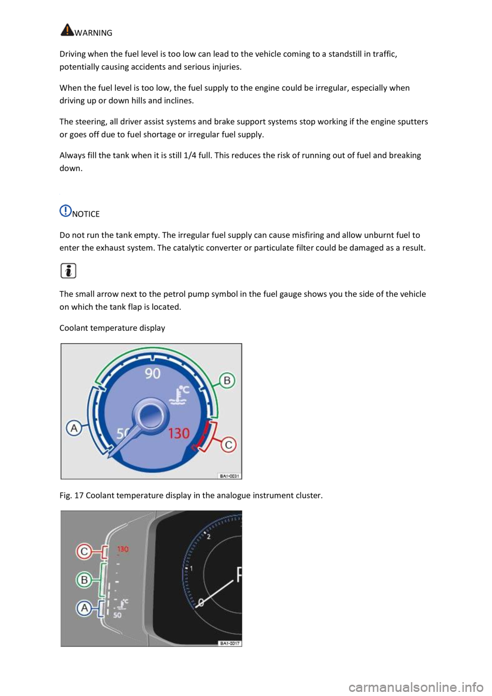
Coolant temperature display
Fig. 17 Coolant temperature display in the analogue instrument cluster.
Page 34 of 502

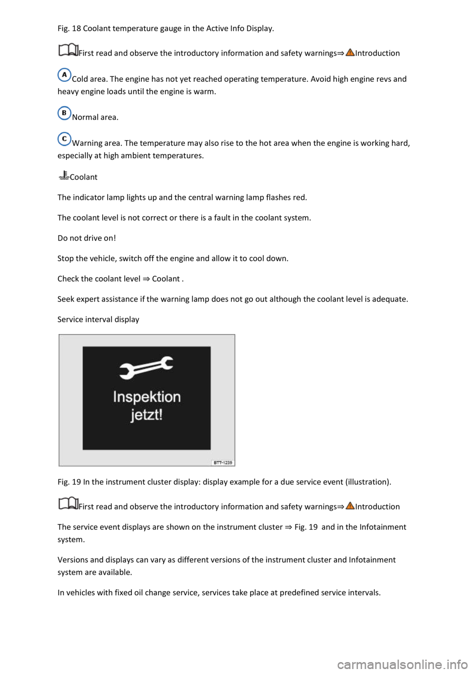
18 Coolant temperature gauge in the Active Info Display.
First read and observe the introductory information and safety warnings
Cold area. The engine has not yet reached operating temperature. Avoid high engine revs and
heavy engine loads until the engine is warm.
Normal area.
Warning area. The temperature may also rise to the hot area when the engine is working hard,
especially at high ambient temperatures.
Coolant
The indicator lamp lights up and the central warning lamp flashes red.
The coolant level is not correct or there is a fault in the coolant system.
Do not drive on!
Stop the vehicle, switch off the engine and allow it to cool down.
Check the coolant level Coolant
Seek expert assistance if the warning lamp does not go out although the coolant level is adequate.
Service interval display
Fig. 19 In the instrument cluster display: display example for a due service event (illustration).
First read and observe the introductory information and safety warnings
The service event displays are shown on the instrument cluster Fig. 19and in the Infotainment
system.
Versions and displays can vary as different versions of the instrument cluster and Infotainment
system are available.
In vehicles with fixed oil change service, services take place at predefined service intervals.
Page 42 of 502

Fig. 23
Display areas.
Arrow buttons for changing to the lap timer.
Opening the performance monitor
Press the MENU button or function button on the Infotainment system.
Touch the Vehicle function button.
Touch the Selection function button.
Touch the Sport function button.
If you would like to switch between the performance monitor and the lap timer Lap timer
one of the arrow buttons on the left and right above the instruments Fig. 23
Selecting instruments and setting units
The display can show a maximum of three instruments at the same time. Each instrument can be
selected for each display area Fig. 23
To change between instruments, swipe vertically over the display. The currently selected instrument
will then disappear and a new instrument will appear.
The units can be adjusted for some instruments in the Infotainment system Vehicle settings
menu
The following instruments can be displayed:
Charge pressure display: the charge pressure display Fig. 23
ar). The further to the right the
needle on the scale, the higher the engine power output.
Accelerometer (G-meter): the accelerometer (G-meter) Fig. 23
-type area shows the
acceleration level and the direction of the acting force (in the opposite direction according to
physical laws). If you drive to the left, for example, the red marking will move in the right area of the
instrument (and vice versa). If you accelerate, the red marking will move down. If you brake, the red
marking will move up. The level of acceleration is indicated by the position of the red marking which
moves outwards. If the acceleration increases, the red marking will move away from the centre area.
Power display: the power display Fig. 23
Coolant temperature display: the needle may move further in a clockwise direction under high
engine loads and with high outside temperatures. This is no cause for concern unless the
indicator lamp in the instrument cluster display is lit up or flashing Coolant temperature display
Oil temperature display: the needle is in the middle area under normal driving conditions. If the
needle is in the bottom left area, this means that the engine has not yet reached its operating
temperature. Avoid excessively high speeds and acceleration when the engine has not yet reached
Page 215 of 502

splay on the instrument
cluster Coolant temperature display
Oil temperature display: the display corresponds with the oil temperature display on the instrument
cluster Engine oil
Adapting the display areas to the driving situation
The displayed instruments can be selected according to the driving situation, the ambient conditions
and the offroad conditions:
Sandy terrain: oil, steering angle and coolant temperature display
Inclines: steering angle and coolant temperature display, altimeter
Alpine terrain: steering angle display, altimeter, compass
Offroad driving situations
Introduction
This chapter contains information on the followingsubjects:
Safety instructions for offroad driving
Explanation of some technical terms
Checklist
General rules and driving tips
Useful accessories for offroad driving
Changing gear correctly
Driving on rough terrain
Driving through water
Offroad driving in snow
Driving on sand an
Driving on steep terrain
Traversing a slope
Driving through ditches
Stuck vehicle
After offroad driving
You can also drive vehicles with all-wheel drive offroad in addition to on normal roads. It is very
important to read the contents of this section before driving offroad.
The vehicle is not built for expedition-type journeys.
Page 363 of 502

expansion tank when the engine is hot. Coolant may spray out and cause serious burns and other
injuries.
-clockwise while exerting
gentle downward pressure on the cap.
face, hands and arms from hot coolant or steam with a large, thick cloth.
spilt service fluids can start a fire.
WARNING
High voltages in the electrical system can cause electric shocks, burns, serious injuries and death!
-volt battery could explode.
started, never touch the electrical cables in the ignition system.
WARNING
There are rotating components in the engine compartment that can cause serious injury.
rotor blades can result in serious injuries. The fan is temperature-controlled and can start
automatically, even when the ignition has been switched off or the vehicle key has been removed
from the ignition lock.
e engine is started or with the engine running, there is an
additional, potentially fatal safety risk from the rotating parts, such as the poly V-belt, alternator,
radiator fan, and from the high-voltage ignition system. Always be particularly careful.
Always ensure that no body parts, jewellery, ties, loose items of clothing or long hair can be
caught up in rotating engine components. Before starting work, remove any jewellery and ties, tie
up long hair and pull clothes in tightly to avoid them getting caught on engine parts.
could move, even if the electronic parking brake is applied.
s and tools, in the engine
compartment. Any forgotten items can cause malfunctions, engine damage and fires.
WARNING
Page 369 of 502

original containers as
people finding these containers could drink them.
es.
-ventilated
area.
r or other volatile fluids for vehicle care.
These substances are toxic and highly flammable. They could cause fires and explosions.
NOTICE
this can result in serious malfunctions and engine damage.
-on parts in front of the air intake reduce the cooling effect of the
coolant. The engine may overheat at high ambient temperatures and high engine loads.
Leaking service fluids can pollute the environment. Spilt service fluids must be collected in suitable
containers and disposed of properly and with respect for the environment.
Washer fluid
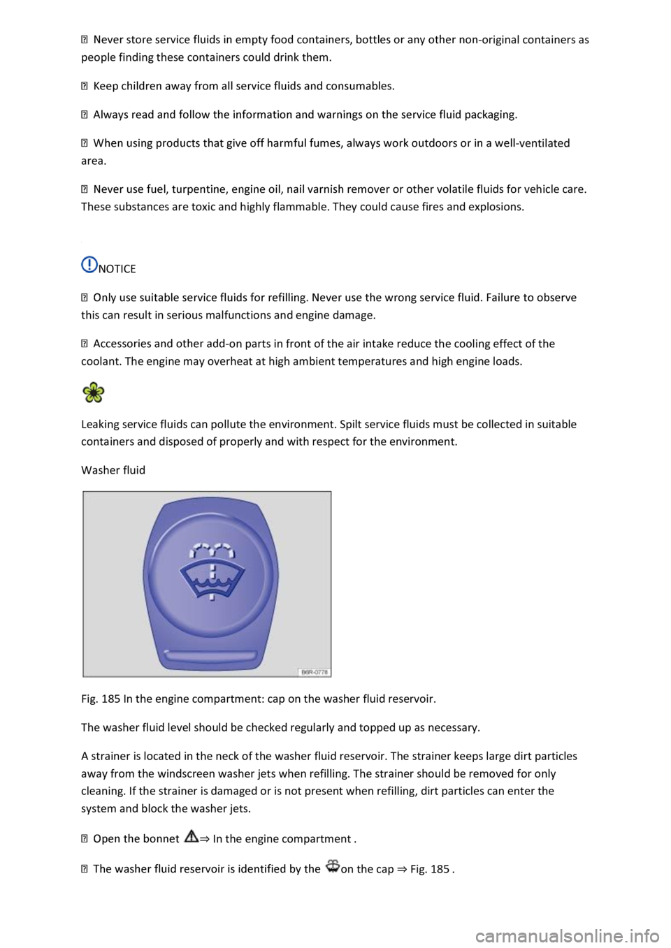
Fig. 185 In the engine compartment: cap on the washer fluid reservoir.
The washer fluid level should be checked regularly and topped up as necessary.
A strainer is located in the neck of the washer fluid reservoir. The strainer keeps large dirt particles
away from the windscreen washer jets when refilling. The strainer should be removed for only
cleaning. If the strainer is damaged or is not present when refilling, dirt particles can enter the
system and block the washer jets.
In the engine compartment
on the cap Fig. 185
Page 378 of 502

Introduction
This chapter contains information on the followingsubjects:
Coolant specification
Checking the coolant level and refilling coolant
Do not work on the cooling system unless you are familiar with the task, aware of the general safety
procedures and have the correct equipment, service fluids and suitable tools. Serious injuries can be
caused by carrying out work incorrectly
workshop if you are uncertain. Volkswagen recommends using a Volkswagen dealership for this
purpose.
WARNING
Coolant is toxic.
ce.
-original containers as
people finding these containers may then drink the coolant.
ct coolant additive used must be sufficient for the lowest
ambient temperature that you expect the vehicle to be exposed to.
Vehicle occupants with inadequate winter clothing could then freeze to death as the heating will
also no longer function.
Coolant and coolant additives can pollute the environment. Spilt service fluids must be collected
then disposed of properly and in an environmentally responsible way.
Coolant specification
First read and observe the introductoryinformation and safety warnings
The cooling system is filled at the factory with a mixture of specially prepared water and at least 40%
coolant additive G 13 (TL-VW 774 J).
The proportion of engine coolant additive must always be at least 40% to protect the cooling system.
If greater frost protection is required in very cold climates, the proportion of anti-freeze additive can
be increased. However, the percentage of coolant additive should not exceed 60%, as this would
reduce the frost protection again and the cooling effect.