AUX VOLKSWAGEN TRANSPORTER 2011 User Guide
[x] Cancel search | Manufacturer: VOLKSWAGEN, Model Year: 2011, Model line: TRANSPORTER, Model: VOLKSWAGEN TRANSPORTER 2011Pages: 486, PDF Size: 69.28 MB
Page 310 of 486
Volkswagen recommends that Front Assist is switched on at all times. Exceptions =>page 310, Temporarily switch off the front scan system (Front Assist) in the following situations.
Activating and deactivating the front scan system
The front scan system can be activated and deacti-vated using the Front Assist option in the As-sistant submenu of the Settings menu. A tick indicates that a driver assist system is switched on.
The advance warning and distance warning are deactivated as well when the front scan system is deactivated.
If the front scan system is deactivated, a confirma-tory symbol is shown in the instrument cluster dis-play =>page 308
Activating and deactivating the advanced warning
The advance warning can be activated and deacti-vated using the Front Assist option in the As-sistant submenu of the Settings menu.
Activating or deactivating the distance warning
Depending on the vehicle equipment, the distance warning can be activated and deactivated using the Front Assist option in the Assistant sub-menu of the Settings menu.
Volkswagen recommends that the distance warn-ing is switched on at all times.
following situations
r-T'n First read and observe the introductory l-J,::JJ information and safety warnings & on page 307.
The area monitoring system (Front Assist) should be switched off in the following situations due to system limitations => &:
• If the vehicle is being towed.
• If the vehicle is on a rolling road test bed.
• If the vehide is utilised in a capacity beyond us-age on public roads, e.g. off-road or racing.
• If the radar sensor is faulty.
310 I While drivtng
• On external force on the radar sensor, e.g. after a rear-end collision.
• In the event of multiple unwanted interventions.
• If the radar sensor is covered temporarily by any auxiliary equipment, e.g. auxiliary headlights.
• If the vehicle is being loaded onto a truck, car ferry or motorail train.
A WARNING
Failure to switch off Front Assist in the situa-tions mentioned can cause accidents and se-rious Injuries.
Page 322 of 486
Air conditioning system
Heating, ventilating, cooling
o:n Introduction
This chapter contains information on the following subjects:
Controls for Climatic . . . . . . . . . . . . . . . . . . . . 323
Controls for Climatronic . . . . . . . . . . . . . . . . . 325
Controls for the heating and fresh air system . 327
Information on the air conditioning system . . . 328
..................... m
Air recirculation mode . . . . . . . • . . . . . . . . . . . . 330
Windscreen heating . . . . . . . . . . . . . . . . . . . . . 331
Roof ventilator . . . . . . . . . . . . . . . . . . . . . . . . . . 331
Displays for the Climatronic information
Depending on the vehicle equipment level, infor-mation on the Climatronic is displayed briefly on the screen of the factory-fitted radio or navigation system.
The dust and pollen filter
The dust and pollen filter with activated charcoal reduces the level of impurities in the outside air en-tering the vehicle.
The dust and pollen filler must be changed regular-ly to avoid impairing the performance of the air conditioning system.
The dust and pollen filter must be changed more frequently than stated in the service schedule if the efficiency of the filter declines prematurely due to the vehicle being used in areas with high levels of air pollution.
Additional information and warnings:
• Exterior views 5
• Wipers/washer 116
• Supplementary heaters (auxiliary air heater or auxiliary coolant heater) 332
• Cleaning and caring for the vehicle exterior 380
A WARNING
Poor visibility through all windows increases the risk of collisions and accidents, which can cause serious injuries.
• Always ensure that all windows are free of ice, snow and mist to ensure good visibility.
3221 While driving
A WARNING (Continued)
• Maximum heat output, which Is needed to defrost the windows as quickly as possible, is only available when the engine has reached Its operating temperature. Do not start your journey until you have good visibil-Ity.
• Always ensure that the heating and fresh air system or the air conditioning system and the rear window heating are used correctly so that you have good visibility.
• Never use the air reclrculatlon mode for an extended period. If the cooling system Is switched off, the windows can mist up very quickly In air reclrculatlon mode and reduce visibility considerably.
• Always switch off the air reclrculatlon mode when it Is not required.
A WARNING
Stale air can quickly make the driver tired and affect their concentration, which In turn can cause collisions, accidents and serious Inju-ries.
• Never switch off the blowers or switch on the air recirculatlon mode for an extended pe· riod as this prevents fresh air from entering the vehicle interior.
• Repairs to the air conditioning system re-quire specialist knowledge and special tools. Volkswagen Commercial Vehicles recommends using a Volkswagen Commercial Vehicles deal-ership for this purpose.
Page 332 of 486
![VOLKSWAGEN TRANSPORTER 2011 User Guide Supplementary heaters (auxiliary air heater or auxiliary
coolant heater)
[Q] Introduction
This chapter contains information on the following subjects:
Controls . . . . . . . . . . . . . . . . . . VOLKSWAGEN TRANSPORTER 2011 User Guide Supplementary heaters (auxiliary air heater or auxiliary
coolant heater)
[Q] Introduction
This chapter contains information on the following subjects:
Controls . . . . . . . . . . . . . . . . . .](/img/18/55786/w960_55786-331.png)
Supplementary heaters (auxiliary air heater or auxiliary
coolant heater)
[Q] Introduction
This chapter contains information on the following subjects:
Controls . . . . . . . . . . . . . . . . . . . . . . . . . . . . . . . 333
Switching the supplementary heating system on and off . . . . . . . . . . . . . . . . . . . . . . . . 334
Remote control . . . . . . . . . . . . . . . . . 335
Programming the supplementary heating system . . . . . . . . . . . . . . . . . . . . . . 338 Switching the child proof lock on and off . . . . . 339
Operation . . . . . . . . . . . . . . . . . . . . . . . . 339
The supplementary heating system is supplied with fuel from the vehicle fuel tank and can be used when the vehicle is in motion or stationary. Electri-cal power is supplied by the vehicle battery.
The auxiliary air heater runs in air recirculation mode and heats the vehicle interior. it has sepa-rate vents in the passenger compartment =>Fig. 265.
The auxiliary coolant heater heats the heating circuit. Heat is guided into the vehicle interior via the vents for the heating or air conditioning system. With the auxiliary coolant heater, it is possible to switch between heating and ventilating.
Additional information and warnings:
• Supplementary heater in the California =>page 192
• Filling the tank =>page 340
• Battery =>page 362
Swallowing batteries with a diameter of 20 mm or other lithium batteries can result in severe or even fatal injuries within a very short period of time.
• Always keep the vehicle key, key ring with batteries, spare batteries, round cells and other batteries that are larger than 20 mm out of the reach of children.
332 I While driving
• Call for medical help immediately you pect that someone has swallowed a batte
A WARNING
The fumes from the supplementary heating system contain carbon monoxide, which is an odourless and colourless poisonous gas. Carbon monoxide can cause people to lose consciousness. lt can also cause death.
• Never start or run the supplementary heat-ing system In unventllated or closed rooms.
• Never program the supplementary heating system so that Is switched on and run In un-ventilated or enclosed areas.
A WARNING
Parts of the exhaust system of the supple-mentary heating system become very hot. This can cause fires.
• Park the vehicle so that no part of the ex-haust system can come Into contact with any Inflammable material underneath the vehicle, e.g. dry grass.
Q)
Do not place any food, medicine or any other temperature-sensitive items in front of the vents. Heat-sensitive food, medicine and other items could be either damaged or rendered useless.
m After starting the engine with a discharged W vehicle battery, or after the battery has been changed, system settings (time, date, personal convenience settings and programming) may have been changed or deleted. Check and correct the settings as necessary once the vehicle battery has been sufficiently charged.
Page 333 of 486
Controls
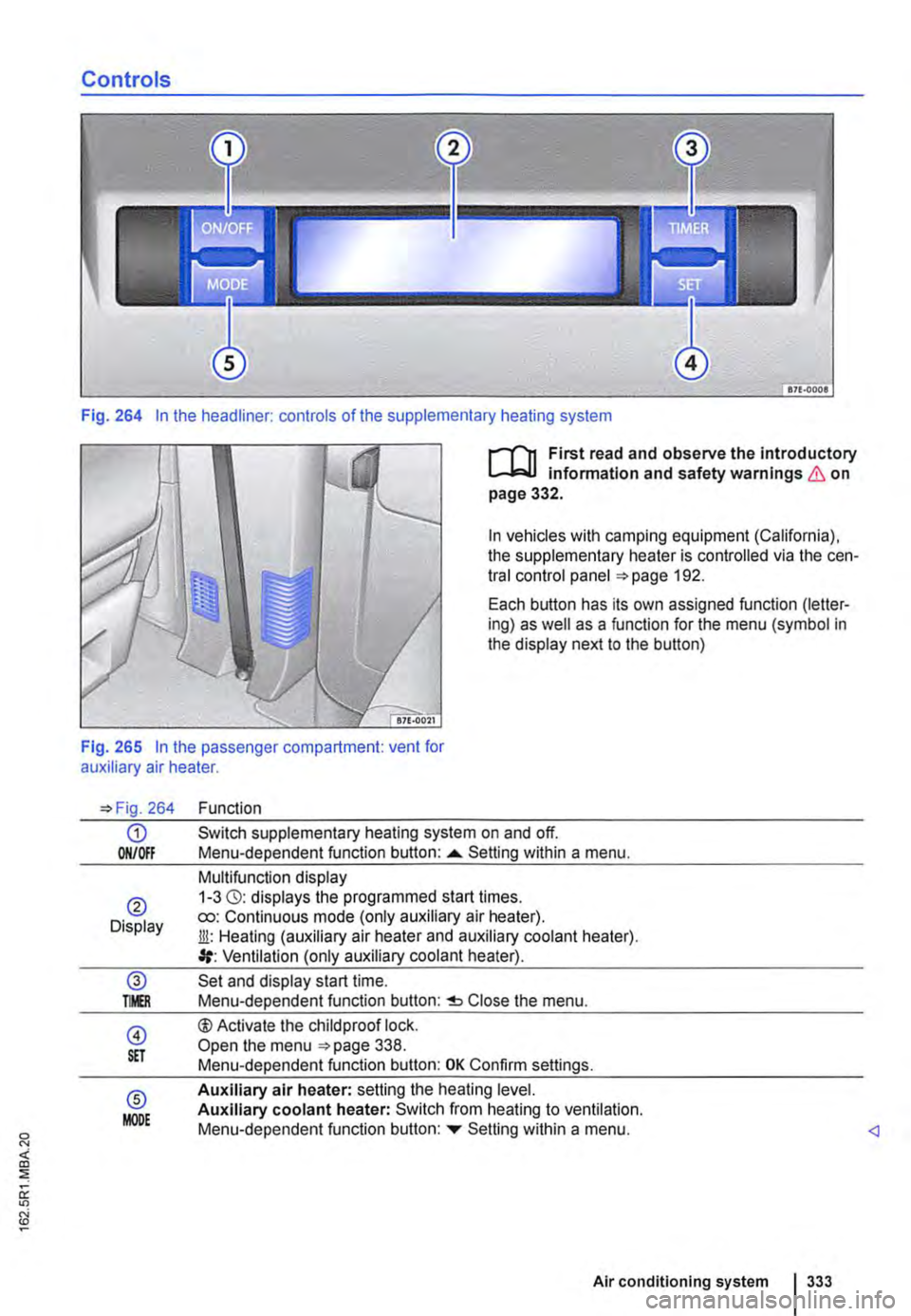
Fig. 264 In the headliner: controls of the supplementary heating system
I""""T'n First read and observe the introductory l.-..1=.1.1 infonmatlon and safety warnings & on page 332.
In vehicles with camping equipment (California), the supplementary heater is controlled via the cen-tral control panel 192.
Each button has its own assigned function (letter-ing) as well as a function for the menu (symbol in the display next to the button)
Fig. 265 In the passenger compartment: vent for auxiliary air heater.
264
G) ON/Off
® Display
@ TMR
@ S£T
® MODE
Function
Switch supplementary heating system on and off. Menu-dependent function button: ......_ Setting within a menu.
Multifunction display 1-3 (3): displays the programmed start times. ro: Continuous mode (only auxiliary air heater). Jli: Heating (auxiliary air heater and auxiliary coolant heater). Ventilation (only auxiliary coolant heater).
Set and display start time. Menu-dependent function button: Close the menu.
®Activate the child proof lock. Open the menu 338. Menu-dependent function button: OK Confirm settings.
Auxiliary air heater: setting the heating level. Auxiliary coolant heater: Switch from heating to ventilation. Menu-dependent function button: ...,. Setting within a menu.
Air conditioning system I 333
Page 334 of 486
Switching the supplementary heating system on and off
r-Y'n First read and observe the introductory L-J.:.I.I information and safety warnings & on page 332.
In vehicles with camping equipment (California), the supplementary heater is controlled via the cen-tral control panel =>page 192.
Switching on the supplementary heating sys-tem:
Manually with button [011/0IF) in the roof dis-ON/OFF play.
l/i Manually with the remote control key.
Automatically with a programmed and ac-tivated switch-on time.
Switching off the supplementary heating sys-tem:
ON/OFF Manually with the function button =>Fig. 264 CD in the roof display.
Off Manually with the remote control key.
Automatically after the set operating dura-tion has elapsed.
Only if the vehicle has an auxiliary coolant heater Automatically when the indicator lamp lights (fuel gauge) =>page 340.
Automatically if the charge level of the ad-ditional battery is too low =>page 362.
Setting the operating duration (when the ignition is switched off)
The default setting for the operating duration is 30 minutes. You can set the operating duration be-tween 10 and 120 minutes.
• Press any button on the roof display to activate the roof display.
• Only if the vehicle has an auxiliary coolant heater: Press the button to set the operating mode.
• Press the@ button.
• Press the button@) to set the operating dura-tion.
334 I While driv1ng
• Press the function button ....,. or T until the re-quired operating duration is displayed.
• Press button@) again to confirm the operating duration.
• Only for auxiliary air heater: press the func-tion button ....,. or ... as often as necessary until the desired heating level is displayed.
The supplementary heating system has been switched on. The operatin_lLduration is counted backwards. Press to switch off the sup-plementary heating system prematurely.
Continuous mode eo (only for auxiliary air heater, with the ignition switched off)
Press any button on the roof display to activate the roof display.
Press the@) button.
Press the @) button.
Press the function button ....,. or ... as often as nec-essary until Heating eo is displayed.
Press button @)to confirm the setting.
Press the function button ....,. or T as often as nec-essary until the required temperature level is dis-played.
Press button @)again to confirm the temperature.
Things to note
The supplementary heating system runs on for a short time after it is switched off in order to cool the heating unit (switch-off delay). The exhaust gases in the system can also be emitted.
Switch-off delay for the auxiliary heater
If the ignition is switched off while the auxiliary wa-ter heater is on, the selected function continues being performed for a maximum of 10 minutes. The set switch-off delay is shown on the display.
Each time button is pressed, the switch-off delay is reduced by one minute.
Page 335 of 486
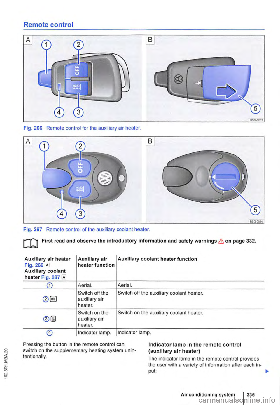
Remote control
B
BSG·OOS3
Fig. 266 Remote control for the auxiliary air heater.
A
BSG-0054
Fig. 267 Remote control of the auxiliary coolant heater.
ru First read and observe the introductory Information and safety warnings & on page 332.
Auxiliary air heater Auxiliary air Auxiliary coolant heater function Fig. heater function Auxiliary coolant heater Fig. 267
CD Aerial. Aerial.
Switch off the Switch off the auxiliary coolant heater.
0@) auxiliary air heater.
Switch on the Switch on the auxiliary coolant heater.
0@ auxiliary air heater.
@) Indicator lamp. Indicator lamp.
Pressing the button in the remote control can switch on the supplementary heating system unin-tentionally.
Indicator lamp in the remote control (auxiliary air heater)
The indicator lamp in the remote control provides the user with a variety of information after each in-put: 1>-
Air conditioning system 335
Page 336 of 486
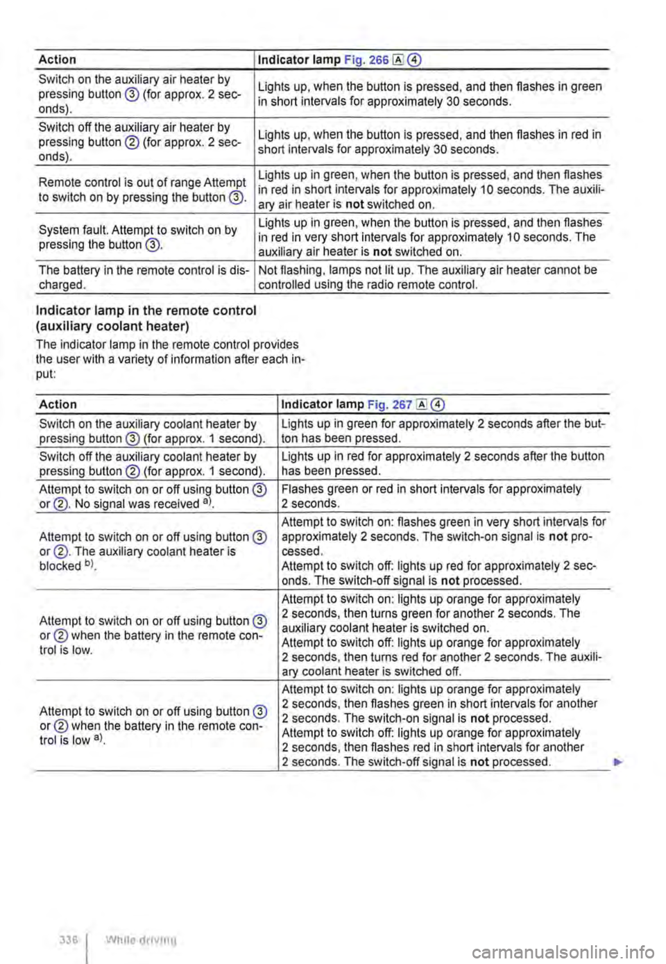
Action I Indicator lamp Fig. 266
Switch on the auxiliary air heater by pressing button @ (for approx. 2 sec-onds).
Switch off the auxiliary air heater by pressing button ® (for approx. 2 sec-onds).
Lights up, when the button is pressed, and then flashes in green in short intervals for approximately 30 seconds.
Lights up, when the button is pressed, and then flashes in red in short intervals for approximately 30 seconds.
Lights up in green, when the button is pressed, and then flashes Remote control is out of range Attempt in red in short intervals for approximately 10 seconds. The auxili-to switch on by pressing the button @. ary air heater is not switched on.
System fault. Attempt to switch on by pressing the button @.
Lights up in green, when the button is pressed, and then flashes in red in very short intervals for approximately 10 seconds. The auxiliary air heater is not switched on.
The battery in the remote control is dis-charged. Not flashing, lamps not lit up. The auxiliary air heater cannot be controlled using the radio remote control.
Indicator lamp in the remote control (auxiliary coolant heater)
The indicator lamp in the remote control provides the user with a variety of information after each in-put:
Action Indicator lamp Fig. 267
Switch on the auxiliary coolant heater by Lights up in green for approximately 2 seconds after the but-pressing button@ (for approx. 1 second). ton has been pressed.
Switch off the auxiliary coolant heater by Lights up in red for approximately 2 seconds after the button pressing button® (for approx. 1 second). has been pressed.
Attempt to switch on or off using button @ Flashes green or red in short intervals for approximately or@. No signal was received a). 2 seconds.
Attempt to switch on: flashes green in very short intervals for Attempt to switch on or off using button@ approximately 2 seconds. The switch-on signal is not pro-or@. The auxiliary coolant heater is cessed. blocked b). Attempt to switch off: lights up red for approximately 2 sec-onds. The switch-off signal is not processed.
Attempt to switch on: lights up orange for approximately
Attempt to switch on or off using button@ 2 seconds, then turns green for another 2 seconds. The
or® when the battery in the remote con-auxiliary coolant heater is switched on. Attempt to switch off: lights up orange for approximately trot is low. 2 seconds, then turns red for another 2 seconds. The auxili-ary coolant heater is switched off.
Attempt to switch on: lights up orange for approximately
Attempt to switch on or off using button @ 2 seconds, then flashes green in short intervals for another
or® when the battery in the remote con-2 seconds. The switch-on signal is not processed.
trot is low a). Attempt to switch off: lights up orange for approximately 2 seconds, then flashes red in short intervals for another 2 seconds. The switch-off signal is not processed.
336 I While droving
Page 337 of 486
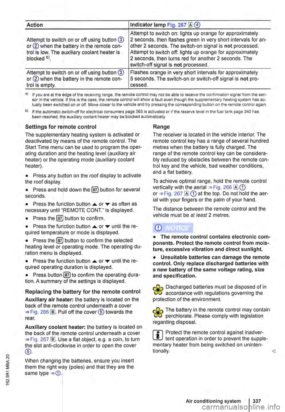
Action Indicator lamp Fig. 267
Attempt to switch on: lights up orange for approximately Attempt to switch on or off using button @ or@ when the battery in the remote con-trol is low. The auxiliary coolant heater is blocked bl.
2 seconds, then flashes green in very short intervals for an-other 2 seconds. The switch-on signal is not processed. Attempt to switch off: lights up orange for approximately 2 seconds, then turns red for another 2 seconds. The switch-off signal is not processed.
Attempt to switch on or off using button @ or@ when the battery in the remote con-trol is empty.
Flashes orange in very short intervals for approximately 5 seconds. The switch-on or switch-off signal is not pro-cessed.
•> If you are at the edge of the receiving range, the remote control may not be able to receive the confirmation signal from the sen-sor in the vehicle. If this is the case, the remote control will show a fault even though the supplementary heating system has ac-tually been switched on or off. Move closer to the vehicle and try pressing the corresponding button on the remote control again.
b) If the automatic switch-off for electrical consumers page 365 is activated or if the reserve level in lhe fuel tank page 340 has been reached, the auxiliary coolant heater may be blocked automatically.
Settings for remote control
The supplementary heating system is activated or deactivated by means of the remote control. The Start Time menu can be used to program the oper-ating duration and the heating level (auxiliary air heater) or the operating mode (auxiliary coolant heater).
• Press any button on the roof display to activate the roof display.
• Press and hold down the (ill) button for several seconds.
• Press the function button ...... or ,... as often as necessary until "REMOTE CONT." is displayed.
• Press the (ill) button to confirm.
• Press the function button ...... or ,... until the re-quired temperature or mode is displayed.
• Press the (ill) button to confirm the selected heating level or operating mode. The operating du-ration menu is displayed.
• Press the function button ...... or ,... until the re-quired operating duration is displayed.
• Press button @)to confirm the operating dura-tion. A summary of the settings is displayed.
Replacing the battery for the remote control
Auxiliary air heater: the battery is located on the back of the remote control underneath a cover 266 [ID. Pull off the cover® towards the rear.
Auxiliary coolant heater: the battery is located on the back of the remote control underneath a cover 267 [ID. Use a flat object, e.g. a coin, to turn the slot anti-clockwise in order to open the cover
®-
When changing the batteries, ensure you insert them the right way (poles) and that they are the same type
Range
The receiver is located in the vehicle interior. The remote control key has a range of several hundred metres when the battery is fully charged. The range of the remote control key can be considera-bly reduced by obstacles between the remote con-trol key and the vehicle, bad weather conditions, and a flat battery.
To achieve optimal range, hold the remote control vertically with the aerial 266 or 267 at the top. Do not hold the aer-ial with your fingers or the palm of your hand.
The distance between the remote control and the vehicle must be at least 2 metres.
CD
• The remote control contains electronic com-ponents. Protect the remote control from mois-ture, excessive vibration and direct sunlight.
• Unsuitable batteries can damage the remote control. Only replace discharged batteries with a new battery of the same voltage rating, size and specification.
Discharged batteries must be disposed of in W accordance with regulations governing the protection of the environment.
The battery in the remote control may contain W perchlorate. Please comply with legislation regarding disposal.
m Protect the remote control against inadver-L!.J tent operation in order to prevent the supple-mentary heater from being switched on uninten-
Air conditioning system I 337
Page 365 of 486
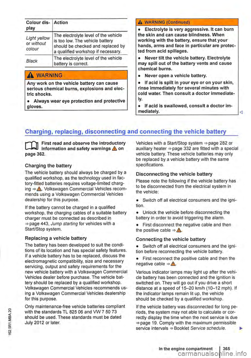
Colour dis-Action play
Light yellow The electrolyte level of the vehicle
or without is too low. The vehicle battery
colour should be checked and replaced by a qualified workshop if necessary.
Black The electrolyte level of the vehicle battery is correct.
A WARNING
Any work on the vehicle battery can cause serious chemical burns, explosions and elec-trlc shocks.
• Always wear eye protection and protective gloves.
A WARNING (Continued)
• Electrolyte is very aggressive. lt can burn the skin and can cause blindness. When working with the battery, ensure that your hands, arms and face in particular are protec-ted from acid spillages.
• Never tilt the vehicle battery. Electrolyte may spill out of the battery vents and cause chemical burns.
• Never open a vehicle battery.
• if acid is spilt in your eye or on your skin, rinse immediately for several minutes with cold water. Then consult a doctor immediate-ly.
• If acid is swallowed, consult a doctor im-mediately.
r-"f'n First read and observe the introductory L-Jo:.l.l information and safety warnings & on page 362.
Charging the battery
The vehicle battery should always be charged by a qualified workshop, as the technology used in fac-tory-fitted batteries requires voltage-limited charg-ing => &. Volkswagen Commercial Vehicles recom-mends using a Volkswagen Commercial Vehicles dealership for this purpose.
If the battery cannot be charged in a qualified workshop, the charging cables of a suitable battery charger must be connected as described in =>page 443, Jump starting for vehicles with a Start/Stop system.
Replacing a vehicle battery
The battery has been developed to suit the condi-tions of its location and has special safety features. If a vehicle battery has to be replaced, discuss the electromagnetic compatibility, size and necessary servicing, output and safety requirements for the new vehicle battery with a Volkswagen Commercial Vehicles dealer before purchase. The vehicle bat-tery should be replaced by a qualified workshop. Volkswagen Commercial Vehicles recommends us-ing a Volkswagen Commercial Vehicles dealership for this purpose.
Only maintenance-free vehicle batteries compliant with the standards TL 825 06 and VVV 7 50 73 should be used. These standards must be dated July 2012 or later.
Vehicles with a Start/Stop system =>page 282 or auxiliary heater =>page 332 are fitted with a special vehicle battery. These vehicle batteries may only be replaced by a vehicle battery with the same specifications.
Disconnecting the vehicle battery
Please note the following if the vehicle battery has to be disconnected from the electrical system in the vehicle:
• Switch off all electrical consumers and the igni-tion.
• Unlock the vehicle before disconnecting the battery in order to avoid triggering the alarm.
• First disconnect the negative cable and then the positive cable => &.
Connecting the vehicle battery
• Switch off all electrical consumers and the igni-tion before reconnecting the vehicle battery.
• First reconnect the positive cable and then the negative cable=>&.
Various indicator lamps may light up after the vehi-cle battery has been connected and the ignition is switched on. They will go out if you drive a short distance at a speed of 15-20 kmlh (10-12 mph). If the indicator lamps remain lit up, the vehicle should be checked by a qualified workshop.
if the vehicle battery was disconnected for long pe-riods, the system may not able to calculate or cor-rectly display the time when the next service is due =>page 19. Comply with the maximum permissible service intervals =>Booklet Service schedule. ""
In the engine compartment 365
Page 396 of 486
should be replaced at a qualified workshop. Volks-wagen Commercial Vehicles dealers are kept up to date with regard to any changes.
A WARNING
Unsuitable service fluids and consumables, and the Incorrect use of these fluids and con-sumables, can cause accidents, serious inju-ries, burns or poisoning.
• Service fluids must be kept In their origi-nal sealed container.
• Never store service fluids In empty food containers, bottles or any other non-original containers as people finding these containers could drink them.
• Keep children away from all service fluids and consumables.
• Always read and follow the Information and warnings on the service fluid packaging.
Repairs and technical modifications
.....-T'n First read and observe the Introductory l-J,::JJ Information and safety warnings & on page 394.
Repairs and modifications must always be car-ried out according to Volkswagen Commercial Vehicles specifications =:ob:,!
Unauthorised modifications to the electronic com-ponents or software in the vehicle may cause faults. As the electronic components are linked to-gether in networks. other systems may be affected by the faults. This can seriously impair safety, lead to excessive wear of components, and also invalid-ate the type approval for the vehicle.
The Volkswagen Commercial Vehicles dealer can-not be held liable for any damage caused by tech-nical modifications and/or work performed incor-rectly.
The Volkswagen Commercial Vehicles dealer can-not be held liable for any damage caused by tech-nical modifications and/or work performed incor-rectly. This is also not covered by the Volkswagen guarantee.
3961 Clt!aning and maintenance
A WARNING (Continued)
• When using products that give off harmful fumes, always work outdoors or In a well-ventilated area.
• Never use fuel, turpentine, engine oil, nail varnish remover or other volatile fluids for vehicle care. They are toxic and highly flam-mable. They could cause fires and explo-sions.
CD
• Only use suitable service fluids for refilling. Never use the wrong service fluid. Failure to observe this warning can result In serious mal-functions and engine damage.
• Optional equipment and other accessories In front of the air Inlet reduce the cooling effect of the coolant. The engine may overheat at high ambient temperatures and high engine loads.
Leaking service fluids can pollute the envi-C!IS ronment. Spilt service fluids must be collec-ted in suitable containers and disposed of properly and with respect for the environment.
Vehicles with special auxiliary equipment or body parts
The manufacturer of these components must en-sure that these parts (fittings) adhere to the stipula-ted environmental laws and regulations, particular-ly the EU directive 2000/53/EC concerning end-of-life vehicles and EU directive 2003/11/EC concern-ing the restriction on the marketing and use of cer-tain dangerous substances and preparations.
The vehicle owner should keep all assembly docu-mentation for these auxiliary fittings, and pass it on to any scrapping company later engaged. This is to facilitate environmentally responsible disposal for all vehicles, Including refitted vehicles.
Windscreen repairs
To function properly, some items of equipment re-quire a camera or sensor, which Is located on the inside of the windscreen near the interior mirror. If the windscreen in the viewing field of the camera ,..