change time VOLKSWAGEN TRANSPORTER 2011 Owner's Manual
[x] Cancel search | Manufacturer: VOLKSWAGEN, Model Year: 2011, Model line: TRANSPORTER, Model: VOLKSWAGEN TRANSPORTER 2011Pages: 486, PDF Size: 69.28 MB
Page 207 of 486
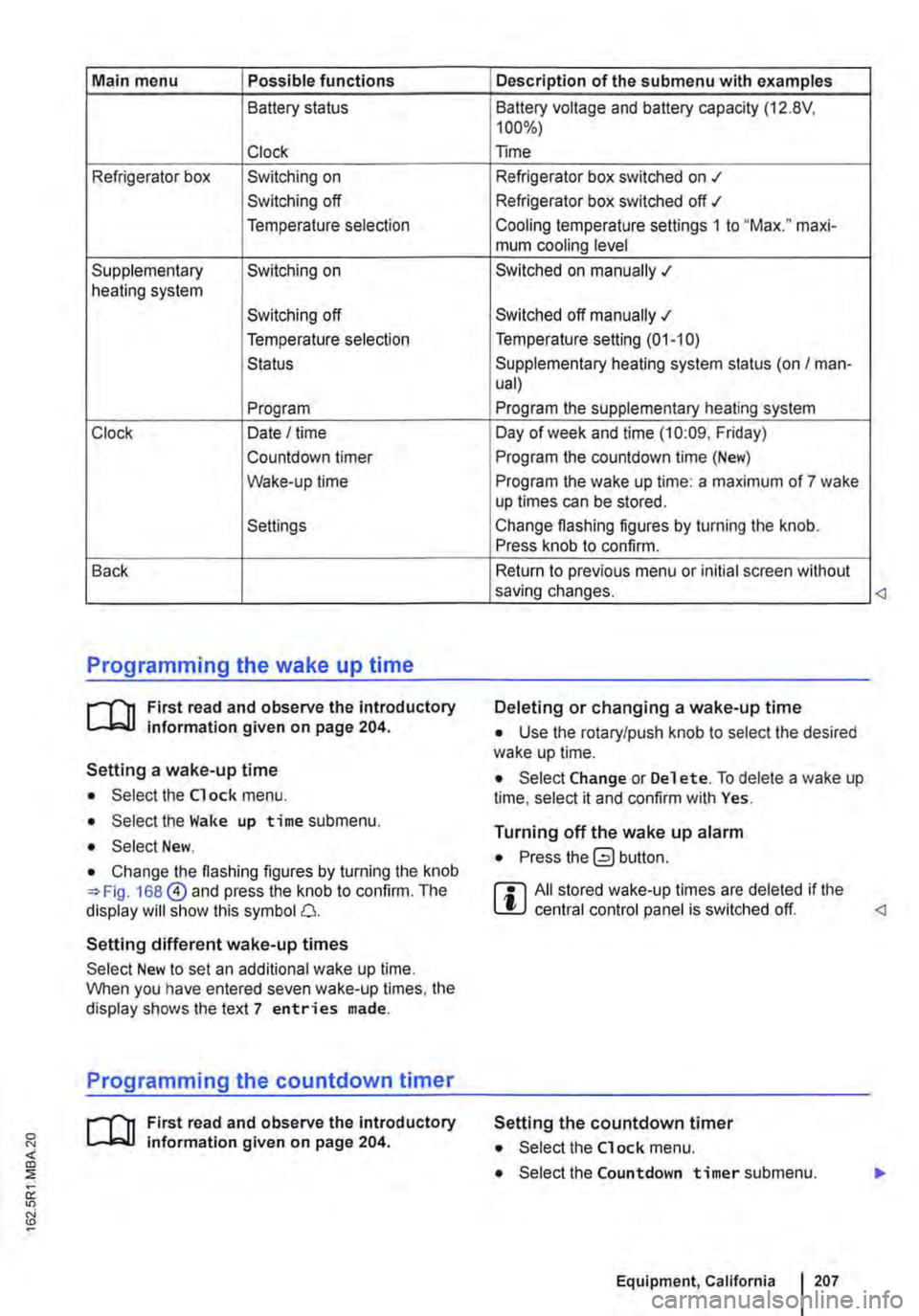
Main menu Possible functions
Battery status
Clock
Refrigerator box Switching on
Switching off
Temperature selection
Supplementary Switching on heating system
Switching off
Temperature selection
Status
Program
Clock Date I time
Countdown timer
Wake-up time
Settings
Back
Programming the wake up time
r--f"'n First read and observe the introductory L-lo::.U information given on page 204.
Setting a wake-up time
• Select the Clock menu.
• Select the Wake up time submenu.
• Select New.
• Change the flashing figures by turning the knob 168@ and press the knob to confirm. The display will show this symbol 0.
Setting different wake-up times
Select New to set an additional wake up time. When you have entered seven wake-up times, the display shows the text 7 entries made.
Programming the countdown timer
r--f"'n First read and observe the introductory L-lo::.U information given on page 204.
Description of the submenu with examples
Battery voltage and battery capacity (12.8V, 100%)
Time
Refrigerator box switched on .t
Refrigerator box switched off ./
Cooling temperature settings 1 to "Max." maxi-mum cooling level
Switched on manually .;
Switched off manually .;
Temperature setting (01-10)
Supplementary heating system status (on I man-ual)
Program the supplementary heating system
Day of week and time (10:09. Friday)
Program the countdown time (New)
Program the wake up time: a maximum of 7 wake up times can be stored.
Change flashing figures by turning the knob. Press knob to confirm.
Return to previous menu or initial screen without saving changes.
Deleting or changing a wake-up time
• Use the rotary/push knob to select the desired wake up time.
• Select Change or Del et e. To delete a wake up time, select it and confirm with Yes.
Turning off the wake up alarm
• Press button.
r::l All stored wake-up times are deleted if the L!J central control panel is switched off.
Setting the countdown timer
• Select the Clock menu.
• Select the Countdown timer submenu.
Equipment, California I 207
Page 208 of 486
• Select New.
• Change the flashing figures by turning the knob 168 @) and press the knob to confirm.
Deleting the countdown timer
• Use the rotary/push knob to select the count-down timer.
• Select Delete and confirm by selecting Yes.
Changing the countdown timer setting
• Select New.
• Change the flashing figures by turning the knob 168@) and press the knob to confirm. The old countdown timer setting is automatically over-written.
Interior lights, California
CClJ Introduction
This chapter contains information on the following subjects:
Interior lights in the living area . . . . • . • . . . . . . 209
Interior lights in the pop-up roof . . . . . . . . . . . 210
Additional information:
• Electrical sockets 163
• Battery 350
208 Before the journey
Turning off the countdown timer
• Press the (2) button.
W The stored countdown timer setting is deleted L!J if the central control panel is switched off. <
• Cigarette lighter 163
• Accessories, modifications, repairs and renewal of parts 394
• Fuses 429
• Consumer information 404
• Rectifying faults on the camping equipment 254
Page 251 of 486
Supplementary heater, California
o:JJ Introduction
This chapter contains information on the following subjects:
Programming the supplementary heater. . . . . 251
The supplementary heating system is supplied with fuel from the vehicle fuel tank and can be used when the vehicle is in motion or stationary.
Additional information:
• Central control panel 204
• Supplementary heaters 322
• Rectifying faults on the camping equipment 254
A WARNING
The fumes from the supplementary heating system contain carbon monoxide, which is an odourless and colourless poisonous gas. Carbon monoxide can cause people to lose consciousness. lt can also cause death.
A WARNING (Continued)
• Never start or run the supplementary heat-ing system in unventilated or closed rooms.
• Never programme the auxiliary heater so that it is switched on and run in unventilated or enclosed spaces.
A WARNING
Parts of the exhaust system of the supple-mentary heating system become very hot. This can cause fires.
• Park the vehicle so that no part of the ex-haust system can come into contact with any inflammable material underneath the vehicle, e.g. dry grass.
CD
Do not place any food, medicine or any other heat-sensitive items In front of the vents. Heat-sensitive food, medicine and other items could be either damaged or rendered useless.
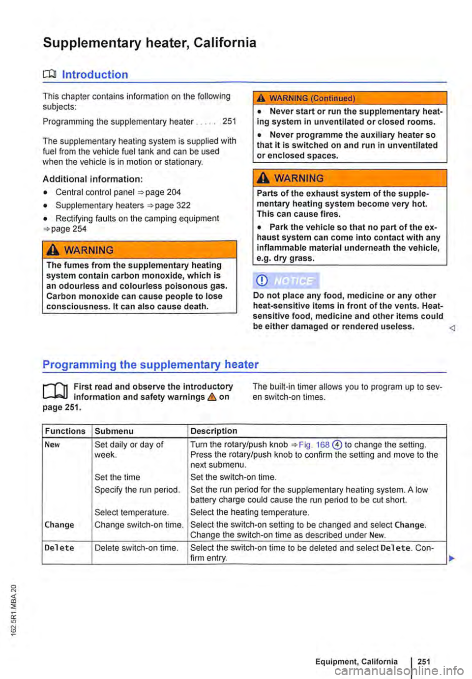
,.....-('n First read and observe the introductory L-bl.l information and safety warnings & on page 251.
The built-in timer allows you to program up to sev-en switch-on times.
Functions Submenu Description
New Set daily or day of Turn the rotary/push knob 168@ to change the setting. week. Press the rotary/push knob to confirm the setting and move to the next submenu.
Set the time Set the switch-on time.
Specify the run period. Set the run period for the supplementary heating system. A low battery charge could cause the run period to be cut short.
Select temperature. Select the heating temperature.
Change Change switch-on time. Select the switch-on setting to be changed and select Change. Change the switch-on time as described under New.
Delete Delete switch-on time. Select the switch-on time to be deleted and select Delete. Con-firm entry.
Equipment, California I 251
Page 264 of 486
Dual clutch gearbox DSG®
r-('n First read and observe the Introductory L-.lo:on Information and safety warnings & on page 260.
Description
The DSG® dual clutch gearbox is a gearbox which uses dual-clutch technology to change gear automatically. it uses a dual clutch and two independent gearboxes to enable very fast gear changes with no loss of torque. The DSG® dual clutch gearbox thus combines the performance and economy of a manual gearbox with the com-fort and convenience of a conventional automatic transmission.
How the system works
Engine power is transferred to the drive shafts via the gearbox. In order to change gears, the power transmission between the engine and the gearbox has to be interrupted. This is what the clutch is for.
With the DSG® dual clutch system with its two complementary gearboxes, one gearbox is always connected under load to the engine. When one gear is engaged, another gear is always preselec-
led in the other gearbox. The clutch on the non-driven gear is closed and the other is opened at the same time. This is what makes very fast gear changes possible.
The DSG® dual clutch gearbox is designed to be more efficient than an automatic gearbox. In an au-tomatic gearbox, the torque converter is constantly in use, whereas in the DSG® dual clutch system the idle clutch can be opened, thus saving fuel. With its efficiency, low weight and intelligent control system, the DSG® dual clutch system usually ena-bles fuel consumption equal to or lower than a manual gearbox.
like the manual gearbox, the clutch in the DSG dual clutch system is subject to wear. Regular maintenance is necessary, varying accord-ing to what type of DSG® dual clutch system is in-stalled. For more information see the service schedule. In the DSG® dual clutch system, if one gearbox malfunctions it is deactivated and the oth-er gearbox functions alone *page 267. If this happens, have the system checked as soon as possible by a qualified workshop.
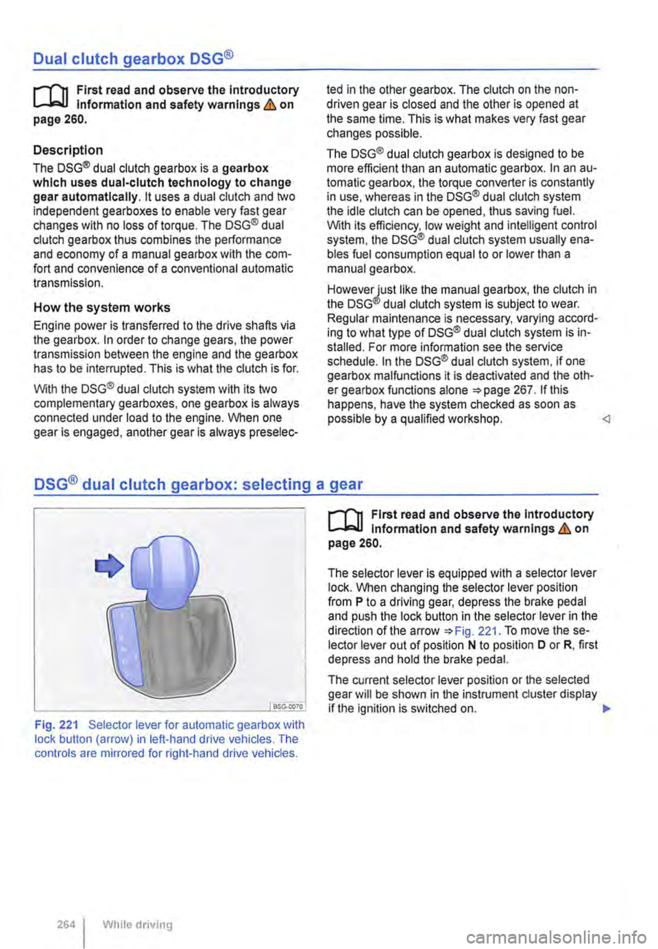
Fig. 221 Selector lever for automatic gearbox with lock button (arrow) in left-hand drive vehicles. The controls are mirrored for right-hand drive vehicles.
264 I While driving
r-('n First read and observe the Introductory L-.lo:on Information and safety warnings & on page 260.
The selector lever is equipped with a selector lever lock. When changing the selector lever position from P to a driving gear, depress the brake pedal and push the lock button in the selector lever in the direction of the arrow *Fig. 221. To move the se-lector lever out of position N to position D or R, first depress and hold the brake pedal.
The current selector lever position or the selected gear will be shown in the instrument duster display if the ignition is switched on. .,..
Page 265 of 486
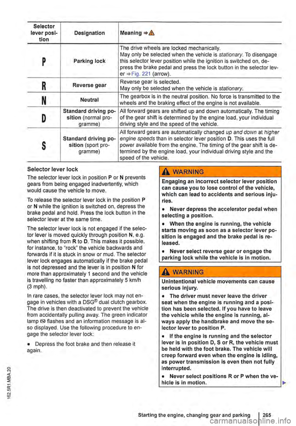
Selector lever posl-Designation Meaning=>& tlon
The drive wheels are locked mechanically.
p May only be selected when the vehicle is stationary. To disengage Parking lock this selector lever position while the ignition is switched on, de-press the brake pedal and press the lock button in the selector lev-er=> Fig. 221 (arrow).
R Reverse gear Reverse gear is selected. May only be selected when the vehicle is stationary.
N Neutral The gearbox is in the neutral position. No force is transmitted to the wheels and the braking effect of the engine is not available.
D
Standard driving po-All forward gears are shifted up and down automatically. The timing sition (normal pro-of the gear shift is determined by the engine load, your individual gramme) driving style and the speed of the vehicle.
All forward gears are automatically changed up and down at higher
s
Standard driving po-engine speeds than in selector lever position D. This uses the full sltlon (sport pro-power available from the engine. The timing of the gear shift is de-gramme) !ermined by the engine load, your individual driving style and the speed of the vehicle.
Selector lever lock
The selector lever lock in position P or N prevents gears from being engaged inadvertently, which would cause the vehicle to move.
To release the selector lever lock in the position P or N while the ignition is switched on, depress the brake pedal and hold. Press the lock button in the selector lever at the same time.
The selector lever lock is not engaged if the selec-tor lever Is moved quickly through position N, e.g. when shifting from R to D. This makes it possible, for Instance, to "rock" the vehicle backwards and forwards if it is stuck in snow or mud. The selector lever lock engages automatically if the brake pedal is not depressed and the lever is in position N for more than approximately 1 second and the vehicle is travelling no faster than approximately 5 km/h (3 mph).
In rare cases, the selector lever lock may not en-gage in vehicles with a DSG® dual clutch gearbox. The drive is then deactivated to prevent the vehicle from accidentally pulling away. The green indicator lamp IS> flashes and an information message is al-so displayed. Use the following procedure to en-gage the selector lever lock:
• Depress the foot brake and then release it again.
,A WARNING
Engaging an incorrect selector lever position can cause you to lose control of the vehicle, which can lead to accidents and serious inju-ries.
• Never depress the accelerator pedal when selecting a position.
• When the engine is running, the vehicle starts moving as soon as a selector lever po-sition is engaged and the brake pedal Is re-leased.
• Never select reverse gear or engage the parking lock while the vehicle Is In motion.
A WARNING
Unintentional vehicle movements can cause serious Injury.
• The driver must never leave the driver seat when the engine is running and a posi-tion has been selected. If you have to leave the vehicle while the engine Is running, al-ways apply the handbrake and move the se-lector lever to position P.
• If the engine is running and the selector lever Is in position D, S or R, the vehicle must be held with the foot brake. The vehicle will creep forward even when the engine Is idling, as power transmission Is even then not fully Interrupted.
• Never select positions R or P when the ve-hicle is In motion.
Starting the engine, changing gear and parking 265
Page 266 of 486
A WARNING (Continued)
• Never leave the vehicle in driving mode N. The vehicle will roll downhill irrespective of whether or not the engine is running.
CD
If the handbrake is not applied when the vehi-cle Is stationary and the brake pedal is released when then selector lever Is In position P, the vehicle may move a few centimetres forwards or backwards.
Changing gear with Tiptronic
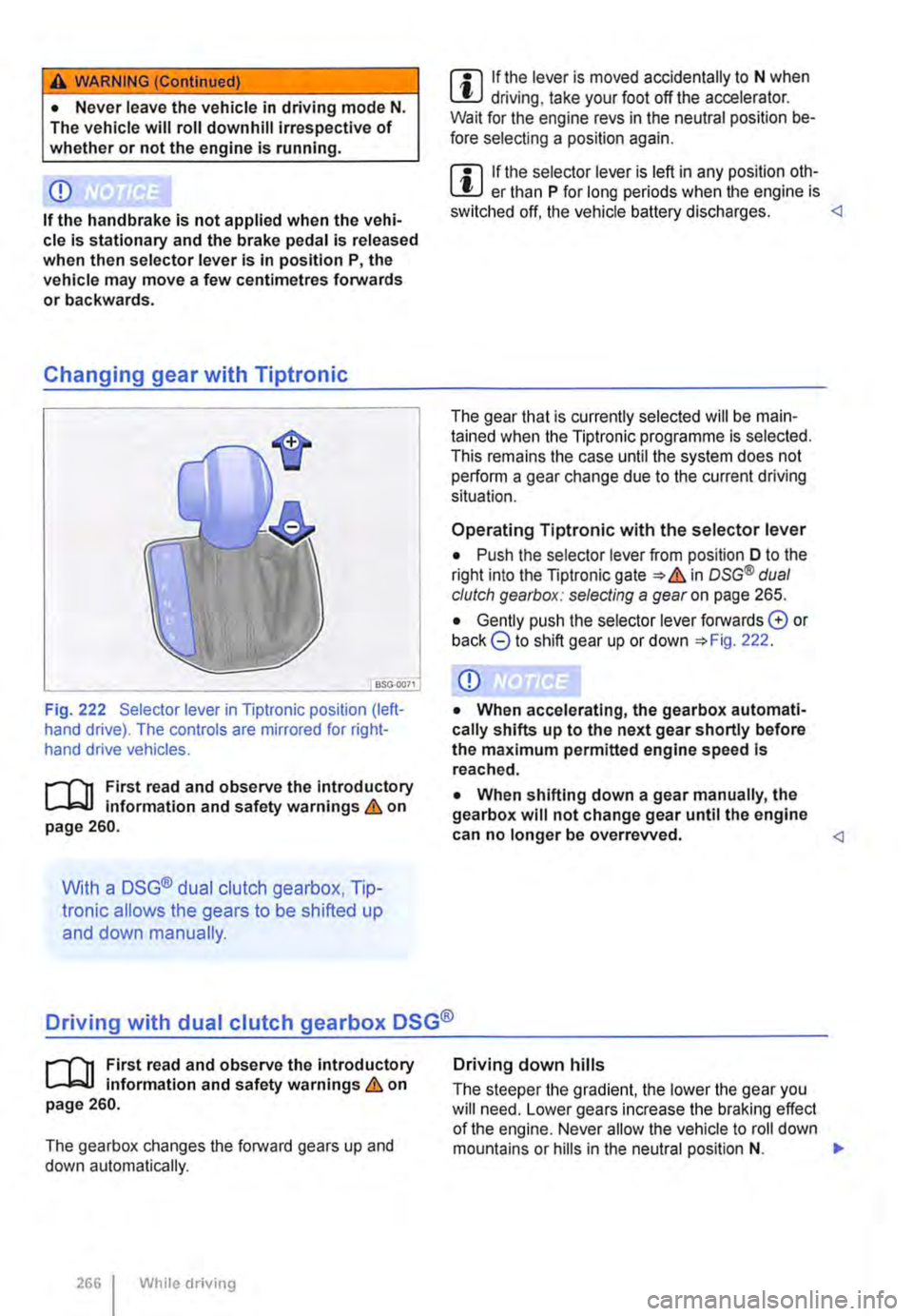
Fig. 222 Selector lever in Tiptronic position (left-hand drive). The controls are mirrored for right-hand drive vehicles.
r--T'n First read and observe the introductory L-lc:J.I Information and safety warnings & on page 260.
With a DSG® dual clutch gearbox, Tip-
Ironic allows the gears to be shifted up
and down manually.
m If the lever is moved accidentally to N when l!J driving, take your foot off the accelerator. Wait for the engine revs in the neutral position be-fore selecting a position again.
m If the selector lever is left in any position oth-L!J er than P for long periods when the engine is switched off, the vehicle battery discharges.
Operating Tiptronic with the selector lever
• Push the selector lever from position D to the right into the Tiptronic gate & in osG® dual clutch gearbox: selecting a gear on page 265.
• Gently push the selector lever forwards G or back 8 to shift gear up or down 222.
CD
• When accelerating, the gearbox automati-cally shifts up to the next gear shortly before the maximum permitted engine speed Is reached.
• When shifting down a gear manually, the gearbox will not change gear until the engine can no longer be overrevved.
r--T'n First read and observe the introductory L-lc:J.I information and safety warnings & on page 260.
The gearbox changes the forward gears up and down automatically.
2661 While driving
Driving down hills
The steeper the gradient, the lower the gear you will need. Lower gears increase the braking effect of the engine. Never allow the vehicle to roll down mountains or hills in the neutral position N. ,..
Page 268 of 486
In all cases the automatic gearbox should be checked by a qualified workshop Immediately.
Overheating of the DSG® dual clutch gearbox
The dual clutch gearbox can overheat when the vehicle pulls off regularly, travels at a crawl for long periods, or in stop and go traffic. Gearbox over-heating is indicated by the warning lamp (j) and in some cases by a text message in the instrument cluster display. A signal tone may also be given. Stop the vehicle and allow the gearbox to cool down
The vehicle will not move forwards or backwards even though a gear has been selected
If the vehicle will not move in the required direc-tion, the system may have selected the position in-correctly. Depress the brake pedal and reselect the position.
Gear-change indicator
r--f"'n First read and observe the Introductory L-lo:.l.l information and safety warnings & on page 260.
Depending on the vehicle equipment level, the in-strument cluster may indicate the gear which you should select in order to reduce fuel consumption while the vehicle is in motion.
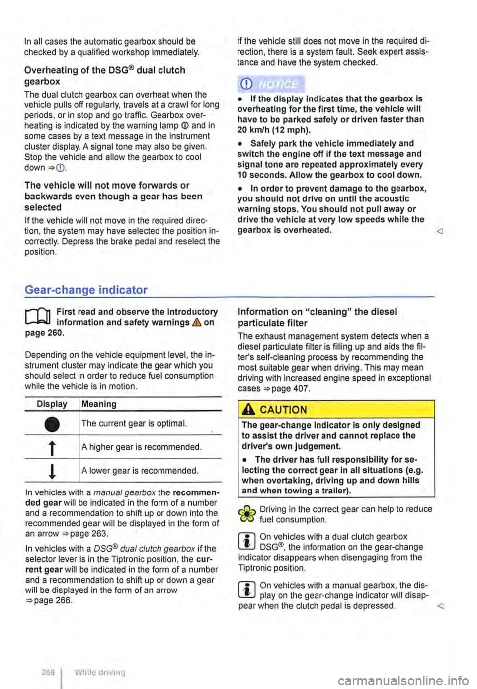
Display Meaning
• The current gear is optimal.
f A higher gear is recommended.
! A lower gear is recommended.
In vehicles with a manual gearbox the recommen-ded gear will be indicated in the form of a number and a recommendation to shift up or down into the recommended gear will be displayed in the form of an arrow 263.
In vehicles with a OSG® dual clutch gearbox if the selector lever is in the Tiptronic position, the cur-rent gear will be indicated in the form of a number and a recommendation to shift up or down a gear will be displayed in the form of an arrow 266.
268 While driving
If the vehicle still does not move in the required di-rection, there is a system fault. Seek expert assis-tance and have the system checked.
CD
• If the display Indicates that the gearbox Is overheating for the first time, the vehicle will have to be parked safely or driven faster than 20 kmlh (12 mph).
• Safely park the vehicle immediately and switch the engine off if the text message and signal tone are repeated approximately every 10 seconds. Allow the gearbox to cool down.
• In order to prevent damage to the gearbox, you should not drive on until the acoustic warning stops. You should not pull away or drive the vehicle at very low speeds while the gearbox is overheated.
The exhaust management system detects when a diesel particulate filter is filling up and aids the fil-ter's self-cleaning process by recommending the most suitable gear when driving. This may mean driving with Increased engine speed in exceptional cases 407.
A CAUTION
The gear-change Indicator Is only designed to assist the driver and cannot replace the driver's own judgement.
• The driver has full responsibility for se-lecting the correct gear In all situations (e.g. when overtaking, driving up and down hills and when towing a trailer).
Driving in the correct gear can help to reduce fuel consumption.
m On vehicles with a dual clutch gearbox W DSG®, the information on the gear-change indicator disappears when disengaging from the Tiptronic position.
m On vehicles with a manual gearbox, the dis-W play on the gear-change indicator will disap-pear when the clutch pedal is depressed.
Page 273 of 486
heavy load on the brakes should be avoided. For example, when driving too close to the vehicle ahead.
The rate of wear of the brake pads depends to a great extent on the conditions under which the ve-hicle is operated and the way in which the vehicle is driven. With regular urban trips, short journeys and a sporty driving style, the brake pads must be checked by a qualified workshop more regularly than stated in the service schedule.
When driving with wet brakes, for example after driving through water, after heavy rainfall or after washing the vehicle, the braking effect may be de-layed as the brake discs will be wet, or possibly ic-ed up (in winter). The brakes must be "dried" as quickly as possible by careful braking at higher speed. Ensure that no vehicle behind you or no other road user is put at risk as a result of this ac-
Any salt layer accumulating on the discs and pads will delay the braking effect and increase the braking distance. If the brakes on the vehicle have not been applied for a long time on roads that have been gritted with salt, the layer of salt must be re-duced through careful braking &.
Corrosion on the brake discs and dirt in the brake pads are facilitated through long periods of inactivi-ty, low mileage and low load levels. With inactivity or low use levels for the brake pads as well as cor-rosion, Volkswagen Commercial Vehicles recom-mends that the brake discs and brake pads be cleaned by braking strongly several times from high speed. Ensure that no vehicle behind you or no other road user is put at risk as a result of this
Fault in the brake system
A brake circuit may have failed if you have to re-duce speed and the vehicle does not brake as nor-mal (sudden increase in braking distance). This will be indicated by the warning lamp m and in some cases a text message. Go to the nearest qualified workshop immediately to have the fault corrected. Drive at low speed when doing this and anticipate much longer braking distances and an increase in the pressure required on the pedal.
Brake servo
The brake serve will only function when the engine is running and reinforces the pressure applied by the driver on the brake pedal.
If the brake serve is not functioning or the vehicle is being towed, the brake pedal will have to be de-pressed more forcefully as the braking distance will be increased due to the lack of assistance for the brake system &.
A WARNING
New brake pads will not have the optimal braking effect when first fitted.
• New brake pads cannot generate the full braking effect during the first 300 km and must first be run In. A reduced braking effect can be Increased by applying more pressure to the brake pedal.
• You must drive particularly carefully when driving with new brake pads In order to re-duce the risk of accidents, serious Injuries and loss of control of the vehicle.
• Never drive too close to other vehicles when running in new brake pads, and never create a driving situation that will place a heavy load on the brakes.
A WARNING
Overheated brakes reduce the braking effect and considerably Increase the braking dis-tance.
• When driving downhill the brakes are placed under particular strain and become hot very quickly.
• Before driving down a long, steep gradi-ent, reduce speed and change to a lower gear or move the selector lever to a lower position. This will make use of the engine braking ef-fect and relieve the load on the brakes.
• Non-standard or damaged front spoilers could restrict the airflow to the brakes and cause them to overheat.
A WARNING
Wet brakes or brakes coated with ice or road salt react more slowly and require longer braking distances.
• Carefully apply the brakes to test them.
• Always dry brakes and clean off any coat-Ing of Ice and salt with a few cautious appli-cations of the brake when visibility, weather, road and traffic conditions permit.
A WARNING
Driving without the brake servo can consider-ably Increase the braking distance and thus cause accidents and serious Injuries.
• Never allow the vehicle to roll if the engine Is switched off.
Starting the engine, changing gear and parking 273
Page 274 of 486

A WARNING (Continued)
• If the brake servo does not function or the vehicle is being towed, the brake pedal will have to be depressed more forcefully as the braking distance will be Increased due to the lack of assistance for the brake system.
CD
• Never let the brakes "rub" by applying light pressure to the brake when it is not necessary to brake. Continual pressure on the brake pedal will overheat the brakes. This can considerably reduce the brake effect, increase the braking distance and, In certain circumstances, cause the brake system to fail completely.
Brake support systems
r-f'n First read and observe the Introductory l..-Wl information and safety warnings&. on page 269.
The brake support systems ESC, ABS, BAS, TCS and EDL only function when the engine is running. They make a considerable contribution to active driving safety.
Electronic stability control (ESC)
The ESC helps to reduce the risk of skidding and to improve driving stability by braking individual wheels in certain driving situations. The ESC de-tects critical driving situations such as oversteer, understeer and wheelspin. The system helps to stabilise the vehicle through targeted application of the brakes or by reducing engine torque.
ESC has its limitations. lt is important to realise that ESC cannot overcome the laws of physics. ESC will not be able to assist in every situation faced by a driver. For example, ESC will not be able to assist every time that there is a sudden change in the road surface quality. If a section of dry road is suddenly covered with water, mud or snow, ESC will not be able to assist in the same manner as on a dry road. If the vehicle aquaplanes (drives on a layer of water rather than on the road surface), ESC will not be able to assist in steering the vehicle as the contact to the road surface has been interrupted and it is therefore no longer pos-sible to steer or brake the vehicle. When driving at speed through bends, particularly on stretches of road with many bends, the ESC will not always be able to process complicated driving situations as
2741 While dnvang
m If the front brake pads are tested, the rear L!..J brake pads should be tested at the same time. Regularly check the thickness of the brake pads through the openings in the rims or from the underside of the vehicle. If necessary, remove the wheels to carry out a comprehensive check. Volks-wagen Commercial Vehicles recommends using a Volkswagen Commercial Vehicles dealership for this purpose.
Always adapt your speed and driving style to suit visibility, weather, road and traffic conditions. ESC cannot defy the laws of motion, improve the availa-ble power output, or keep the vehicle on the road if insufficient care and attention on the part of the driver causes the vehicle to leave the road. In-stead, the ESC improves the chances of keeping the vehicle under control and, in extreme on-road driving situations, exploits the driver's steering in-put to keep the vehicle travelling in the desired di-rection. If the vehicle is driving at a speed that leads it to leave the road before the ESC can pro-vide any kind of support, the ESC will be unable to provide any assistance.
The ASS, BAS, TCS and EDL systems are integra-ted into the ESC. The ESC is always on. If the trac-tion achieved in certain situations is not sufficient, TCS can be switched off by pressing the ASR (TCS) button =>Fig. 224. Always ensure that ASR (TCS) is switched back on again once traction is sufficient.
Automatic Post-Collision Braking System
In the event of an accident, the Automatic Post-Collision Braking System can help the driver to re-duce the risk of skidding, and the danger of secon-dary collisions, through automatic braking.
Page 277 of 486
Brake fluid
B7E.02AO
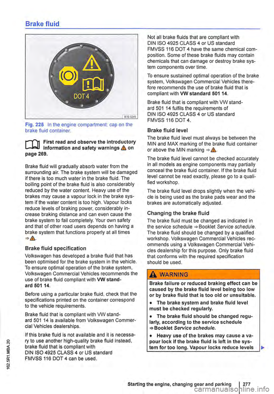
Fig. 225 In the engine compartment: cap on the brake fluid container.
r-111 First read and observe the Introductory l-Jr:,U Information and safety warnings&. on page 269.
Brake fluid will gradually absorb water from the surrounding air. The brake system will be damaged if there is too much water in the brake fluid. The boiling point of the brake fluid is also considerably reduced by the water content. Heavy use of the brakes may cause a vapour lock in the brake sys-tem if the water content is too high. Vapour locks reduce levels of braking power, considerably in-crease braking distance and can even cause the brake system to fail completely. Your own safety and that of other road users depends on having a brake system that functions properly at all times
Brake fluid specification
Volkswagen has developed a brake fluid that has been optimised for the brake system in the vehicle. To ensure optimal operation of the brake system, Volkswagen Commercial Vehicles recommends the use of brake fluid compliant with VW stand-ard 501 14.
Before using a particular brake fluid, check that the specifications printed on the container correspond to the vehicle requirements.
Brake fluid that is compliant with VW stand-ard 501 14 is available from Volkswagen Commer-cial Vehicles dealerships.
If this brake fluid is not available and it is necessa-ry to use another high-quality brake fluid instead, brake fluid that is compliant with DIN ISO 4925 CLASS 4 or US standard FMVSS 116 DOT 4 can be used.
Not all brake fluids that are compliant with DIN ISO 4925 CLASS 4 or US standard FMVSS 116 DOT 4 have the same chemical com-position. Some of these brake fluids may contain chemicals that can damage or destroy brake sys-tem components over time.
To ensure sustained optimal operation of the brake system, Volkswagen Commercial Vehicles there-fore recommends the use of brake fluid that is compliant with VW standard 501 14.
Brake fluid that is compliant with VW stand-ard 501 14 fulfils the requirements of DIN ISO 4925 CLASS 4 or US standard FMVSS 116 DOT 4.
Brake fluid level
The brake fluid level must always be between the MIN and MAX marking of the brake fluid container or above the MIN marking &.
The brake fluid level cannot be checked accurately in all models as engine components may partially conceal the brake fluid container. If the brake fluid level cannot be read exactly, please go to a quali-fied workshop.
The brake fluid level drops slightly when the vehi-cle is being used as the brake pads wear and the brakes are automatically adjusted.
Changing the brake fluid
The brake fluid must be changed as indicated in the service schedule Service schedule. The brake fluid should be changed by a qualified workshop. Volkswagen Commercial Vehicles rec-ommends using a Volkswagen Commercial Vehi-cles dealership for this purpose. Only brake fluid that confonns with the required specification should be used.
A WARNING
Brake failure or reduced braking effect can be caused by the brake fluid level being too low or by brake fluid that Is too old or unsuitable.
• The brake system and brake fluid level must be checked regularly.
• The brake fluid should be changed regu-larly, according to the service schedule Service schedule.
• Heavy use of the brakes may cause a va-pour lock If the brake fluid Is left In the sys-tem for too long. Vapour locks reduce levels
Starting the engine, changing gear and parking I 277